EP0888490B1 - Fraise servant a effectuer des operations de fraisage dans un puits de forage - Google Patents
Fraise servant a effectuer des operations de fraisage dans un puits de forage Download PDFInfo
- Publication number
- EP0888490B1 EP0888490B1 EP96934987A EP96934987A EP0888490B1 EP 0888490 B1 EP0888490 B1 EP 0888490B1 EP 96934987 A EP96934987 A EP 96934987A EP 96934987 A EP96934987 A EP 96934987A EP 0888490 B1 EP0888490 B1 EP 0888490B1
- Authority
- EP
- European Patent Office
- Prior art keywords
- mill
- fluid
- whipstock
- flow control
- milling
- Prior art date
- Legal status (The legal status is an assumption and is not a legal conclusion. Google has not performed a legal analysis and makes no representation as to the accuracy of the status listed.)
- Expired - Lifetime
Links
- 238000003801 milling Methods 0.000 title claims description 30
- 239000012530 fluid Substances 0.000 claims description 77
- 238000000034 method Methods 0.000 claims description 5
- 238000003780 insertion Methods 0.000 claims description 3
- 230000037431 insertion Effects 0.000 claims description 3
- 238000002955 isolation Methods 0.000 claims description 3
- 239000007787 solid Substances 0.000 description 12
- 238000005553 drilling Methods 0.000 description 7
- 239000004568 cement Substances 0.000 description 5
- 241000219109 Citrullus Species 0.000 description 4
- 235000012828 Citrullus lanatus var citroides Nutrition 0.000 description 4
- 238000010008 shearing Methods 0.000 description 4
- LYCAIKOWRPUZTN-UHFFFAOYSA-N Ethylene glycol Chemical compound OCCO LYCAIKOWRPUZTN-UHFFFAOYSA-N 0.000 description 3
- 239000000463 material Substances 0.000 description 2
- 229910001104 4140 steel Inorganic materials 0.000 description 1
- 229910000851 Alloy steel Inorganic materials 0.000 description 1
- 229910001369 Brass Inorganic materials 0.000 description 1
- 229910001209 Low-carbon steel Inorganic materials 0.000 description 1
- 229910000831 Steel Inorganic materials 0.000 description 1
- XAGFODPZIPBFFR-UHFFFAOYSA-N aluminium Chemical compound [Al] XAGFODPZIPBFFR-UHFFFAOYSA-N 0.000 description 1
- 229910052782 aluminium Inorganic materials 0.000 description 1
- 230000004888 barrier function Effects 0.000 description 1
- 239000010951 brass Substances 0.000 description 1
- -1 but not limited to Substances 0.000 description 1
- 238000005520 cutting process Methods 0.000 description 1
- 238000006073 displacement reaction Methods 0.000 description 1
- 239000000945 filler Substances 0.000 description 1
- 239000011159 matrix material Substances 0.000 description 1
- 239000010959 steel Substances 0.000 description 1
- XLYOFNOQVPJJNP-UHFFFAOYSA-N water Substances O XLYOFNOQVPJJNP-UHFFFAOYSA-N 0.000 description 1
- 238000003466 welding Methods 0.000 description 1
Images




Classifications
-
- E—FIXED CONSTRUCTIONS
- E21—EARTH OR ROCK DRILLING; MINING
- E21B—EARTH OR ROCK DRILLING; OBTAINING OIL, GAS, WATER, SOLUBLE OR MELTABLE MATERIALS OR A SLURRY OF MINERALS FROM WELLS
- E21B23/00—Apparatus for displacing, setting, locking, releasing or removing tools, packers or the like in boreholes or wells
- E21B23/06—Apparatus for displacing, setting, locking, releasing or removing tools, packers or the like in boreholes or wells for setting packers
-
- E—FIXED CONSTRUCTIONS
- E21—EARTH OR ROCK DRILLING; MINING
- E21B—EARTH OR ROCK DRILLING; OBTAINING OIL, GAS, WATER, SOLUBLE OR MELTABLE MATERIALS OR A SLURRY OF MINERALS FROM WELLS
- E21B10/00—Drill bits
- E21B10/46—Drill bits characterised by wear resisting parts, e.g. diamond inserts
- E21B10/50—Drill bits characterised by wear resisting parts, e.g. diamond inserts the bit being of roller type
-
- E—FIXED CONSTRUCTIONS
- E21—EARTH OR ROCK DRILLING; MINING
- E21B—EARTH OR ROCK DRILLING; OBTAINING OIL, GAS, WATER, SOLUBLE OR MELTABLE MATERIALS OR A SLURRY OF MINERALS FROM WELLS
- E21B23/00—Apparatus for displacing, setting, locking, releasing or removing tools, packers or the like in boreholes or wells
- E21B23/04—Apparatus for displacing, setting, locking, releasing or removing tools, packers or the like in boreholes or wells operated by fluid means, e.g. actuated by explosion
- E21B23/0411—Apparatus for displacing, setting, locking, releasing or removing tools, packers or the like in boreholes or wells operated by fluid means, e.g. actuated by explosion specially adapted for anchoring tools or the like to the borehole wall or to well tube
-
- E—FIXED CONSTRUCTIONS
- E21—EARTH OR ROCK DRILLING; MINING
- E21B—EARTH OR ROCK DRILLING; OBTAINING OIL, GAS, WATER, SOLUBLE OR MELTABLE MATERIALS OR A SLURRY OF MINERALS FROM WELLS
- E21B23/00—Apparatus for displacing, setting, locking, releasing or removing tools, packers or the like in boreholes or wells
- E21B23/04—Apparatus for displacing, setting, locking, releasing or removing tools, packers or the like in boreholes or wells operated by fluid means, e.g. actuated by explosion
- E21B23/042—Apparatus for displacing, setting, locking, releasing or removing tools, packers or the like in boreholes or wells operated by fluid means, e.g. actuated by explosion using a single piston or multiple mechanically interconnected pistons
-
- E—FIXED CONSTRUCTIONS
- E21—EARTH OR ROCK DRILLING; MINING
- E21B—EARTH OR ROCK DRILLING; OBTAINING OIL, GAS, WATER, SOLUBLE OR MELTABLE MATERIALS OR A SLURRY OF MINERALS FROM WELLS
- E21B29/00—Cutting or destroying pipes, packers, plugs or wire lines, located in boreholes or wells, e.g. cutting of damaged pipes, of windows; Deforming of pipes in boreholes or wells; Reconditioning of well casings while in the ground
- E21B29/06—Cutting windows, e.g. directional window cutters for whipstock operations
-
- E—FIXED CONSTRUCTIONS
- E21—EARTH OR ROCK DRILLING; MINING
- E21B—EARTH OR ROCK DRILLING; OBTAINING OIL, GAS, WATER, SOLUBLE OR MELTABLE MATERIALS OR A SLURRY OF MINERALS FROM WELLS
- E21B34/00—Valve arrangements for boreholes or wells
- E21B34/06—Valve arrangements for boreholes or wells in wells
- E21B34/10—Valve arrangements for boreholes or wells in wells operated by control fluid supplied from outside the borehole
-
- E—FIXED CONSTRUCTIONS
- E21—EARTH OR ROCK DRILLING; MINING
- E21B—EARTH OR ROCK DRILLING; OBTAINING OIL, GAS, WATER, SOLUBLE OR MELTABLE MATERIALS OR A SLURRY OF MINERALS FROM WELLS
- E21B34/00—Valve arrangements for boreholes or wells
- E21B34/06—Valve arrangements for boreholes or wells in wells
- E21B34/10—Valve arrangements for boreholes or wells in wells operated by control fluid supplied from outside the borehole
- E21B34/101—Valve arrangements for boreholes or wells in wells operated by control fluid supplied from outside the borehole with means for equalizing fluid pressure above and below the valve
-
- E—FIXED CONSTRUCTIONS
- E21—EARTH OR ROCK DRILLING; MINING
- E21B—EARTH OR ROCK DRILLING; OBTAINING OIL, GAS, WATER, SOLUBLE OR MELTABLE MATERIALS OR A SLURRY OF MINERALS FROM WELLS
- E21B7/00—Special methods or apparatus for drilling
- E21B7/04—Directional drilling
- E21B7/06—Deflecting the direction of boreholes
- E21B7/061—Deflecting the direction of boreholes the tool shaft advancing relative to a guide, e.g. a curved tube or a whipstock
Definitions
- This invention relates to a mill for wellbore milling operations.
- an anchor is first lowered down a casing and set at a desired position.
- a whipstock is then lowered down the casing and seated on the anchor.
- a starting mill is then lowered down the casing and is deflected radially against the wall of the casing by the whipstock whilst being simultaneously rotated. This cuts a window in the casing.
- the starting mill is then withdrawn and a window mill or a water melon mill lowered down the casing and rotated to enlarge the initial window and smooth the edges thereof.
- GB-A-2 227 038 and US-A-5392862 disclose a mill for wellbore milling operations, said mill comprising a body with a bore therethrough for fluid flow through said mill, at least one milling surface on the body, and flow control apparatus within the body for selectively controlling fluid flow through the mill.
- US-A-5443129 discloses an apparatus for setting a hydraulically activatable mechanism in a borehole and drilling an additional hole in a single trip by having the hydraulically actuatable mechanism connected to the drillstring.
- US-A-4324299 discloses a turbodrill with two rotary seals in fluid communication providing pressure-balanced bearing seals.
- a mill for wellbore milling operations provided with means for actuating an item below the mill, the mill comprising a body with a bore therethrough for fluid flow through said mill, at least one milling surface on the body, and flow control apparatus within the body for selectively controlling fluid flow through the mill, characterised in that said flow control apparatus includes a first flow control device activatable by fluid at a first fluid pressure for permitting fluid at the first pressure to actuate the item below the mill.
- Another problem lies in determining whether a whipstock is properly seated and/or ensuring that he concave of the whipstock is properly disposed with respect to the casing. This is achieved by lowering the travelling block on the surface and noting whether there is an appropriate decrease in load.
- the problem with this operation is that the whipstock is typically attached (directly or indirectly) to the tool string by a shear pin which may inadvertently shear when the travelling block is lowered.
- a mill for wellbore milling operations comprising a body with at least one milling surface thereon, and force isolation apparatus on the body for isolating a shearable member releasably connecting the mill to another member from a downward force on the mill.
- the present invention also provides a method for installing a milling system in a wellbore lined with casing, the milling system having a mill releasably connected to a whipstock and an anchor connected to the whipstock, the mill comprising a body with a bore therethrough for fluid flow through the mill, at least one milling surface on the body, and flow control apparatus within the body for selectively controlling fluid flow through the mill, the flow control apparatus including a first flow control device activatable by fluid at a first fluid pressure for permitting fluid at the first pressure to flow from the mill for actuating the anchor, the method comprising inserting the milling system into the casing, and flowing fluid at the first fluid pressure through the mill and through the first flow control device to the anchor to set the anchor in the casing.
- said mill further comprises an amount of fluid confined within the bore prior to insertion of the mill into the wellbore, and leakage apparatus for controlled leakage of part of the amount of fluid from the mill.
- the present invention also provides a whipstock which has an upper portion and a lower hollow portion.
- the lower hollow portion may be empty (initially) or it may be filled with cement, synthetic cement, or other millable material.
- the two portions may be releasably secured to each other, e.g. with one or more shear pins.
- the upper portion may have a concave portion or the concave portion may extend to and include part of the lower portion.
- a raised portion on the lower portion is received in and held in a corresponding groove on the upper portion; or these interacting parts can be reversed with the raised portion on the upper portion and the groove on the lower portion. In either case more than one raised portion and groove may be used.
- a solid whipstock core is releasably housed in an outer hollow member.
- a starting mill M has a body 10 with a central longitudinal (top-to-bottom) fluid flow bore 100 extending therethrough.
- the bottom of the mill M is releasably secured to the top of the concave of a whipstock (see Fig. 12).
- a plurality of milling blades 20 are secured (e.g. by welding) to the exterior of the body 10. Such a mill is useful for milling a hole in casing in a wellbore.
- Fluid flow through the body 10 is selectively controlled by flow control apparatus in the body 10 that includes a lower piston 60 releasably secured in a lower part of the bore 100 and movable therein after release; and a labyrinth piston 40 (and associated apparatus) releasably secured in an upper portion of the bore 100 and movable with respect to a top piston rod 30 upon release.
- flow control apparatus in the body 10 that includes a lower piston 60 releasably secured in a lower part of the bore 100 and movable therein after release; and a labyrinth piston 40 (and associated apparatus) releasably secured in an upper portion of the bore 100 and movable with respect to a top piston rod 30 upon release.
- a retaining plate 80 stabilizes the top end 161 (see Fig. 7A) of the top piston rod 30.
- a top sub 90 is releasably secured to a top end 102 of the body 10.
- the labyrinth piston 40 is initially secured in place by shear pins 14 that extend through holes 153 in the labyrinth piston into recesses 143 in a shear sub 50 (see Figs. 5A and 6A) which is affixed about the top piston rod 30.
- the portion of the fluid flow bore 100 below the labyrinth piston 40 defines a chamber which is filled with clean fluid (e.g., but not limited to, water, drilling fluid, ethylene glycol solution, or a combination thereof).
- the lower piston 60 is initially secured in place by shear pins 16 extending from holes 193 (see Fig. 9A) in a shear ring 70 in the bore 100 into recesses 180 in a bottom end 172 of the lower piston 60 (see Fig. 8A). Shearing of the pins 16 in response to fluid at a second fluid pressure (greater than the first fluid pressure) releases the lower piston 60 for downward movement in the bore 100 so that fluid flow ports 110 adjacent the blades 20 are exposed to fluid flow.
- Fluid under pressure to facilitate evacuation of debris and cuttings away from the blades 20 flows out from the bore 100 through fluid flow ports 110 which exit the body 10 near the lower parts 196 of the blades 20.
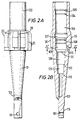
- Figs. 2A - 2C illustrate the body 10 and its bore 100.
- the body 10 has a top shoulder 105; an upper shoulder 104; a top cavity 106; an enlarged cavity 107; a plate shoulder 108; a mid-cavity 109; fluid flow ports 110; a lower piston shoulder 111; a lower shoulder 112; and a bottom shoulder 113.
- Ratchet teeth 116 are provided on a side of the lower end 103 of the body 10.
- the teeth 116 are profiled so that upon pushing down on the body 10 the teeth contact and engage teeth on a whipstock and downward force is transmitted to the whipstock via the teeth while the downward force is isolated from a shear stud (not shown) extending through a hole 101 in the body 10 into a pilot lug of the whipstock (not shown).
- the teeth 116 are also profiled so that in response to an upward pull on the body 10 there is no isolating engagement with the corresponding teeth on the pilot lug, the shear stud is not isolated from the force of such upward pulling, and the shear stud is shearable when enough upward force is applied, e.g. 9100 to 13600kg (twenty thousand to thirty thousand pounds).
- Figs. 3A and 3B show the top sub 90 which has a top end 122, a lower shoulder 123, and upper shoulder 125, and a mid-portion 120.
- a lower shoulder 126 abuts the top end 102 of the body 10 of the mill M.
- a portion of the top piston rod 30 extends into a fluid flow bore 125 of the top sub 90.
- Figs. 4A and 4B show the retaining plate 80 with a body 130 and a lower shoulder 132 (which rests against the upper shoulder 104 of the body 10, Fig. 1B) which has a hole 131 through which extends the top piston rod 30. Fluid flows through flow areas defined by arced portions 133 of the plate 80.
- Figs. 5A and 5B illustrate the shear sub 50 which has a body 140 with a top end 141, bottom end 142 and shear pin recesses 143.
- a fluid flow bore 145 extends through the body 140.
- a top shoulder 144 rests on a shoulder 164 of the top piston rod 30 (see Fig. 1B) to hold the shear sub 50 in place about the top piston rod 30.
- Figs. 6A and 6B show the labyrinth piston 40 which has a body 150, a top end 151, a bottom end 152, an inner shoulder 154, and a fluid flow bore 155 through the body 150.
- Controlled leakage around the labyrinth piston 40 is provided by one or more exterior labyrinth grooves 156 and interior labyrinth grooves 157.
- Shear pins 14 (Fig. 1B) extend into shear pin recesses 143 (Fig. 5A).
- An exterior surface 158 of the labyrinth piston 40 contacts an interior surface of the body 10 (see Fig. 1B) to confine clean fluid in the top cavity 106 of the body 10.
- Figs. 7A and 7B show the top piston rod 30 which has a body 160 with a top end 161, a shoulder 164, a bottom end 162 and a piston rod plate 163.
- the piston rod plate 163 rests against the plate shoulder 108 (see Fig. 1B) of the bore 100 of the body 10. Fluid flows past the piston rod plate 163 through flow areas defined by arced portions 165 of the plate 163.
- Figs. 8A and 8B show the lower piston 60 which has a body 170 with a top end 171, a bottom end 172 and a fluid flow bore 175 through the body 170.
- An 0-ring 182 (Fig. 1B) is positioned in a groove 173 and an 0-ring 181 (Fig. 1B) is positioned in a groove 174 (see Fig. 1B).
- Shear pins 16 (Fig. 1B) extend into shear pin recesses 180.
- a shoulder 176 moves to abut the lower piston shoulder 111 of the bore 100 of the body 10 and a shoulder 179 moves so that the ring 70 abuts the lower shoulder 112 of the bore 100 of the body 10 (Fig. 2B) to prevent further downward movement of the lower piston 60 as the bottom end 172 is received in a bottom portion 129 (see Fig. 1B) of the bore 100.
- Figs. 9A and 9B show the ring 70 which has a body 190 with a top end 191, a bottom end 192 and a fluid flow bore 195 through the body 190. Holes 193 receive the shear pins 16 (Fig. 1B) to initially prevent movement of the lower piston 60.
- the body 10 is provided with eight blades 20, but any desired number (one, two, three, four, etc.) may be used.
- Each blade 20 has three primary milling surfaces: a lower part 196; a mid-portion 197; and a top part 198. It is within the scope of this invention for any or all of these parts to be dressed with any known milling inserts, matrix material, or combination thereof in any known disposition, configuration, array, or pattern.
- a ring 70 is secured with shear pins 16 to the lower piston 60, the number of shear pins being well above the pressure at which the anchor is to be set.
- shear pins are made from, e.g., low carbon steel or brass; and the major parts of the mill are made from steel or alloy steel, e.g. 4140 steel.
- a male connector 120 is connected to a bottom of the mill body 10 and the mill body 10 is filled with clean fluid.
- the shear sub 50 is installed in and pinned to the labyrinth piston 40 and then the shear-sub-labyrinth-piston combination is slid onto the top piston rod 30.
- the weight of this combination may result in the displacement of fluid from within the body 10 across and out from above the labyrinth piston.
- an anchor packer is to be set at 2000 p.s.i.
- four shear pins are used which each shear at 875 p.s.i. and fluid at 3500 p.s.i. is circulated to shear the pins and insure setting of the packer.
- the retaining plate 80 is then installed on the top piston rod 30.
- a releasable retaining cap (made from e.g. plastic or aluminum) is placed over the mill body 10 for shipment and movement. The retaining cap is removed at a rig site.
- the mill M is then secured to a whipstock with a shear stud passing through the hole 101 and into a pilot lug of the whipstock.
- the bottom of the whipstock is connected to an anchor.
- the whole assembly is then introduced on a drill string into a cased wellbore filled with drilling fluid. If increased temperature is encountered as the assembly moves down in the drilling fluid, clean fluid leakage past the labyrinth piston increases to accommodate expanding clean fluid so that the anchor is not prematurely set.
- the labyrinth piston 40 also acts as a debris barrier to inhibit the hydraulic line from being clogged during anchor setting. Air anywhere in the system beneath the labyrinth piston 40 can escape up past the labyrinth so that the hydraulic line and other devices are filled with fluid. For a chamber of a volume of about forty cubic inches, about three cubic inches may leak out; and for a chamber with a volume of about one hundred cubic inches about nine cubic inches of fluid may leak out.
- Fig. 10 illustrates a milling system 200 with pieces of drill pipe 201 threadedly connected to drill collars 202 and heavy pipe 203.
- a watermelon mill 204 is threadedly connected to the heavy pipe 203 and a window mill 205 is threadedly connected to the watermelon mill 204.
- Fig. 11 discloses a retrieval system 220 which has drill pipes 221 threadedly connected to drill collars 222.
- An orientation indicating device 223 e.g. a measuring-while-drilling (MWD) device or a gyroscopic tool
- MWD measuring-while-drilling
- a jarring device 224 any conventional commercially available jar.
- a retrieval tool 225 with a hook 226 for insertion into a corresponding hole in a whipstock is connected to the jar 224.
- MWD measuring-while-drilling
- Fig. 12 shows a system 250 according to the present invention which has drill pipes 251, drill collars 252, an orientation sensor device 253, drill pipe 254, a cross-over sub 255, a starting mill 256 (like the mill M previously described), a whipstock 258 with a concave with a concave surface 257, an hydraulic fluid line 259 intercommunicating between the starting mill 256 and an hydraulically activated anchor (anchor device or anchor packer) at a pivot device 260 (pivot device as is well known in the art).
- Fig. 13A - 13D shows a whipstock 270 according to the present invention which has a top solid part 271 releasably connected to a hollow lower part 276.
- the top solid part 271 has a pilot lug 272, a retrieval hook hole 273, a concave inclined surface 275 and a rail 279.
- the lower hollow part 276 has an inner bore 277 shown filled with drillable filler material or cement 278. The cement is in the tool as it is inserted into the casing.
- the lower hollow part 276 has a concave inclined surface 280 which lines up with the concave inclined surface 275 of the top solid part 271. As shown in Fig.
- shear screws 281 extend through holes 283 in the lower hollow part 276 and holes 282 in the top solid part 271 to releasably hold the two parts together.
- the rail 279 is received in a corresponding groove 274 in the lower hollow part 276 to insure correct combination of the two parts.
- the length of the top solid part 271 is at least 50% of the length of the inclined portion of the concave.
- a whipstock 270 maybe used in the system 250 (Fig. 12) or any other system disclosed herein.
- the top solid part is released by shearing the shear screws with an upward pull on the whipstock, making retrieval and re-use of the top solid part possible.
- the bottom hollow part need never leave the wellbore and the cement 278 can easily be drilled out.
- Figs. 14A and 14B show a pilot lug 350 according to the present invention with a body 352 having a hole 354 therethrough through which a shear stud or bolt (not shown) extends to releasably secure another item (e.g. a mill) to the pilot lug.
- Ratchet teeth 356 on the pilot lug 350 co-act with corresponding teeth on another member (e.g. teeth 116, Fig. 1B) and operate, as described above, to isolate the shear stud from a downward force applied to a member (e.g. the mill of Fig. 1B) releasably secured by the shear stud to the pilot lug 350.
- the lug 272 (Fig. 13B) may have the teeth 356, as may any other pilot lug or member for attaching a mill to a whipstock.
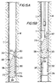
- Figs. 15A and 15B illustrate a whipstock 300 in a casing C in a wellbore.
- the whipstock 300 has an outer hollow tubular member 302 having a top end 303, a bottom end 304 and a central bore 305; and an inner solid member 306 with a top end 307, a bottom end 308, a concave 309 with a concave inclined surface 310, and a retrieval hook slot 311 in the concave 309.
- the hollow tubular member 302 is secured to the casing and, while in use, the inner solid member 306 is releasably secured to the outer hollow tubular member 302, e.g. by shear pins 312 extending from the inner solid member 306 into the outer hollow tubular member 302.
- the retrieval tool T is used to remove the inner solid member 306 for re-use.
Landscapes
- Engineering & Computer Science (AREA)
- Geology (AREA)
- Life Sciences & Earth Sciences (AREA)
- Mining & Mineral Resources (AREA)
- Environmental & Geological Engineering (AREA)
- Fluid Mechanics (AREA)
- Physics & Mathematics (AREA)
- General Life Sciences & Earth Sciences (AREA)
- Geochemistry & Mineralogy (AREA)
- Mechanical Engineering (AREA)
- Earth Drilling (AREA)
- Crushing And Grinding (AREA)
- Excavating Of Shafts Or Tunnels (AREA)
Claims (13)
- Fraise destinée à des opérations de fraisage dans un trou de forage, comportant un moyen pour actionner un élément au-dessous de la fraise, la fraise comprenant un corps (10) avec un alésage (100) le traversant, pour assurer l'écoulement de fluide à travers ladite fraise, au moins une surface de fraisage sur le corps, un dispositif de régulation de l'écoulement dans le corps pour assurer une régulation sélective de l'écoulement du fluide à travers la fraise, caractérisée en ce que ledit dispositif de régulation de l'écoulement englobe un premier dispositif de régulation de l'écoulement (14, 40, 120, 185) pouvant être actionné par le fluide à une première pression de fluide pour permettre l'actionnement de l'élément au-dessous de la fraise par le fluide à la première pression.
- Fraise selon la revendication 1, comprenant en outre une quantité de fluide propre dans l'alésage.
- Fraise selon la revendication 2, comprenant en outre un dispositif de fuite pour assurer une fuite contrôlée d'une partie de la quantité de fluide propre de la fraise.
- Fraise selon la revendication 3, dans laquelle le dispositif de fuite comprend un piston à labyrinthe agencé de manière mobile dans ledit corps de la fraise.
- Fraise selon l'une quelconque des revendications précédentes, dans laquelle la fraise est une fraise d'amorçage, l'élément au-dessous de la fraise étant une ancre.
- Fraise selon l'une quelconque des revendications précédentes, dans laquelle la fraise d'amorçage est connectée de manière amovible à un sifflet déviateur, l'ancre étant fixée à une partie inférieure du sifflet déviateur.
- Fraise selon l'une quelconque des revendications précédentes, dans laquelle ledit dispositif de régulation de l'écoulement englobe un deuxième dispositif de régulation de l'écoulement (16, 60) pouvant être actionné à une deuxième pression de fluide et pouvant être déplacé en réponse à celle-ci pour permettre l'écoulement du fluide en-dehors d'au moins un orifice (110) adjacent à une partie de fraisage de la fraise, la deuxième pression de fluide étant supérieure à la première pression de fluide.
- Fraise selon l'une quelconque des revendications précédentes, comprenant en outre un élément à cisaillement connectant de manière amovible la fraise à un autre élément, et un dispositif d'isolation sur la fraise pour isoler l'élément à cisaillement d'une force descendante appliquée à la fraise.
- Fraise selon la revendication 8, dans laquelle le dispositif d'isolation comprend des dents profilées sur le corps de la fraise, destinées à contacter des dents correspondantes sur un autre élément et à s'engager dans celles-ci, les dents profilées étant agencées et configurées de sorte qu'une force descendante appliquée à la fraise est transférée à l'autre élément par l'engagement des dents profilées dans les dents correspondantes, une force ascendante appliquée à la fraise étant transférée à l'élément de cisaillement connectant de manière amovible la fraise à l'autre élément.
- Fraise selon les revendications 8 ou 9, dans laquelle ledit autre élément est un sifflet déviateur comportant une partie supérieure concave, l'élément à cisaillement étant un goujon de cisaillement connectant la fraise à la partie concave du sifflet déviateur.
- Fraise selon l'une quelconque des revendications précédentes, dans laquelle la au moins une surface de fraisage comprend plusieurs lames de fraisage sur le corps de la fraise.
- Procédé d'installation d'un système de fraisage dans un trou de forage garni d'un tubage, le système de fraisage comportant une fraise connectée de manière amovible à un sifflet déviateur et une ancre connectée au sifflet déviateur, la fraise comprenant un corps avec un alésage le traversant pour assurer l'écoulement de fluide à travers la fraise, au moins une surface de fraisage sur le corps, et un dispositif de régulation de l'écoulement dans le corps pour assurer une régulation sélective de l'écoulement de fluide à travers la fraise, le dispositif de régulation de l'écoulement englobant un premier dispositif de régulation de l'écoulement pouvant être actionné par le fluide à une première pression de fluide pour permettre l'écoulement du fluide à la première pression à partir de la fraise pour actionner l'ancre, le procédé comprenant l'insertion du système de fraisage dans le tubage et l'écoulement de fluide à la première pression de fluide à travers la fraise et à travers le premier dispositif de régulation de l'écoulement vers l'ancre pour mettre en place l'ancre dans le tubage.
- Procédé selon la revendication 12, dans lequel la fraise comprend en outre une quantité de fluide confinée dans l'alésage avant l'insertion de la fraise dans le trou de forage et un dispositif de fuite pour assurer une fuite contrôlée d'une partie de la quantité de fluide de la fraise.
Applications Claiming Priority (3)
| Application Number | Priority Date | Filing Date | Title |
|---|---|---|---|
| US08/542,439 US5720349A (en) | 1995-10-12 | 1995-10-12 | Starting mill and operations |
| US542439 | 1995-10-12 | ||
| PCT/GB1996/002510 WO1997013954A2 (fr) | 1995-10-12 | 1996-10-14 | Fraise servant a effectuer des operations de fraisage dans un puits de forage |
Publications (2)
| Publication Number | Publication Date |
|---|---|
| EP0888490A2 EP0888490A2 (fr) | 1999-01-07 |
| EP0888490B1 true EP0888490B1 (fr) | 2001-06-06 |
Family
ID=24163845
Family Applications (1)
| Application Number | Title | Priority Date | Filing Date |
|---|---|---|---|
| EP96934987A Expired - Lifetime EP0888490B1 (fr) | 1995-10-12 | 1996-10-14 | Fraise servant a effectuer des operations de fraisage dans un puits de forage |
Country Status (7)
| Country | Link |
|---|---|
| US (1) | US5720349A (fr) |
| EP (1) | EP0888490B1 (fr) |
| AU (1) | AU719893B2 (fr) |
| CA (1) | CA2234689C (fr) |
| DE (1) | DE69613242T2 (fr) |
| NO (1) | NO981666L (fr) |
| WO (1) | WO1997013954A2 (fr) |
Families Citing this family (19)
| Publication number | Priority date | Publication date | Assignee | Title |
|---|---|---|---|---|
| US6170576B1 (en) * | 1995-09-22 | 2001-01-09 | Weatherford/Lamb, Inc. | Mills for wellbore operations |
| US5829531A (en) * | 1996-01-31 | 1998-11-03 | Smith International, Inc. | Mechanical set anchor with slips pocket |
| US6032740A (en) * | 1998-01-23 | 2000-03-07 | Weatherford/Lamb, Inc. | Hook mill systems |
| GB9907116D0 (en) * | 1999-03-26 | 1999-05-19 | Smith International | Whipstock casing milling system |
| CA2288494C (fr) | 1999-10-22 | 2008-01-08 | Smith International Canada, Ltd. | Systeme de broyage a mouvement unique |
| US6715567B2 (en) | 2001-05-02 | 2004-04-06 | Weatherford/Lamb, Inc. | Apparatus and method for forming a pilot hole in a formation |
| US6779600B2 (en) | 2001-07-27 | 2004-08-24 | Baker Hughes Incorporated | Labyrinth lock seal for hydrostatically set packer |
| US7487835B2 (en) * | 2004-05-20 | 2009-02-10 | Weatherford/Lamb, Inc. | Method of developing a re-entry into a parent wellbore from a lateral wellbore, and bottom hole assembly for milling |
| US8127858B2 (en) * | 2008-12-18 | 2012-03-06 | Baker Hughes Incorporated | Open-hole anchor for whipstock system |
| US9404331B2 (en) | 2012-07-31 | 2016-08-02 | Smith International, Inc. | Extended duration section mill and methods of use |
| US10006264B2 (en) | 2014-05-29 | 2018-06-26 | Weatherford Technology Holdings, Llc | Whipstock assembly having anchor and eccentric packer |
| US10871034B2 (en) | 2016-02-26 | 2020-12-22 | Halliburton Energy Services, Inc. | Whipstock assembly with a support member |
| US10119350B2 (en) | 2016-05-26 | 2018-11-06 | Baker Hughes, A Ge Company, Llc | Expandable junk mill |
| US10151163B2 (en) | 2016-08-22 | 2018-12-11 | Baker Hughes, A Ge Company, Llc | Expandable junk mill stabilizer |
| AU2016425343B2 (en) | 2016-09-27 | 2021-09-09 | Halliburton Energy Services, Inc. | Whipstock assemblies with a retractable tension arm |
| US11333004B2 (en) | 2020-06-03 | 2022-05-17 | Weatherford Technology Holdings, Llc | Piston initiator for sidetrack assembly |
| US11053741B1 (en) * | 2020-06-05 | 2021-07-06 | Weatherford Technology Holdings, Llc | Sidetrack assembly with replacement mill head for open hole whipstock |
| US11585155B2 (en) * | 2021-06-04 | 2023-02-21 | Baker Hughes Oilfield Operations Llc | Mill, downhole tool with mill, method and system |
| US12607096B2 (en) * | 2023-09-28 | 2026-04-21 | Halliburton Energy Services, Inc. | Multilateral whipstock assembly employing degradable material |
Family Cites Families (31)
| Publication number | Priority date | Publication date | Assignee | Title |
|---|---|---|---|---|
| US1570518A (en) * | 1919-03-26 | 1926-01-19 | Sullivan Machinery Co | Method and apparatus for drilling holes |
| US2807440A (en) * | 1953-08-10 | 1957-09-24 | J E Hill | Directional window cutter for whipstocks |
| US2885182A (en) * | 1956-09-24 | 1959-05-05 | Driltrol | Drilling and deflecting tool |
| US3095039A (en) * | 1960-10-07 | 1963-06-25 | Bowen Itco Inc | Whipstock and anchoring mechanism therefor |
| US3908759A (en) * | 1974-05-22 | 1975-09-30 | Standard Oil Co | Sidetracking tool |
| US4182423A (en) * | 1978-03-02 | 1980-01-08 | Burton/Hawks Inc. | Whipstock and method for directional well drilling |
| US4324299A (en) * | 1980-07-18 | 1982-04-13 | Maurer Engineering, Inc. | Downhole drilling motor with pressure balanced bearing seals |
| US4415205A (en) * | 1981-07-10 | 1983-11-15 | Rehm William A | Triple branch completion with separate drilling and completion templates |
| US4938291A (en) * | 1986-01-06 | 1990-07-03 | Lynde Gerald D | Cutting tool for cutting well casing |
| US4978260A (en) * | 1986-01-06 | 1990-12-18 | Tri-State Oil Tools, Inc. | Cutting tool for removing materials from well bore |
| US5373900A (en) * | 1988-04-15 | 1994-12-20 | Baker Hughes Incorporated | Downhole milling tool |
| US4887668A (en) * | 1986-01-06 | 1989-12-19 | Tri-State Oil Tool Industries, Inc. | Cutting tool for cutting well casing |
| US5150755A (en) * | 1986-01-06 | 1992-09-29 | Baker Hughes Incorporated | Milling tool and method for milling multiple casing strings |
| US5038859A (en) * | 1988-04-15 | 1991-08-13 | Tri-State Oil Tools, Inc. | Cutting tool for removing man-made members from well bore |
| US5014778A (en) * | 1986-01-06 | 1991-05-14 | Tri-State Oil Tools, Inc. | Milling tool for cutting well casing |
| US4796709A (en) * | 1986-01-06 | 1989-01-10 | Tri-State Oil Tool Industries, Inc. | Milling tool for cutting well casing |
| US5086838A (en) * | 1986-01-06 | 1992-02-11 | Baker Hughes Incorporated | Tapered cutting tool for reaming tubular members in well bore |
| US4807704A (en) * | 1987-09-28 | 1989-02-28 | Atlantic Richfield Company | System and method for providing multiple wells from a single wellbore |
| US5035292A (en) * | 1989-01-11 | 1991-07-30 | Masx Energy Service Group, Inc. | Whipstock starter mill with pressure drop tattletale |
| GB9003047D0 (en) * | 1990-02-10 | 1990-04-11 | Tri State Oil Tool Uk | Insert type window mill |
| US5522461A (en) * | 1995-03-31 | 1996-06-04 | Weatherford U.S., Inc. | Mill valve |
| US5452759A (en) * | 1993-09-10 | 1995-09-26 | Weatherford U.S., Inc. | Whipstock system |
| US5425417A (en) * | 1993-09-10 | 1995-06-20 | Weatherford U.S., Inc. | Wellbore tool setting system |
| US5429187A (en) * | 1994-03-18 | 1995-07-04 | Weatherford U.S., Inc. | Milling tool and operations |
| US5425419A (en) * | 1994-02-25 | 1995-06-20 | Sieber; Bobby G. | Whipstock apparatus and methods of use |
| US5392862A (en) * | 1994-02-28 | 1995-02-28 | Smith International, Inc. | Flow control sub for hydraulic expanding downhole tools |
| US5431220A (en) * | 1994-03-24 | 1995-07-11 | Smith International, Inc. | Whipstock starter mill assembly |
| US5379845A (en) * | 1994-06-06 | 1995-01-10 | Atlantic Richfield Company | Method for setting a whipstock in a wellbore |
| US5445222A (en) * | 1994-06-07 | 1995-08-29 | Shell Oil Company | Whipstock and staged sidetrack mill |
| US5443129A (en) * | 1994-07-22 | 1995-08-22 | Smith International, Inc. | Apparatus and method for orienting and setting a hydraulically-actuatable tool in a borehole |
| US5551509A (en) * | 1995-03-24 | 1996-09-03 | Tiw Corporation | Whipstock and starter mill |
-
1995
- 1995-10-12 US US08/542,439 patent/US5720349A/en not_active Expired - Lifetime
-
1996
- 1996-10-14 DE DE69613242T patent/DE69613242T2/de not_active Expired - Fee Related
- 1996-10-14 WO PCT/GB1996/002510 patent/WO1997013954A2/fr not_active Ceased
- 1996-10-14 CA CA002234689A patent/CA2234689C/fr not_active Expired - Lifetime
- 1996-10-14 EP EP96934987A patent/EP0888490B1/fr not_active Expired - Lifetime
- 1996-10-14 AU AU73096/96A patent/AU719893B2/en not_active Ceased
-
1998
- 1998-04-14 NO NO981666A patent/NO981666L/no not_active Application Discontinuation
Also Published As
| Publication number | Publication date |
|---|---|
| CA2234689A1 (fr) | 1997-04-17 |
| WO1997013954A2 (fr) | 1997-04-17 |
| NO981666D0 (no) | 1998-04-14 |
| WO1997013954A3 (fr) | 1997-06-26 |
| NO981666L (no) | 1998-05-28 |
| CA2234689C (fr) | 2004-12-28 |
| EP0888490A2 (fr) | 1999-01-07 |
| AU719893B2 (en) | 2000-05-18 |
| AU7309696A (en) | 1997-04-30 |
| US5720349A (en) | 1998-02-24 |
| DE69613242D1 (de) | 2001-07-12 |
| DE69613242T2 (de) | 2002-05-16 |
Similar Documents
| Publication | Publication Date | Title |
|---|---|---|
| EP0888490B1 (fr) | Fraise servant a effectuer des operations de fraisage dans un puits de forage | |
| CA2796454C (fr) | Appareil a sifflet deviateur pour cimentation et procedes | |
| CA2271795C (fr) | Sifflet deviateur | |
| CA2411363C (fr) | Appareil et procede permettant de realiser un raccordement multilateral | |
| US7640984B2 (en) | Method for drilling and casing a wellbore with a pump down cement float | |
| AU730521B2 (en) | Tool and method for drilling a lateral well | |
| US7448446B2 (en) | Thru tubing tool and method | |
| US6554062B1 (en) | Anchor apparatus and method | |
| EP3821105B1 (fr) | Appareil et procédé de formation d'un puits de forage latéral | |
| WO2012142543A2 (fr) | Système et procédé d'accouplement d'un trépan de forage imprégné à un sifflet de déviation | |
| CA2915624C (fr) | Ensemble d'outil et procede de forage de puits ramifies ou multilateraux a l'aide de sifflet deviateur | |
| CA2221435A1 (fr) | Methode d'installation d'un sifflet deviateur et de cimentation sous pression en une seule operation | |
| CA2865051A1 (fr) | Appareil sifflet deviateur de cimentation et methodes | |
| US9151136B2 (en) | Cementing whipstock apparatus and methods | |
| US5318132A (en) | Retrievable whipstock/packer assembly and method of use | |
| US6786283B2 (en) | Methods and associated apparatus for drilling and completing a wellbore junction | |
| CA2493990A1 (fr) | Nouveau procede ameliore et appareil comprenant un guide de sortie et un laminoir a profiles combines, integres ou autre pour la deviation ou le sondage devie a partir de puits de forage existants | |
| US6464001B1 (en) | Multilateral wellbore system | |
| WO2001053650A1 (fr) | Procede et dispositif de forage devie a guide sortie combine a la fraise de section | |
| EP4347990B1 (fr) | Trépan de récupération de sifflet déviateur |
Legal Events
| Date | Code | Title | Description |
|---|---|---|---|
| PUAI | Public reference made under article 153(3) epc to a published international application that has entered the european phase |
Free format text: ORIGINAL CODE: 0009012 |
|
| 17P | Request for examination filed |
Effective date: 19980414 |
|
| AK | Designated contracting states |
Kind code of ref document: A2 Designated state(s): DE FR GB IT NL |
|
| RBV | Designated contracting states (corrected) |
Designated state(s): DE FR GB IT NL |
|
| 17Q | First examination report despatched |
Effective date: 19991104 |
|
| GRAG | Despatch of communication of intention to grant |
Free format text: ORIGINAL CODE: EPIDOS AGRA |
|
| GRAG | Despatch of communication of intention to grant |
Free format text: ORIGINAL CODE: EPIDOS AGRA |
|
| GRAH | Despatch of communication of intention to grant a patent |
Free format text: ORIGINAL CODE: EPIDOS IGRA |
|
| GRAH | Despatch of communication of intention to grant a patent |
Free format text: ORIGINAL CODE: EPIDOS IGRA |
|
| GRAA | (expected) grant |
Free format text: ORIGINAL CODE: 0009210 |
|
| AK | Designated contracting states |
Kind code of ref document: B1 Designated state(s): DE FR GB IT NL |
|
| PG25 | Lapsed in a contracting state [announced via postgrant information from national office to epo] |
Ref country code: IT Free format text: LAPSE BECAUSE OF FAILURE TO SUBMIT A TRANSLATION OF THE DESCRIPTION OR TO PAY THE FEE WITHIN THE PRE;WARNING: LAPSES OF ITALIAN PATENTS WITH EFFECTIVE DATE BEFORE 2007 MAY HAVE OCCURRED AT ANY TIME BEFORE 2007. THE CORRECT EFFECTIVE DATE MAY BE DIFFERENT FROM THE ONE RECORDED.SCRIBED TIME-LIMIT Effective date: 20010606 |
|
| REF | Corresponds to: |
Ref document number: 69613242 Country of ref document: DE Date of ref document: 20010712 |
|
| ET | Fr: translation filed | ||
| REG | Reference to a national code |
Ref country code: GB Ref legal event code: IF02 |
|
| PLBE | No opposition filed within time limit |
Free format text: ORIGINAL CODE: 0009261 |
|
| STAA | Information on the status of an ep patent application or granted ep patent |
Free format text: STATUS: NO OPPOSITION FILED WITHIN TIME LIMIT |
|
| 26N | No opposition filed | ||
| PGFP | Annual fee paid to national office [announced via postgrant information from national office to epo] |
Ref country code: FR Payment date: 20031003 Year of fee payment: 8 |
|
| PGFP | Annual fee paid to national office [announced via postgrant information from national office to epo] |
Ref country code: NL Payment date: 20031008 Year of fee payment: 8 |
|
| PGFP | Annual fee paid to national office [announced via postgrant information from national office to epo] |
Ref country code: DE Payment date: 20031023 Year of fee payment: 8 |
|
| PG25 | Lapsed in a contracting state [announced via postgrant information from national office to epo] |
Ref country code: NL Free format text: LAPSE BECAUSE OF NON-PAYMENT OF DUE FEES Effective date: 20050501 |
|
| PG25 | Lapsed in a contracting state [announced via postgrant information from national office to epo] |
Ref country code: DE Free format text: LAPSE BECAUSE OF NON-PAYMENT OF DUE FEES Effective date: 20050503 |
|
| PG25 | Lapsed in a contracting state [announced via postgrant information from national office to epo] |
Ref country code: FR Free format text: LAPSE BECAUSE OF NON-PAYMENT OF DUE FEES Effective date: 20050630 |
|
| NLV4 | Nl: lapsed or anulled due to non-payment of the annual fee |
Effective date: 20050501 |
|
| REG | Reference to a national code |
Ref country code: FR Ref legal event code: ST |
|
| REG | Reference to a national code |
Ref country code: GB Ref legal event code: 732E Free format text: REGISTERED BETWEEN 20151022 AND 20151028 |
|
| PGFP | Annual fee paid to national office [announced via postgrant information from national office to epo] |
Ref country code: GB Payment date: 20151014 Year of fee payment: 20 |
|
| REG | Reference to a national code |
Ref country code: GB Ref legal event code: PE20 Expiry date: 20161013 |
|
| PG25 | Lapsed in a contracting state [announced via postgrant information from national office to epo] |
Ref country code: GB Free format text: LAPSE BECAUSE OF EXPIRATION OF PROTECTION Effective date: 20161013 |