EP0888493B1 - Schalldämpfer-anordnung - Google Patents
Schalldämpfer-anordnung Download PDFInfo
- Publication number
- EP0888493B1 EP0888493B1 EP97908253A EP97908253A EP0888493B1 EP 0888493 B1 EP0888493 B1 EP 0888493B1 EP 97908253 A EP97908253 A EP 97908253A EP 97908253 A EP97908253 A EP 97908253A EP 0888493 B1 EP0888493 B1 EP 0888493B1
- Authority
- EP
- European Patent Office
- Prior art keywords
- arrangement according
- chamber
- silencer
- silencer arrangement
- shell housing
- Prior art date
- Legal status (The legal status is an assumption and is not a legal conclusion. Google has not performed a legal analysis and makes no representation as to the accuracy of the status listed.)
- Expired - Lifetime
Links
Images

Classifications
-
- F—MECHANICAL ENGINEERING; LIGHTING; HEATING; WEAPONS; BLASTING
- F01—MACHINES OR ENGINES IN GENERAL; ENGINE PLANTS IN GENERAL; STEAM ENGINES
- F01N—GAS-FLOW SILENCERS OR EXHAUST APPARATUS FOR MACHINES OR ENGINES IN GENERAL; GAS-FLOW SILENCERS OR EXHAUST APPARATUS FOR INTERNAL-COMBUSTION ENGINES
- F01N1/00—Silencing apparatus characterised by method of silencing
- F01N1/02—Silencing apparatus characterised by method of silencing by using resonance
- F01N1/023—Helmholtz resonators
-
- F—MECHANICAL ENGINEERING; LIGHTING; HEATING; WEAPONS; BLASTING
- F01—MACHINES OR ENGINES IN GENERAL; ENGINE PLANTS IN GENERAL; STEAM ENGINES
- F01N—GAS-FLOW SILENCERS OR EXHAUST APPARATUS FOR MACHINES OR ENGINES IN GENERAL; GAS-FLOW SILENCERS OR EXHAUST APPARATUS FOR INTERNAL-COMBUSTION ENGINES
- F01N13/00—Exhaust or silencing apparatus characterised by constructional features
- F01N13/18—Construction facilitating manufacture, assembly, or disassembly
- F01N13/1888—Construction facilitating manufacture, assembly, or disassembly the housing of the assembly consisting of two or more parts, e.g. two half-shells
-
- F—MECHANICAL ENGINEERING; LIGHTING; HEATING; WEAPONS; BLASTING
- F01—MACHINES OR ENGINES IN GENERAL; ENGINE PLANTS IN GENERAL; STEAM ENGINES
- F01N—GAS-FLOW SILENCERS OR EXHAUST APPARATUS FOR MACHINES OR ENGINES IN GENERAL; GAS-FLOW SILENCERS OR EXHAUST APPARATUS FOR INTERNAL-COMBUSTION ENGINES
- F01N3/00—Exhaust or silencing apparatus having means for purifying, rendering innocuous, or otherwise treating exhaust
- F01N3/08—Exhaust or silencing apparatus having means for purifying, rendering innocuous, or otherwise treating exhaust for rendering innocuous
- F01N3/10—Exhaust or silencing apparatus having means for purifying, rendering innocuous, or otherwise treating exhaust for rendering innocuous by thermal or catalytic conversion of noxious components of exhaust
- F01N3/24—Exhaust or silencing apparatus having means for purifying, rendering innocuous, or otherwise treating exhaust for rendering innocuous by thermal or catalytic conversion of noxious components of exhaust characterised by constructional aspects of converting apparatus
- F01N3/28—Construction of catalytic reactors
- F01N3/2882—Catalytic reactors combined or associated with other devices, e.g. exhaust silencers or other exhaust purification devices
- F01N3/2885—Catalytic reactors combined or associated with other devices, e.g. exhaust silencers or other exhaust purification devices with exhaust silencers in a single housing
-
- F—MECHANICAL ENGINEERING; LIGHTING; HEATING; WEAPONS; BLASTING
- F01—MACHINES OR ENGINES IN GENERAL; ENGINE PLANTS IN GENERAL; STEAM ENGINES
- F01N—GAS-FLOW SILENCERS OR EXHAUST APPARATUS FOR MACHINES OR ENGINES IN GENERAL; GAS-FLOW SILENCERS OR EXHAUST APPARATUS FOR INTERNAL-COMBUSTION ENGINES
- F01N1/00—Silencing apparatus characterised by method of silencing
-
- F—MECHANICAL ENGINEERING; LIGHTING; HEATING; WEAPONS; BLASTING
- F01—MACHINES OR ENGINES IN GENERAL; ENGINE PLANTS IN GENERAL; STEAM ENGINES
- F01N—GAS-FLOW SILENCERS OR EXHAUST APPARATUS FOR MACHINES OR ENGINES IN GENERAL; GAS-FLOW SILENCERS OR EXHAUST APPARATUS FOR INTERNAL-COMBUSTION ENGINES
- F01N1/00—Silencing apparatus characterised by method of silencing
- F01N1/02—Silencing apparatus characterised by method of silencing by using resonance
-
- F—MECHANICAL ENGINEERING; LIGHTING; HEATING; WEAPONS; BLASTING
- F01—MACHINES OR ENGINES IN GENERAL; ENGINE PLANTS IN GENERAL; STEAM ENGINES
- F01N—GAS-FLOW SILENCERS OR EXHAUST APPARATUS FOR MACHINES OR ENGINES IN GENERAL; GAS-FLOW SILENCERS OR EXHAUST APPARATUS FOR INTERNAL-COMBUSTION ENGINES
- F01N1/00—Silencing apparatus characterised by method of silencing
- F01N1/24—Silencing apparatus characterised by method of silencing by using sound-absorbing materials
-
- F—MECHANICAL ENGINEERING; LIGHTING; HEATING; WEAPONS; BLASTING
- F01—MACHINES OR ENGINES IN GENERAL; ENGINE PLANTS IN GENERAL; STEAM ENGINES
- F01N—GAS-FLOW SILENCERS OR EXHAUST APPARATUS FOR MACHINES OR ENGINES IN GENERAL; GAS-FLOW SILENCERS OR EXHAUST APPARATUS FOR INTERNAL-COMBUSTION ENGINES
- F01N13/00—Exhaust or silencing apparatus characterised by constructional features
- F01N13/14—Exhaust or silencing apparatus characterised by constructional features having thermal insulation
-
- F—MECHANICAL ENGINEERING; LIGHTING; HEATING; WEAPONS; BLASTING
- F01—MACHINES OR ENGINES IN GENERAL; ENGINE PLANTS IN GENERAL; STEAM ENGINES
- F01N—GAS-FLOW SILENCERS OR EXHAUST APPARATUS FOR MACHINES OR ENGINES IN GENERAL; GAS-FLOW SILENCERS OR EXHAUST APPARATUS FOR INTERNAL-COMBUSTION ENGINES
- F01N2260/00—Exhaust treating devices having provisions not otherwise provided for
- F01N2260/18—Exhaust treating devices having provisions not otherwise provided for for improving rigidity, e.g. by wings, ribs
-
- F—MECHANICAL ENGINEERING; LIGHTING; HEATING; WEAPONS; BLASTING
- F01—MACHINES OR ENGINES IN GENERAL; ENGINE PLANTS IN GENERAL; STEAM ENGINES
- F01N—GAS-FLOW SILENCERS OR EXHAUST APPARATUS FOR MACHINES OR ENGINES IN GENERAL; GAS-FLOW SILENCERS OR EXHAUST APPARATUS FOR INTERNAL-COMBUSTION ENGINES
- F01N2450/00—Methods or apparatus for fitting, inserting or repairing different elements
- F01N2450/20—Methods or apparatus for fitting, inserting or repairing different elements by mechanical joints, e.g. by deforming housing, tube, baffle plate or parts thereof
-
- F—MECHANICAL ENGINEERING; LIGHTING; HEATING; WEAPONS; BLASTING
- F01—MACHINES OR ENGINES IN GENERAL; ENGINE PLANTS IN GENERAL; STEAM ENGINES
- F01N—GAS-FLOW SILENCERS OR EXHAUST APPARATUS FOR MACHINES OR ENGINES IN GENERAL; GAS-FLOW SILENCERS OR EXHAUST APPARATUS FOR INTERNAL-COMBUSTION ENGINES
- F01N2450/00—Methods or apparatus for fitting, inserting or repairing different elements
- F01N2450/22—Methods or apparatus for fitting, inserting or repairing different elements by welding or brazing
-
- F—MECHANICAL ENGINEERING; LIGHTING; HEATING; WEAPONS; BLASTING
- F01—MACHINES OR ENGINES IN GENERAL; ENGINE PLANTS IN GENERAL; STEAM ENGINES
- F01N—GAS-FLOW SILENCERS OR EXHAUST APPARATUS FOR MACHINES OR ENGINES IN GENERAL; GAS-FLOW SILENCERS OR EXHAUST APPARATUS FOR INTERNAL-COMBUSTION ENGINES
- F01N2470/00—Structure or shape of exhaust gas passages, pipes or tubes
- F01N2470/02—Tubes being perforated
- F01N2470/04—Tubes being perforated characterised by shape, disposition or dimensions of apertures
-
- F—MECHANICAL ENGINEERING; LIGHTING; HEATING; WEAPONS; BLASTING
- F01—MACHINES OR ENGINES IN GENERAL; ENGINE PLANTS IN GENERAL; STEAM ENGINES
- F01N—GAS-FLOW SILENCERS OR EXHAUST APPARATUS FOR MACHINES OR ENGINES IN GENERAL; GAS-FLOW SILENCERS OR EXHAUST APPARATUS FOR INTERNAL-COMBUSTION ENGINES
- F01N2470/00—Structure or shape of exhaust gas passages, pipes or tubes
- F01N2470/18—Structure or shape of exhaust gas passages, pipes or tubes the axis of inlet or outlet tubes being other than the longitudinal axis of apparatus
-
- F—MECHANICAL ENGINEERING; LIGHTING; HEATING; WEAPONS; BLASTING
- F01—MACHINES OR ENGINES IN GENERAL; ENGINE PLANTS IN GENERAL; STEAM ENGINES
- F01N—GAS-FLOW SILENCERS OR EXHAUST APPARATUS FOR MACHINES OR ENGINES IN GENERAL; GAS-FLOW SILENCERS OR EXHAUST APPARATUS FOR INTERNAL-COMBUSTION ENGINES
- F01N2470/00—Structure or shape of exhaust gas passages, pipes or tubes
- F01N2470/30—Tubes with restrictions, i.e. venturi or the like, e.g. for sucking air or measuring mass flow
-
- F—MECHANICAL ENGINEERING; LIGHTING; HEATING; WEAPONS; BLASTING
- F01—MACHINES OR ENGINES IN GENERAL; ENGINE PLANTS IN GENERAL; STEAM ENGINES
- F01N—GAS-FLOW SILENCERS OR EXHAUST APPARATUS FOR MACHINES OR ENGINES IN GENERAL; GAS-FLOW SILENCERS OR EXHAUST APPARATUS FOR INTERNAL-COMBUSTION ENGINES
- F01N2490/00—Structure, disposition or shape of gas-chambers
- F01N2490/15—Plurality of resonance or dead chambers
- F01N2490/155—Plurality of resonance or dead chambers being disposed one after the other in flow direction
-
- F—MECHANICAL ENGINEERING; LIGHTING; HEATING; WEAPONS; BLASTING
- F01—MACHINES OR ENGINES IN GENERAL; ENGINE PLANTS IN GENERAL; STEAM ENGINES
- F01N—GAS-FLOW SILENCERS OR EXHAUST APPARATUS FOR MACHINES OR ENGINES IN GENERAL; GAS-FLOW SILENCERS OR EXHAUST APPARATUS FOR INTERNAL-COMBUSTION ENGINES
- F01N2490/00—Structure, disposition or shape of gas-chambers
- F01N2490/20—Chambers being formed inside the exhaust pipe without enlargement of the cross section of the pipe, e.g. resonance chambers
-
- F—MECHANICAL ENGINEERING; LIGHTING; HEATING; WEAPONS; BLASTING
- F01—MACHINES OR ENGINES IN GENERAL; ENGINE PLANTS IN GENERAL; STEAM ENGINES
- F01N—GAS-FLOW SILENCERS OR EXHAUST APPARATUS FOR MACHINES OR ENGINES IN GENERAL; GAS-FLOW SILENCERS OR EXHAUST APPARATUS FOR INTERNAL-COMBUSTION ENGINES
- F01N3/00—Exhaust or silencing apparatus having means for purifying, rendering innocuous, or otherwise treating exhaust
- F01N3/08—Exhaust or silencing apparatus having means for purifying, rendering innocuous, or otherwise treating exhaust for rendering innocuous
- F01N3/10—Exhaust or silencing apparatus having means for purifying, rendering innocuous, or otherwise treating exhaust for rendering innocuous by thermal or catalytic conversion of noxious components of exhaust
- F01N3/24—Exhaust or silencing apparatus having means for purifying, rendering innocuous, or otherwise treating exhaust for rendering innocuous by thermal or catalytic conversion of noxious components of exhaust characterised by constructional aspects of converting apparatus
- F01N3/28—Construction of catalytic reactors
- F01N3/2839—Arrangements for mounting catalyst support in housing, e.g. with means for compensating thermal expansion or vibration
-
- Y—GENERAL TAGGING OF NEW TECHNOLOGICAL DEVELOPMENTS; GENERAL TAGGING OF CROSS-SECTIONAL TECHNOLOGIES SPANNING OVER SEVERAL SECTIONS OF THE IPC; TECHNICAL SUBJECTS COVERED BY FORMER USPC CROSS-REFERENCE ART COLLECTIONS [XRACs] AND DIGESTS
- Y02—TECHNOLOGIES OR APPLICATIONS FOR MITIGATION OR ADAPTATION AGAINST CLIMATE CHANGE
- Y02A—TECHNOLOGIES FOR ADAPTATION TO CLIMATE CHANGE
- Y02A50/00—TECHNOLOGIES FOR ADAPTATION TO CLIMATE CHANGE in human health protection, e.g. against extreme weather
- Y02A50/20—Air quality improvement or preservation, e.g. vehicle emission control or emission reduction by using catalytic converters
Definitions
- the invention relates to a silencer arrangement Multi-chamber construction silencers, especially for passenger vehicles, with one composed of two half shells Housing in which a catalyst module is integrated is recorded.
- An exhaust system of a motor vehicle is known to have the task involved in the combustion of the fresh mixture in the Exhaust gases generated by the engine with low flow resistance derive and exit at a certain point of the vehicle to let that often prescribed by law is.
- the exhaust system has a silencer arrangement, for a low-emission emission of the exhaust gases Emission control device, a so-called catalyst.
- the catalyst occurs in such a known system combined in the exhaust line mostly in the place of the front silencer the silencer arrangement and is the rear silencer, if necessary, upstream of the center silencer.
- catalyst carrier with its precious metal coating, preferably a monolith, and its housing.
- precious metal coating preferably a monolith
- One and Output funnels can be provided.
- the invention has for its object a silencer arrangement of the type mentioned at the beginning, which is simple, can be operated effectively and especially for very small motor vehicles with a 3-cylinder engine suitable is.
- the silencer arrangement is advantageously further developed by the features according to claims 2 to 29.
- a silencer system partition forms and the half-shell housing into a main chamber and one Additional chamber in the form of a resonator chamber or Helmholtz resonators divided, the chambers over at least a connecting channel molded into the half-shell housing are interconnected.
- the additional chamber is an empty space for volume increase, which with the main chamber communicates.
- the cross section of the half-shell housing along the catalyst module is conveniently substantially the same. Therefore, depending on the request or the type of vehicle, the cross-section same catalyst modules with different monolith lengths can be inserted in a form-fitting manner in the half-shell housing (module Construction of the catalyst - like the others below Individual parts of the muffler arrangement still described Modular components can be, namely the internal structure of the silencer and the housing).
- the catalyst module preferably has on the side of the Additional chamber an inclined inlet funnel and on the side the main chamber has an open, i.e. funnelless outlet flow.
- the inclined flow results in an optimal one Flow distribution with the advantage of a very short light-off time of the catalyst and good long-term stability the catalyst coating.
- the sloping inlet funnel advantageously extends through a jacket opening of the half-shell housing and is in this Sheath opening sealing at least in the axial or longitudinal direction of the half-shell housing fixed, in particular welded.
- the inclined inlet funnel preferably has a short, preferably curved connecting pipe piece, which with a Exhaust gas turbocharger or directly with an engine, in particular Rear engine, can be connected.
- the monolith jacket of the catalyst module has one Storage in the half-shell housing a circumferential insulation, while the sloping inlet funnel without additional insulation layer is trained and nevertheless an effective company of the catalyst module is possible.
- the main chamber with a cross-section is special Design of the invention as a 3-chamber pot (i.e. the one with the catalyst combined muffler arrangement together with the Helmholtz additional chamber as a 4-chamber pot) and as such through two spaced apart shelves divided into three individual chambers, with axial or Longitudinal direction of the main chamber between the first single chamber the catalyst module and the first intermediate floor, the second single chamber between the first intermediate floor and the second intermediate floor and the third single chamber between the second intermediate floor and a front end of the half-shell housing extends.
- the first is in a particularly expedient variant of the invention
- Single chamber connected to an exhaust pipe inside the silencer, which is characterized by the second single chamber, the third single chamber and the associated front end of the half-shell housing extends outwards, the Outlet pipe inside the half-shell housing essentially parallel to the longitudinal axis of the half-shell housing or alternatively at an angle of inclination to the longitudinal axis of the half-shell housing can extend.
- the outlet pipe has in the area of the second single chamber preferably first jacket-side through openings and in Area of the third single chamber second jacket-side through openings, the second jacket-side through openings provided with peripheral insulation on the outside could be.
- the first and second single chambers are in one embodiment of the invention basically designed as reflection chambers, the first single chamber also being a resonator chamber can be according to the type of additional chamber.
- the third individual chamber can be designed as a pure absorption chamber and outside the outlet pipe with a sound absorbent to be filled out. But it can also, as below described in detail, a pure reflection chamber or be a reflection chamber, which is a so-called Absorption package contains, i.e. a combined absorption / reflection chamber.
- the second single chamber expediently has how this has been empirically shown by experiment to have a greater length than the third single chamber.
- the third single chamber as a reflection chamber advantageously have the first through openings on the jacket side a larger diameter than the second through-openings on the jacket side, preferably a round one Have cross-section.
- the front inlet opening of the outlet pipe lies with Preferred in the area of the first intermediate floor and exhibits Formation of the third single chamber as an absorption chamber tapered inlet throttle.
- the first intermediate floor is expediently perforated trained, which can also be imperforate, in particular then when the third single chamber as a pure reflection chamber or as a reflection chamber with an absorption package is trained.
- the third individual chamber is designed as a reflection chamber, includes, as already mentioned, in the outer peripheral area of the second jacket-side through openings Absorption package preferably with a coaxial to the exit pipe extending, spaced overtube, being between A circumferential insulation is provided over the tube and outlet tube is.
- the overtube may have perforations and is preferred the first single chamber with the third combined absorption / reflection single chamber via a silencer interior Additional pipe (“bypass") connected, which through the second single chamber extends. So there are third and first individual chamber additionally connected via a pipe link, which despite the compact design of the entire silencer arrangement creates large "effective damping lengths", in particular by further coupling the Helmhotz additional chamber via the further "pipe link" in the form of the jacket-side overflow channel parallel to the catalyst module.
- the outlet pipe preferably has in the region of the second individual chamber a cross-sectional taper with steady transitions on.
- first and second shell-side Through openings expediently as elongated holes educated.
- the first through openings on the jacket side are on both sides of the aforementioned cross-sectional taper, related to the axial extent of the silencer.
- the half-shell housing has a structure to reduce structure-borne noise expedient stabilization indentations, which preferred practically over the entire circumference parallel to the intermediate floors can run.
- Local stabilization indentations are also conceivable, in particular in places where other structural components are on the outside of the jacket Should find space when the muffler arrangement mounted in a motor vehicle, e.g. a local indentation for a shaft bearing of the Vehicle.
- the silencer arrangement is particularly advantageous if they or the half-shell housing in the vehicle-mounted Condition stretched across, especially practical across the entire width of a small motor vehicle, one so-called micro-compact car, in a pipe-short coupling to an adjacent rear engine of the vehicle Intermediate arrangement of an exhaust gas turbocharger.
- the catalyst module in the half-shell housing can also be arranged upside down, i.e. on the Side of the main chamber and the inclined inlet funnel the side of the additional chamber the open, funnelless outflow side having.
- the additional chamber in Operation of the exhaust gas flows through it before the or the casing-side connection channels integrated into the casing Main chamber flows.
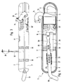
- a silencer arrangement comprises one Silencer 1 in multi-chamber design, which in a passenger car the micro class with a 3-cylinder rear engine is provided, the exhaust gas outlet to an exhaust gas turbocharger and its outlet with short piping to the illustrated one Muffler arrangement is connected.
- the Muffler arrangement is transverse to the vehicle and extends practically horizontally across the entire width of the small motor vehicle.
- the housing 4 of the silencer 1 is elongated and has Practically the same oval over its entire length Basic cross section. It consists of an upper half shell 2 and a lower half-shell 3, which are sheet metal parts. The two half-shells 2, 3 are through a fold 36 Form-fit gas-tight connection.
- the half-shell housing 4 there is a housing-free catalyst module 5 added, in particular form-fitting and in principle axially displaceable along the monolith circumference of the catalyst module 5, wherein the monolith for storage is a peripheral insulation 15 has.
- the catalyst module 5 is in the assembled state axially fixed in the housing, namely through its inlet funnel 11, which is an oblique flow of the monolith and therefore an optimal flow distribution in the catalyst allowed.
- the oblique does not extend circumferentially insulated inlet funnel 11 through a form-fitting jacket opening 13 in the half-shell housing 4.
- the funnel is on the Jacket opening 13 welded gas-tight.
- the funnel 11 goes short on the outside of the silencer curved connecting pipe piece 14, the free end with a ball flange 34 is provided.
- the ball flange has Cap screws 35 for connecting the muffler arrangement to an exhaust gas turbocharger.
- the catalyst module 5 faces the inlet funnel 13 opposite side an open, i.e. funnelless outflow side 12, so that a low exhaust back pressure during operation given is.
- the aforementioned arrangement of the catalyst module 5 in the half-shell housing 4 of the silencer arrangement is made so that the catalyst module 5 a silencer system partition forms and the half-shell housing 4 in a according to Figure 1 to the left of the catalytic converter main chamber and into one the other side of the additional chamber 9 divided, wherein the chambers via at least one in the half-shell housing 4 molded connection channel 10 are connected to each other, as can be seen in particular from FIG. 2.
- the additional chamber 9 is an empty space for increasing the volume and as such a resonator chamber or a Helmholtz resonator, which communicates with the main chamber.
- the catalyst module 5 is arranged so that its open Outflow side 12 points towards the main chamber.
- the main chamber with a cross section is according to the drawing as a 3-chamber pot (i.e. the one combined with the catalyst Muffler arrangement together with the Helmholtz additional chamber as a 4-chamber pot) and as such by two Intermediate floors 16, 17 in three individual chambers 6, 7, 8 divided, in the axial or longitudinal direction the main chamber, the first single chamber 6 between the Catalyst module 5 and the first intermediate floor 16, the second Single chamber 7 between the first intermediate floor 16 and the second intermediate floor 17 and the third individual chamber 8 between the second intermediate floor 17 and that according to the figures 1, 3 and 4 left end 18 of the half-shell housing 4 extends.
- a 3-chamber pot i.e. the one combined with the catalyst Muffler arrangement together with the Helmholtz additional chamber as a 4-chamber pot
- the first single chamber 6 is connected to an exhaust pipe inside the silencer 19 connected, which is straight inside the silencer is formed and axially according to Figure 1 the second single chamber 7, the third single chamber 4 and from there by the assigned end 18 of the half-shell housing 4 extends outwards and outside as Tail pipe of the exhaust system is curved.
- the outlet pipe 19 has in the region of the second single chamber 7 first jacket-side through openings 20 and in the area the third single chamber 8 second jacket-side through openings 21, wherein according to the embodiment of the Figures 1 to 3, the second jacket-side through openings 21 provided on the outside with circumferential insulation 23 are.
- the third single chamber 8 is outside of the total Outlet pipe 19 filled with a sound absorbing substance 24, i.e. it is the third single chamber 8 as an absorption chamber educated.
- the first jacket-side round through openings 20 have a larger diameter than the second jacket side round through openings 21.
- the space between half-shell housing 4 and outlet pipe 19 in The area of the second individual chamber 7 is an empty space.
- the second single chamber 7 is therefore designed as a reflection chamber.
- the end inflow opening of the outlet pipe 19 runs flush with the first intermediate floor 16 and has one central, tapered inlet throttle 25.
- the first intermediate floor 16 according to FIG. 1 is perforated.
- the half-shell housing has a structure to reduce structure-borne noise 4 stabilization indentations 30, which is preferred practically over the entire circumference parallel to the intermediate floors run.
- Local stabilization indentations 31, 30 are also present, especially in places where the outside of the jacket is different Find construction parts, e.g. a coat close Axle bearing of a motor vehicle.
- the local stability indentations 31 are in the area the second single chamber 7, while the local stabilization indentations 30 'in the area of the first single chamber 6 are provided and preferably in the connecting channel 10 or overflow channel to the additional chamber 9.
- a 4-chamber pot is also used an absorption chamber (third single chamber 8), two reflection chambers (first and second individual chambers 6, 7) and one Resonator chamber (additional chamber 9) created, a housingless Catalyst module 5 integrated in shape between the additional chamber 9 and the first single chamber 6 arranged as a partition is.
- the catalyst module is in the range the flow inlet of the silencer arrangement. In the the catalytic converter module are exhaust gases from the engine still comparatively hot.
- Figure 4 corresponds in principle that of Figures 1 to 3. However, the third is Single chamber 8 as a combined absorption / reflection chamber educated.
- the outlet pipe 19 is in the region of the second jacket-side through openings 21 with an absorption package equipped, which covers the through openings 21.
- the absorption package consists of an outlet pipe perforated overtube concentrically enclosing at a distance 26 and an embedded peripheral insulation 27.
- the first single chamber 6 is combined with the third combined absorption / reflection single chamber 8 via a silencer interior axially parallel additional pipe 28 ("bypass") connected, which extends through the second single chamber 7.
- the outlet pipe 19, which with respect to the longitudinal axis of the Muffler arrangement is arranged obliquely, points in Area of the second individual chamber 7 a cross-sectional taper 29 with steady transitions.
- the first and second through openings on the jacket side 20, 21 are designed as elongated holes.
- Former Openings 20 run on both sides of the aforementioned cross-sectional taper 29, based on the axial extent of the Silencer.
- Additional pipe 28 and outlet pipe 19 protrude with a short pipe length into the first single chamber 6.
Landscapes
- Engineering & Computer Science (AREA)
- Chemical & Material Sciences (AREA)
- Chemical Kinetics & Catalysis (AREA)
- Combustion & Propulsion (AREA)
- Mechanical Engineering (AREA)
- General Engineering & Computer Science (AREA)
- Health & Medical Sciences (AREA)
- Toxicology (AREA)
- Exhaust Silencers (AREA)
- Exhaust Gas After Treatment (AREA)
Description
- Der Katalysator/Schalldämpfer ist in einer einzigen Baueinheit direkt nach einem Abgasturbolader mit minimaler Vorrohrlänge vorgesehen.
- Das Katalysatormodul mit variabler Monolithlänge ist als eigenständige Fertigungseinheit im Schalldämpfer-Halbschalengehäuse integriert, verbunden entweder durch Schweißung oder durch Formschluß.
- Der in der Schalldämpferschale eingesetzte Katalysatorkörper teilt das Schalldämpfervolumen in eine Resonator-bzw. Helmholtzkammer und eine Hauptkammer und übernimmt so die Zusatzfunktion als Systemtrennboden.
- Das Katalysatormodul hat eine einseitig offene Ausströmung in das Schalldämpfergehäuse, wobei der nachfolgende Schalldämpferfunktionsaufbau in Reflexions-/Absorptions-Bauweise ausgebildet ist.
- Die Resonatorkammer und die Hauptkammer sind durch einen oder mehrere in das Halbschalengehäuse eingeformten Überströmkanal miteinander verkoppelt.
- Die Schalldämpfer-Hauptkammer ist als 3-Kammer-Reflexions-/Absorptions-System mit integrierter Ausgangsbrause und einer Überströmdrossel im Zwischenboden ausgebildet.
- Die Schalldämpfer-Hauptkammer ist alternativ als 3-Kammer-Reflexionssystem mit am Ausgangsrohr aufgesetztem Absorptionspaket und einer Überströmdrossel und zusätzlichem Bypassrohr ausgebildet.
- Das Absorptionspaket ist über ein perforiertes Überrohr zusätzlich an die dritte Einzelkammer bzw. Endkammer ange koppelt.
- Durch die Anordnung des Katalysatormoduls im Schalldämpfergehäuse und eine optimale Strömungsverteilung infolge der Schräganströmung werden eine sehr kurze Anspringzeit des Katalysators und eine gute Langzeitstabilität der Katalysatorbeschichtung erreicht.
- Durch die offene Katalysator-Ausströmung in das Schalldämpfergehäuse ergibt sich ein geringer Abgasgegendruck und damit ein minimaler Leistungsverlust des Motors, insbesondere bei Vorhandensein eines Abgasturboladers.
- Durch die Integration des kompletten Katalysatormoduls in das Schalldämpfergehäuse wird die Körperschallabstrahlung wesentlich verringert. Außerdem kann auf die Isolation des Katalysator-Eingangstrichters verzichtet werden.
- Durch die Unterteilung des Systems in verschiedene Fertigungsmodule (Katalysator/Schalldämpfer-Innenaufbau/Gehäuse) ist eine rationelle und kostensparende Fertigung möglich.
- Wesentliche Gewichtseinsparung durch die Kombination der einzelnen Fertigungsmodule in Multifunkton zu einer Funktionseinheit.
- Fig. 1
- eine Schalldämpfer-Anordnung mit integriertem Katalysatormodul schematisch in einem horizontalen Längsschnitt,
- Fig. 2
- einen schematischen Querschnitt durch die Schalldämpfer-Anordnung nach Fig. 1 längs der Linie A-A,
- Fig. 3
- die Schalldämpfer-Anordnung nach Fig. 1 in einer Seitenansicht, und
- Fig. 4
- eine Schalldämpfer-Anordnung ähnlich Fig. 1 in anderer Ausführungsvariante.
Claims (29)
- Schalldämpfer-Anordnung mit Schalldämpfer (1) in Mehrkammerbauweise, insbesondere für Personenkraftfahrzeuge, mit einem aus zwei Halbschalen (2, 3) zusammengesetzten Gehäuse (4), in welchem ein Katalysatormodul (5) integriert aufgenommen ist,
dadurch gekennzeichnet,
daß das mit einer einseitig offenen Ausströmungsseite in das Schalldämpfergehäuse versehene Katalysatormodul (5) einen Schalldämpfer-Systemtrennboden bildet und das Halbschalengehäuse (4) in eine Hauptkammer (6, 7, 8) und eine Zusatzkammer (9) in Form einer Resonatorkammer bzw. eines Helmholtz-Resonators unterteilt, wobei die Kammern über zumindest einen in das Halbschalengehäuse (4) eingeformten Verbindungskanal (10) miteinander verbunden sind. - Schalldämpfer-Anordnung nach Anspruch 1,
dadurch gekennzeichnet,
daß das Katalysatormodul (5) im Halbschalengehäuse (4) durch Formschluß und/oder durch Verschweißung befestigt ist. - Schalldämpfer-Anordnung nach Anspruch 1 oder 2,
dadurch gekennzeichnet,
daß der Querschnitt des Halbschalengehäuses (4) längs des Katalysatormoduls (5) im wesentlichen gleich ist, wobei im Querschnitt gleiche Katalysatormodule mit unterschiedlicher Monolithlänge in das Halbschalengehäuse (4) formschlüssig einsetzbar sind. - Schalldämpfer-Anordnung nach einem der Ansprüche 1 bis 3,
dadurch gekennzeichnet,
daß das Katalysatormodul (5) auf der Seite der Zusatzkammer (9) einen schrägen Einlaßtrichter (11) und auf der Seite der Hauptkammer (6, 7, 8) eine offene, d.h. trichterlose Auslaßströmungsseite (12) aufweist. - Schalldämpfer-Anordnung nach Anspruch 4,
dadurch gekennzeichnet,
daß der schräge Einlaßtrichter (11) sich durch eine Mantelöffnung (13) des Halbschalengehäuses (4) erstreckt und in dieser Mantelöffnung (13) abdichtend fixiert ist. - Schalldämpfer-Anordnung nach Anspruch 5,
dadurch gekennzeichnet,
daß der schräge Einlaßtrichter (11) ein kurzes vorzugsweise gekrümmtes Anschlußrohrstück (14) aufweist, welches mit einem Abgasturbolader oder direkt mit einem Motor, insbesondere Heckmotor, verbunden werden kann. - Schalldämpfer-Anordnung nach einem der Ansprüche 4 bis 6,
dadurch gekennzeichnet,
daß der Monolithmantel des Katalysatormoduls (5) für eine Lagerung im Halbschalengehäuse (4) eine Umfangsisolation (15) aufweist, während der schräge Einlaßtrichter (11) ohne zusätzliche Isolationsschicht ausgebildet ist. - Schalldämpfer-Anordnung nach einem der Ansprüche 1 bis 7,
dadurch gekennzeichnet,
daß die langgestreckte, im wesentlichen den gleichen Querschnitt aufweisende Hauptkammer durch zwei voneinander beabstandete Zwischenböden (16, 17) in drei Einzelkammern (6, 7, 8) unterteilt ist, wobei in Axial-bzw. Längsrichtung der Hauptkammer die erste Einzelkammer (6) zwischen dem Katalysatormodul (5) und dem ersten Zwischenboden (16), die zweite Einzelkammer (7) zwischen dem ersten Zwischenboden (16) und dem zweiten Zwischenboden (17) und die dritte Einzelkammer (8) zwischen dem zweiten Zwischenboden (17) und einem stirnseitigen Ende (18) des Halbschalengehäuses (4) sich erstreckt. - Schalldämpfer-Anordnung nach Anspruch 8,
dadurch gekennzeichnet,
daß die erste Einzelkammer (6) an ein schalldämpferinneres Auslaßrohr (19) angeschlossen ist, welches sich durch die zweite Einzelkammer (7), die dritte Einzelkammer (8) und das zugeordnete stirnseitige Ende (18) des Halbschalengehäuses (4) nach außen erstreckt. - Schalldämpfer-Anordnung nach Anspruch 9,
dadurch gekennzeichnet,
daß sich das Auslaßrohr (19) im Innern des Halbschalengehäuses (4) im wesentlichen parallel zur Längsachse des Halbschalengehäuses erstreckt. - Schalldämpfer-Anordnung nach Anspruch 9,
dadurch gekennzeichnet,
daß sich das Auslaßrohr (19) im Innern des Halbschalengehäuses (4) unter einem Neigungswinkel zur Längsachse des Halbschalengehäuses erstreckt. - Schalldämpfer-Anordnung nach einem der Ansprüche 9 bis 11,
dadurch gekennzeichnet,
daß das Auslaßrohr (19) im Bereich der zweiten Einzelkammer (7) erste mantelseitige Durchgangsöffnungen (20) und im Bereich der dritten Einzelkammer (8) zweite mantelseitige Durchgangsöffnungen (21) aufweist. - Schalldämpfer-Anordnung nach Anspruch 12,
dadurch gekennzeichnet,
daß die zweiten mantelseitigen Durchgangsöffnungen (21) außenseitig mit einer Umfangsisolation (23) versehen sind. - Schalldämpfer-Anordnung nach einem der Ansprüche 1 bis 13,
dadurch gekennzeichnet,
daß die erste und die zweite Einzelkammer (6, 7) als Reflexionskammern ausgebildet sind. - Schalldämpfer-Anordnung nach einem der Ansprüche 9 bis 14,
dadurch gekennzeichnet,
daß die dritte Einzelkammer (8) als Absorptionskammer ausgebildet und außerhalb des Auslaßrohrs (19) mit einem Schallschluckstoff (24) ausgefüllt ist. - Schalldämpfer-Anordnung nach Anspruch 15,
dadurch gekennzeichnet,
daß die zweite Einzelkammer (7) eine größere Längserstreckung als die dritte Einzelkammer (8) aufweist. - Schalldämpfer-Anordnung nach Anspruch 15 oder 16,
dadurch gekennzeichnet,
daß die ersten mantelseitigen Durchgangsöffnungen (20) einen größeren Durchmesser als die zweiten mantelseitigen Durchgangsöffnungen (21) besitzen. - Schalldämpfer-Anordnung nach einem der Ansprüche 15 bis 17,
dadurch gekennzeichnet,
daß die ersten und zweiten mantelseitigen Durchgangsöffnungen (20, 21) rund ausgebildet sind. - Schalldämpfer-Anordnung nach einem der Ansprüche 15 bis 18,
dadurch gekennzeichnet,
daß die stirnseitige Einströmöffnung des Auslaßrohrs (19) im Bereich des ersten Zwischenbodens (16) liegt. - Schalldämpfer-Anordnung nach einem der Ansprüche 15 bis 19,
dadurch gekennzeichnet,
daß die stirnseitige Einströmöffnung des Ausgangsrohrs (19) eine sich verjüngende Einströmdrossel (25) aufweist. - Schalldämpfer-Anordnung nach einem der Ansprüche 15 bis 20,
dadurch gekennzeichnet,
daß der erste Zwischenboden (16) perforiert ausgebildet ist. - Schalldämpfer-Anordnung nach einem der Ansprüche 1 bis 14,
dadurch gekennzeichnet,
daß die dritte Einzelkammer (8) als Reflexionskammer ausgebildet ist. - Schalldämpfer-Anordnung nach Anspruch 22,
dadurch gekennzeichnet,
daß die dritte Einzelkammer (8) im Außenumfangsbereich der zweiten mantelseitigen Durchgangsöffnungen (21) ein Absorptionspaket mit einem koaxial zum Ausgangsrohr (19) verlaufenden, beabstandeten Überrohr (26) aufweist, wobei zwischen Überrohr (26) und Ausgangsrohr (19) eine Umfangsisolierung (27) vorgesehen ist. - Schalldämpfer-Anordnung nach Anspruch 23,
dadurch gekennzeichnet,
daß das Überrohr (26) Perforationen aufweist. - Schalldämpfer-Anordnung nach einem der Ansprüche 22 bis 24,
dadurch gekennzeichnet,
daß die erste Einzelkammer (6) mit der dritten Einzelkammer (8) über ein schalldämpferinneres Zusatzrohr (28) verbunden ist, welches sich durch die zweite Einzelkammer (7) erstreckt. - Schalldämpfer-Anordnung nach einem der Ansprüche 22 bis 25,
dadurch gekennzeichnet,
daß das Auslaßrohr (19) im Bereich der zweiten Einzelkammer (7) eine Querschnittsverjüngung (29) mit stetigen Übergängen aufweist. - Schalldämpfer-Anordnung nach einem der Ansprüche 22 bis 26,
dadurch gekennzeichnet,
daß die ersten und zweiten mantelseitigen Durchgangsöffnungen (20, 21) Langlochbohrungen sind. - Schalldämpfer-Anordnung nach einem der Ansprüche 1 bis 27,
dadurch gekennzeichnet,
daß das Halbschalengehäuse (4) Stabilisierungseinbuchtungen (30, 31) aufweist. - Schalldämpfer-Anordnung nach einem der Ansprüche 1 bis 28,
dadurch gekennzeichnet,
daß sich das Halbschalengehäuse (4) im fahrzeugmontierten Zustand quererstreckt.
Applications Claiming Priority (3)
| Application Number | Priority Date | Filing Date | Title |
|---|---|---|---|
| DE19611133A DE19611133A1 (de) | 1996-03-21 | 1996-03-21 | Schalldämpfer-Anordnung |
| DE19611133 | 1996-03-21 | ||
| PCT/EP1997/001341 WO1997035100A1 (de) | 1996-03-21 | 1997-03-18 | Schalldämpfer-anordnung |
Publications (2)
| Publication Number | Publication Date |
|---|---|
| EP0888493A1 EP0888493A1 (de) | 1999-01-07 |
| EP0888493B1 true EP0888493B1 (de) | 2000-03-29 |
Family
ID=7788965
Family Applications (1)
| Application Number | Title | Priority Date | Filing Date |
|---|---|---|---|
| EP97908253A Expired - Lifetime EP0888493B1 (de) | 1996-03-21 | 1997-03-18 | Schalldämpfer-anordnung |
Country Status (6)
| Country | Link |
|---|---|
| US (1) | US6158214A (de) |
| EP (1) | EP0888493B1 (de) |
| JP (1) | JP3534777B2 (de) |
| DE (2) | DE19611133A1 (de) |
| ES (1) | ES2145583T3 (de) |
| WO (1) | WO1997035100A1 (de) |
Families Citing this family (51)
| Publication number | Priority date | Publication date | Assignee | Title |
|---|---|---|---|---|
| TW384349B (en) * | 1998-01-14 | 2000-03-11 | Emitec Emissionstechnologie | Catalytic converter for a muffler of a small engine |
| AU1870901A (en) * | 1999-12-09 | 2001-06-18 | Eminox Limited | Apparatus |
| AU144357S (en) | 2000-06-01 | 2001-07-05 | Hyundai Motor Co Ltd | Muffler for automobile |
| AU144358S (en) | 2000-06-01 | 2001-07-05 | Hyundai Motor Co Ltd | Muffler for automobile |
| AU144354S (en) | 2000-06-01 | 2001-07-05 | Hyundai Motor Co Ltd | Muffler for automobile |
| KR100378803B1 (ko) * | 2000-06-12 | 2003-04-07 | 엘지전자 주식회사 | 압축기용 소음기 |
| DE10042542A1 (de) * | 2000-08-30 | 2002-03-14 | Eberspaecher J Gmbh & Co | Abgasreinigungssystem für Kraftfahrzeuge, insbesondere Diesel-Nutzfahrzeuge |
| DE10128225C1 (de) * | 2001-06-11 | 2002-12-05 | Danfoss Compressors Gmbh | Saugschalldämpfer |
| JP2004132320A (ja) * | 2002-10-11 | 2004-04-30 | Toyota Motor Corp | 排気管構造 |
| US20040099475A1 (en) * | 2002-11-21 | 2004-05-27 | Francis Schulte | Muffling device and method for internal combustion engine |
| EP1510667B1 (de) * | 2003-08-26 | 2008-10-08 | ABB Turbo Systems AG | Schalldämpfer |
| US7273129B2 (en) * | 2003-09-05 | 2007-09-25 | Faurecia Exhaust Systems, Inc. | Muffler with internal heat shield |
| US20050150718A1 (en) * | 2004-01-09 | 2005-07-14 | Knight Jessie A. | Resonator with retention ribs |
| USD531093S1 (en) * | 2005-02-08 | 2006-10-31 | Kawasaki Jukogyo Kabushiki Kaisha | Cover for a motorcycle exhaust silencer |
| WO2007016767A1 (en) * | 2005-08-05 | 2007-02-15 | Rowe Grant M | Variable sound muffler system |
| US7870930B2 (en) * | 2005-09-02 | 2011-01-18 | Emcon Technologies Llc | Exhaust system with external helmholtz resonator and associated method |
| US20070290510A1 (en) * | 2006-06-16 | 2007-12-20 | Aratari Robert | Combustion Generator Enhancement Device |
| DE102009035738A1 (de) * | 2009-08-01 | 2011-02-03 | J. Eberspächer GmbH & Co. KG | Fahrzeugschalldämpfer |
| AT510788B1 (de) * | 2010-10-28 | 2012-10-15 | Avl List Gmbh | Abgasschalldämpferanordnung |
| DE102010062049A1 (de) * | 2010-11-26 | 2012-05-31 | J. Eberspächer GmbH & Co. KG | Schalldämpfer |
| US8609030B2 (en) | 2011-03-04 | 2013-12-17 | Tenneco Automotive Operating Company Inc. | Exhaust aftertreatment device with integrated shell and baffle |
| US8776509B2 (en) | 2011-03-09 | 2014-07-15 | Tenneco Automotive Operating Company Inc. | Tri-flow exhaust treatment device with reductant mixing tube |
| CN102606269B (zh) * | 2012-04-16 | 2013-11-06 | 陈尔斌 | 阻抗复合式消声器 |
| US8820475B2 (en) * | 2012-12-05 | 2014-09-02 | Caterpillar Inc. | Exhaust muffler |
| US9352276B2 (en) | 2013-05-07 | 2016-05-31 | Tenneco Automotive Operating Company Inc. | Exhaust mixing device |
| US9314750B2 (en) | 2013-05-07 | 2016-04-19 | Tenneco Automotive Operating Company Inc. | Axial flow atomization module |
| US9364790B2 (en) | 2013-05-07 | 2016-06-14 | Tenneco Automotive Operating Company Inc. | Exhaust mixing assembly |
| US9334781B2 (en) | 2013-05-07 | 2016-05-10 | Tenneco Automotive Operating Company Inc. | Vertical ultrasonic decomposition pipe |
| US9291081B2 (en) | 2013-05-07 | 2016-03-22 | Tenneco Automotive Operating Company Inc. | Axial flow atomization module |
| US9289724B2 (en) | 2013-05-07 | 2016-03-22 | Tenneco Automotive Operating Company Inc. | Flow reversing exhaust gas mixer |
| DE102014016448A1 (de) | 2014-11-06 | 2016-05-12 | Man Diesel & Turbo Se | Abgasnachbehandlungsvorrichtung und Verfahren zur Abgasnachbehandlung |
| US9534525B2 (en) | 2015-05-27 | 2017-01-03 | Tenneco Automotive Operating Company Inc. | Mixer assembly for exhaust aftertreatment system |
| WO2019194784A1 (en) | 2018-04-02 | 2019-10-10 | Cummins Emission Solutions Inc. | Aftertreatment system including noise reducing components |
| WO2020009694A1 (en) | 2018-07-03 | 2020-01-09 | Cummins Emission Solutions Inc. | Body mixing decomposition reactor |
| TWD201753S (zh) * | 2018-10-25 | 2020-01-01 | 伊戈爾 阿克拉波維奇 | 排氣管 |
| US11280258B2 (en) | 2018-12-07 | 2022-03-22 | Polaris Industries Inc. | Exhaust gas bypass valve system for a turbocharged engine |
| US20200182164A1 (en) | 2018-12-07 | 2020-06-11 | Polaris Industries Inc. | Method And System For Predicting Trapped Air Mass In A Two-Stroke Engine |
| US11174779B2 (en) | 2018-12-07 | 2021-11-16 | Polaris Industries Inc. | Turbocharger system for a two-stroke engine |
| US11236668B2 (en) | 2018-12-07 | 2022-02-01 | Polaris Industries Inc. | Method and system for controlling pressure in a tuned pipe of a two stroke engine |
| US11725573B2 (en) | 2018-12-07 | 2023-08-15 | Polaris Industries Inc. | Two-passage exhaust system for an engine |
| US11352935B2 (en) * | 2018-12-07 | 2022-06-07 | Polaris Industries Inc. | Exhaust system for a vehicle |
| US11639684B2 (en) | 2018-12-07 | 2023-05-02 | Polaris Industries Inc. | Exhaust gas bypass valve control for a turbocharger for a two-stroke engine |
| US11828239B2 (en) | 2018-12-07 | 2023-11-28 | Polaris Industries Inc. | Method and system for controlling a turbocharged two stroke engine based on boost error |
| TWD208036S (zh) * | 2019-10-30 | 2020-11-01 | 伊戈爾 阿克拉波維奇 | 摩托車排氣管 |
| TWD208035S (zh) * | 2019-10-30 | 2020-11-01 | 伊戈爾 阿克拉波維奇 | 摩托車排氣管 |
| CA3201948A1 (en) | 2020-01-13 | 2021-07-13 | Polaris Industries Inc. | Turbocharger system for a two-stroke engine having selectable boost modes |
| CA3298986A1 (en) | 2020-01-13 | 2026-03-02 | Polaris Industries Inc. | Turbocharger lubrication system for a two-stroke engine |
| US11788432B2 (en) | 2020-01-13 | 2023-10-17 | Polaris Industries Inc. | Turbocharger lubrication system for a two-stroke engine |
| US11434834B2 (en) | 2020-01-13 | 2022-09-06 | Polaris Industries Inc. | Turbocharger system for a two-stroke engine having selectable boost modes |
| DE102021115392A1 (de) * | 2021-06-15 | 2022-12-15 | Purem GmbH | Schalldämpfer für eine Abgasanlage einer Brennkraftmaschine |
| DE102021119216A1 (de) * | 2021-07-26 | 2023-01-26 | Purem GmbH | Schalldämpfer |
Family Cites Families (11)
| Publication number | Priority date | Publication date | Assignee | Title |
|---|---|---|---|---|
| JPS582410A (ja) * | 1981-06-26 | 1983-01-08 | Nissan Motor Co Ltd | 消音器 |
| JPS60184919A (ja) * | 1984-03-01 | 1985-09-20 | Nissan Motor Co Ltd | 内燃機関用触媒マフラ−装置 |
| US4894987A (en) * | 1988-08-19 | 1990-01-23 | Ap Parts Manufacturing Company | Stamp formed muffler and catalytic converter assembly |
| EP0556846A1 (de) * | 1992-02-19 | 1993-08-25 | LEISTRITZ AG & CO. Abgastechnik | Abgasschalldämpfer für Dieselmotoren insbesondere von Nutzfahrzeugen |
| JP3200772B2 (ja) * | 1992-03-30 | 2001-08-20 | ヤマハ発動機株式会社 | 内燃機関用触媒付きマフラー |
| US5426269A (en) * | 1992-06-02 | 1995-06-20 | Donaldson Company, Inc. | Muffler with catalytic converter arrangement; and method |
| JPH05340234A (ja) * | 1992-06-05 | 1993-12-21 | Kubota Corp | エンジンの排気浄化消音装置 |
| US5376341A (en) * | 1992-07-24 | 1994-12-27 | Corning Incorporated | Catalytic converter for motorcycles |
| DE4244613C2 (de) * | 1992-12-31 | 1995-12-21 | Eberspaecher J | Abgasbehandlungsvorrichtung für Abgasanlagen von Kraftfahrzeugen |
| JP3304508B2 (ja) * | 1993-05-28 | 2002-07-22 | スズキ株式会社 | 自動二輪車の排気浄化装置 |
| DE4427459A1 (de) * | 1994-08-03 | 1996-02-08 | Roth Technik Gmbh | Abgasanlage |
-
1996
- 1996-03-21 DE DE19611133A patent/DE19611133A1/de not_active Withdrawn
-
1997
- 1997-03-18 US US09/142,969 patent/US6158214A/en not_active Expired - Fee Related
- 1997-03-18 ES ES97908253T patent/ES2145583T3/es not_active Expired - Lifetime
- 1997-03-18 JP JP53314297A patent/JP3534777B2/ja not_active Expired - Fee Related
- 1997-03-18 WO PCT/EP1997/001341 patent/WO1997035100A1/de not_active Ceased
- 1997-03-18 EP EP97908253A patent/EP0888493B1/de not_active Expired - Lifetime
- 1997-03-18 DE DE59701361T patent/DE59701361D1/de not_active Expired - Fee Related
Also Published As
| Publication number | Publication date |
|---|---|
| US6158214A (en) | 2000-12-12 |
| ES2145583T3 (es) | 2000-07-01 |
| JP2000503743A (ja) | 2000-03-28 |
| EP0888493A1 (de) | 1999-01-07 |
| JP3534777B2 (ja) | 2004-06-07 |
| DE19611133A1 (de) | 1997-09-25 |
| WO1997035100A1 (de) | 1997-09-25 |
| DE59701361D1 (de) | 2000-05-04 |
Similar Documents
| Publication | Publication Date | Title |
|---|---|---|
| EP0888493B1 (de) | Schalldämpfer-anordnung | |
| DE69105882T2 (de) | Schalldämpfer für Motoren. | |
| EP0807749B1 (de) | Abgasanlage für ein Kraftfahrzeug sowie Kraftfahrzeug | |
| DE60122688T2 (de) | Schalldämpfer mit einem oder mehreren porösen körpern | |
| DE102005037102B4 (de) | An einem Katalysator angebrachter Auspufftopf für einen Verbrennungsmotor | |
| EP3623593B1 (de) | Schalldämpfer für einen abgasstrang eines kraftfahrzeugs und kraftfahrzeug mit einem schalldämpfer | |
| EP1475522A2 (de) | Kombinierte Abgasnachbehandlungs-/Schalldämpfungsvorrichtung im Abgasstrang einer Brennkraftmaschine | |
| WO1999036681A1 (de) | Katalytischer konverter für einen schalldämpfer eines kleinmotors | |
| EP0931913B1 (de) | Abgasschalldämpfer für Verbrennungsmotoren | |
| EP2314834B1 (de) | Abgasanlage mit Y-Verteiler | |
| EP0816648B1 (de) | Schalldämpfer für Kraftfahrzeuge | |
| EP3061931B1 (de) | Abgasführungssystem für eine brennkraftmaschine | |
| DE2537946C2 (de) | Auspuffanlage | |
| DE69907912T2 (de) | Schalldämpfer mit katalytischer Vorrichtung für Zweitakt-Brennkraftmaschinen und katalytische Vorrichtung hierfür | |
| DE7307335U (de) | Abgasschalldaempfer fuer zweitakt- motore | |
| DE2930775C2 (de) | Absorptionsschalldämpfer für Abgase | |
| EP1795719A1 (de) | Schalldämpfer für eine Abgasanlage | |
| DE60214748T2 (de) | In einem abgassystem für einen verbrennungsmotor angeordnetes gehäuse | |
| DE102019105691A1 (de) | Verfahren zum bereitstellen eines leckfreien akustischen volumens für ein fahrzeugrahmenelement | |
| DE3439208C1 (de) | Abgasschalldämpfer für Brennkraftmaschinen | |
| EP1541823B1 (de) | Schalldämpfer für eine Abgasanlage | |
| DE19706883A1 (de) | Abgas-Schalldämpfer für Kraftfahrzeuge mit Verbrennungsmotoren | |
| EP3759327B1 (de) | Vorrichtung zur abgasnachbehandlung | |
| EP4379196A1 (de) | Schalldämpfer für eine abgasanlage | |
| DE102018115351A1 (de) | Abluftvorrichtung |
Legal Events
| Date | Code | Title | Description |
|---|---|---|---|
| PUAI | Public reference made under article 153(3) epc to a published international application that has entered the european phase |
Free format text: ORIGINAL CODE: 0009012 |
|
| 17P | Request for examination filed |
Effective date: 19980826 |
|
| AK | Designated contracting states |
Kind code of ref document: A1 Designated state(s): DE ES FR GB IT |
|
| 17Q | First examination report despatched |
Effective date: 19990125 |
|
| GRAG | Despatch of communication of intention to grant |
Free format text: ORIGINAL CODE: EPIDOS AGRA |
|
| GRAG | Despatch of communication of intention to grant |
Free format text: ORIGINAL CODE: EPIDOS AGRA |
|
| GRAH | Despatch of communication of intention to grant a patent |
Free format text: ORIGINAL CODE: EPIDOS IGRA |
|
| GRAH | Despatch of communication of intention to grant a patent |
Free format text: ORIGINAL CODE: EPIDOS IGRA |
|
| GRAA | (expected) grant |
Free format text: ORIGINAL CODE: 0009210 |
|
| ITF | It: translation for a ep patent filed | ||
| AK | Designated contracting states |
Kind code of ref document: B1 Designated state(s): DE ES FR GB IT |
|
| ET | Fr: translation filed | ||
| GBT | Gb: translation of ep patent filed (gb section 77(6)(a)/1977) |
Effective date: 20000329 |
|
| REF | Corresponds to: |
Ref document number: 59701361 Country of ref document: DE Date of ref document: 20000504 |
|
| RAP2 | Party data changed (patent owner data changed or rights of a patent transferred) |
Owner name: MICRO COMPACT CAR SMART GMBH Owner name: J. EBERSPAECHER GMBH & CO. |
|
| REG | Reference to a national code |
Ref country code: ES Ref legal event code: FG2A Ref document number: 2145583 Country of ref document: ES Kind code of ref document: T3 |
|
| REG | Reference to a national code |
Ref country code: GB Ref legal event code: 732E |
|
| PLBE | No opposition filed within time limit |
Free format text: ORIGINAL CODE: 0009261 |
|
| STAA | Information on the status of an ep patent application or granted ep patent |
Free format text: STATUS: NO OPPOSITION FILED WITHIN TIME LIMIT |
|
| 26N | No opposition filed | ||
| REG | Reference to a national code |
Ref country code: GB Ref legal event code: IF02 |
|
| REG | Reference to a national code |
Ref country code: ES Ref legal event code: PC2A |
|
| REG | Reference to a national code |
Ref country code: FR Ref legal event code: CJ |
|
| REG | Reference to a national code |
Ref country code: FR Ref legal event code: CJ |
|
| PGFP | Annual fee paid to national office [announced via postgrant information from national office to epo] |
Ref country code: GB Payment date: 20040317 Year of fee payment: 8 |
|
| PG25 | Lapsed in a contracting state [announced via postgrant information from national office to epo] |
Ref country code: GB Free format text: LAPSE BECAUSE OF NON-PAYMENT OF DUE FEES Effective date: 20050318 |
|
| GBPC | Gb: european patent ceased through non-payment of renewal fee |
Effective date: 20050318 |
|
| PGFP | Annual fee paid to national office [announced via postgrant information from national office to epo] |
Ref country code: ES Payment date: 20070215 Year of fee payment: 11 |
|
| PGFP | Annual fee paid to national office [announced via postgrant information from national office to epo] |
Ref country code: IT Payment date: 20070508 Year of fee payment: 11 |
|
| PGFP | Annual fee paid to national office [announced via postgrant information from national office to epo] |
Ref country code: FR Payment date: 20070215 Year of fee payment: 11 |
|
| REG | Reference to a national code |
Ref country code: FR Ref legal event code: ST Effective date: 20081125 |
|
| PG25 | Lapsed in a contracting state [announced via postgrant information from national office to epo] |
Ref country code: FR Free format text: LAPSE BECAUSE OF NON-PAYMENT OF DUE FEES Effective date: 20080331 |
|
| REG | Reference to a national code |
Ref country code: ES Ref legal event code: FD2A Effective date: 20080319 |
|
| PG25 | Lapsed in a contracting state [announced via postgrant information from national office to epo] |
Ref country code: ES Free format text: LAPSE BECAUSE OF NON-PAYMENT OF DUE FEES Effective date: 20080319 |
|
| PG25 | Lapsed in a contracting state [announced via postgrant information from national office to epo] |
Ref country code: IT Free format text: LAPSE BECAUSE OF NON-PAYMENT OF DUE FEES Effective date: 20080318 |
|
| PGFP | Annual fee paid to national office [announced via postgrant information from national office to epo] |
Ref country code: DE Payment date: 20090331 Year of fee payment: 13 |
|
| PG25 | Lapsed in a contracting state [announced via postgrant information from national office to epo] |
Ref country code: DE Free format text: LAPSE BECAUSE OF NON-PAYMENT OF DUE FEES Effective date: 20101001 |