EP0888511B1 - Pile connection sealing ring - Google Patents
Pile connection sealing ring Download PDFInfo
- Publication number
- EP0888511B1 EP0888511B1 EP97908252A EP97908252A EP0888511B1 EP 0888511 B1 EP0888511 B1 EP 0888511B1 EP 97908252 A EP97908252 A EP 97908252A EP 97908252 A EP97908252 A EP 97908252A EP 0888511 B1 EP0888511 B1 EP 0888511B1
- Authority
- EP
- European Patent Office
- Prior art keywords
- sealing ring
- protective strip
- sliding surface
- slide
- lubricant
- Prior art date
- Legal status (The legal status is an assumption and is not a legal conclusion. Google has not performed a legal analysis and makes no representation as to the accuracy of the status listed.)
- Expired - Lifetime
Links
- 238000007789 sealing Methods 0.000 title claims abstract description 35
- 230000001681 protective effect Effects 0.000 claims abstract description 44
- 239000000314 lubricant Substances 0.000 claims abstract description 27
- 239000000463 material Substances 0.000 claims abstract description 17
- 229920001971 elastomer Polymers 0.000 claims abstract description 7
- 239000000806 elastomer Substances 0.000 claims abstract description 7
- 239000002184 metal Substances 0.000 claims abstract description 5
- 229910052751 metal Inorganic materials 0.000 claims abstract description 5
- 239000004033 plastic Substances 0.000 claims abstract description 5
- 229920003023 plastic Polymers 0.000 claims abstract description 5
- 229910010293 ceramic material Inorganic materials 0.000 claims abstract description 4
- 230000002093 peripheral effect Effects 0.000 claims abstract description 4
- 239000011248 coating agent Substances 0.000 claims description 9
- 238000000576 coating method Methods 0.000 claims description 9
- VYPSYNLAJGMNEJ-UHFFFAOYSA-N silicon dioxide Inorganic materials O=[Si]=O VYPSYNLAJGMNEJ-UHFFFAOYSA-N 0.000 claims description 4
- OKTJSMMVPCPJKN-UHFFFAOYSA-N Carbon Chemical compound [C] OKTJSMMVPCPJKN-UHFFFAOYSA-N 0.000 claims description 3
- 239000010439 graphite Substances 0.000 claims description 3
- 229910002804 graphite Inorganic materials 0.000 claims description 3
- 239000010453 quartz Substances 0.000 claims description 3
- 239000000454 talc Substances 0.000 claims description 3
- 229910052623 talc Inorganic materials 0.000 claims description 3
- 244000144992 flock Species 0.000 claims 1
- 235000012054 meals Nutrition 0.000 claims 1
- 230000008878 coupling Effects 0.000 abstract 1
- 238000010168 coupling process Methods 0.000 abstract 1
- 238000005859 coupling reaction Methods 0.000 abstract 1
- 239000010410 layer Substances 0.000 description 13
- 239000007921 spray Substances 0.000 description 3
- 238000004873 anchoring Methods 0.000 description 2
- 235000013312 flour Nutrition 0.000 description 2
- 150000002739 metals Chemical class 0.000 description 2
- 239000006004 Quartz sand Substances 0.000 description 1
- 239000000654 additive Substances 0.000 description 1
- 239000000853 adhesive Substances 0.000 description 1
- 230000001070 adhesive effect Effects 0.000 description 1
- 239000004566 building material Substances 0.000 description 1
- 235000013339 cereals Nutrition 0.000 description 1
- 235000014113 dietary fatty acids Nutrition 0.000 description 1
- 239000000428 dust Substances 0.000 description 1
- 239000003925 fat Substances 0.000 description 1
- 239000000194 fatty acid Substances 0.000 description 1
- 229930195729 fatty acid Natural products 0.000 description 1
- 150000004665 fatty acids Chemical class 0.000 description 1
- 230000009969 flowable effect Effects 0.000 description 1
- 239000011859 microparticle Substances 0.000 description 1
- 239000000203 mixture Substances 0.000 description 1
- 239000004810 polytetrafluoroethylene Substances 0.000 description 1
- 229920001343 polytetrafluoroethylene Polymers 0.000 description 1
- 230000000284 resting effect Effects 0.000 description 1
- 239000012791 sliding layer Substances 0.000 description 1
- 229920003048 styrene butadiene rubber Polymers 0.000 description 1
- 239000013008 thixotropic agent Substances 0.000 description 1
- 238000004073 vulcanization Methods 0.000 description 1
Images
Classifications
-
- F—MECHANICAL ENGINEERING; LIGHTING; HEATING; WEAPONS; BLASTING
- F16—ENGINEERING ELEMENTS AND UNITS; GENERAL MEASURES FOR PRODUCING AND MAINTAINING EFFECTIVE FUNCTIONING OF MACHINES OR INSTALLATIONS; THERMAL INSULATION IN GENERAL
- F16L—PIPES; JOINTS OR FITTINGS FOR PIPES; SUPPORTS FOR PIPES, CABLES OR PROTECTIVE TUBING; MEANS FOR THERMAL INSULATION IN GENERAL
- F16L21/00—Joints with sleeve or socket
- F16L21/02—Joints with sleeve or socket with elastic sealing rings between pipe and sleeve or between pipe and socket, e.g. with rolling or other prefabricated profiled rings
- F16L21/035—Joints with sleeve or socket with elastic sealing rings between pipe and sleeve or between pipe and socket, e.g. with rolling or other prefabricated profiled rings placed around the spigot end before connection
-
- F—MECHANICAL ENGINEERING; LIGHTING; HEATING; WEAPONS; BLASTING
- F16—ENGINEERING ELEMENTS AND UNITS; GENERAL MEASURES FOR PRODUCING AND MAINTAINING EFFECTIVE FUNCTIONING OF MACHINES OR INSTALLATIONS; THERMAL INSULATION IN GENERAL
- F16L—PIPES; JOINTS OR FITTINGS FOR PIPES; SUPPORTS FOR PIPES, CABLES OR PROTECTIVE TUBING; MEANS FOR THERMAL INSULATION IN GENERAL
- F16L21/00—Joints with sleeve or socket
- F16L21/02—Joints with sleeve or socket with elastic sealing rings between pipe and sleeve or between pipe and socket, e.g. with rolling or other prefabricated profiled rings
- F16L21/03—Joints with sleeve or socket with elastic sealing rings between pipe and sleeve or between pipe and socket, e.g. with rolling or other prefabricated profiled rings placed in the socket before connection
Definitions
- the invention relates to a sealing ring made of an elastomer for a push-in joint to seal the gap between Ends of pipes made of hard material (concrete or other ceramic material, plastic, metal), with a Main torus made of an elastomer with a sliding surface, through which the pipe connection can be made self-centering is, with the main torus of the sealing ring in the Area of the sliding surface with at least one circumferential, easily removable protective strip connected to the Sliding surface initially covers and between its Underside and the sliding surface leaves a cavity, and the sliding surface with one below the protective strip lying lubricant layer is provided.
- a sealing ring of this type is known (US A 4,496,175). Disadvantageous in the known sealing ring is that when tearing of the protective strip, the lubricant partly with the protective strip is removed or the protective strip is torn off difficult, especially when it is at low temperatures has become stiff.
- This problem is solved by adding the sliding layer its side facing the inside of the protective strip is provided with an adhesion-reducing coating or the inside of the protective strip with an adhesion reducing Coating is provided.
- This coating can, for example, from quartz flour, talc, graphite, one Flocking or a fleece pad exist. It is also possible a siliconized layer on the inside of the Protective strip.
- the protective strip usually consists of a one-piece, thin, wing-like element. But it should also cannot be excluded, the protective strip from two to produce wing-like halves, each one-sided a peripheral outer edge of the sliding surface easily are removably attached in this case the lubricant layer through a nozzle with the protective strip open be introduced.
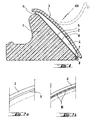
- the sealing ring 100 shown in Figure 1 consists of a Elastomer, especially styrene-butadiene rubber.
- the sealing ring 100 is used to seal the gap between two pipe ends of pipes made of hard material. He will be on top raised.
- the pipe materials include, for example Concrete, other ceramic materials, plastics or metals. In general, however, it should be indicated that sealing rings with corresponding dimensions also for shaft structures individual shaft rings, fittings and the like is suitable, without leaving the scope of the invention.
- Main torus 1 present, on an abutment at the tip end can be connected to the pipe. But it is not excluded that the sealing ring under tension in corresponding Grooves are inserted or by anchoring in the pipe material, preferably on the socket side becomes. It is also not excluded that the main torus 1 designed as a hollow profile or with different fillings is.
- the main torus 1 has a sliding surface 2 on which the End of a tube can be pushed on.
- the sliding surface is provided with a lubricant layer 5 which consists of a known lubricants from a mixture of saponified Metals, fats, fatty acids and inorganic additives.
- the lubricant layer 5 is covered by a protective strip 3 protected, which has been extruded together with the main torus 1 and is made of the same material.
- the protective strip 3 is over a thin material web 6 with the Main torus 1 connected.
- the material web 6 is designed that when the sealing ring is stretched, the on-hook of the sealing ring e.g. to the pointy end, going ahead, partial tears (at 16; see FIG. 2a, 2b) and thus tearing of the protective strip 3 facilitated by the main torus 1.
- the protective strip At its front end is the protective strip with a barb profile 7 provided that in a compatible groove 8 of the Main torus 1 engages or can be engaged.
- This resulting circumferential locking element enables easy removal of the protective strip 3 from the lower half of the main torus, so that it lies folded down, as dashed in Figure 1 shown.
- Limit the material web 6 and the locking element a cavity 4 which between the sliding surface 2 and the protective strip 3 is formed. It should be noted that instead of the material web 6 also on the upper Half a locking element can be provided with a lock element located on the main torus 1 can be locked different solutions are available to the person skilled in the art stand.
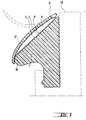
- Figure 3 shows a second embodiment of a sealing ring.
- a main torus 1 that rests on an abutment can be connected to the pipe at the tip end. It but do not rule out that the sealing ring is under tension is inserted in appropriate grooves or by anchoring in the pipe material, preferably on the socket side, is held.
- the main torus 1 has a sliding surface 2 on which the End of a tube can be pushed on.
- the sliding surface is provided with the lubricant layer 5.
- the lubricant layer 5 is covered by a protective strip 3 ' protected, which has been extruded together with the main torus 1 and is made of another, coextrudable material.
- the protective strip 3 ' is over a thin material web 6 connected to the main torus 1.
- the material web 6 is at the main torus at the tube tip end 18 facing Side attached.
- the protective strip 3 At its rear end, the protective strip 3 'ends like a lip resting on the main torus, he is there with this connected by a tearable adhesive 19.
- the Elements 6 and 19 allow the protective strip to be removed easily 3 'from the main torus.
- the protective strip can be applied before bonding can be folded down and is dashed as in Figure 3 shown.
- the cavity 4 between the sliding surface 2 and the protective strip 3 is formed with be filled with a lubricant.
- a locking element can also be provided on the upper half can, that with a located on the main torus 1 Counter element can be locked.
- the Inside of the protective strip with an adhesion reducing Coating 11, in particular with a siliconized Layer is provided.
- the fresh one Lubricant layer with an anti-adhesion coating to dust for example from quartz flour, talc or Graphite.
- quartz sand with a grain size can also be used 0.2 to 0.4 mm, as offered in the building materials trade will be dusted.
- flocking with plastic microparticles made of PTFE or with a fleece pad conceivable.
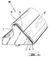
- FIG. 4 Such an adhesion-reducing coating is shown in FIG. 4 provided with the reference number 12.
- an embodiment can also be used be selected in which the protective strip consists of two wing-like halves 13, 13 ', each one-sided easily removable on an outer edge of the sliding surface 2 are attached.
- the lubricant can in this embodiment by means of a nozzle that goes into the central opening is retractable between the two wing-like halves, be pushed in.
Landscapes
- Engineering & Computer Science (AREA)
- General Engineering & Computer Science (AREA)
- Mechanical Engineering (AREA)
- Gasket Seals (AREA)
- Joints With Sleeves (AREA)
- Flanged Joints, Insulating Joints, And Other Joints (AREA)
- Non-Disconnectible Joints And Screw-Threaded Joints (AREA)
Abstract
Description
Die Erfindung betrifft einen Dichtring aus einem Elastomer für eine Steckmuffenverbindung zum Abdichten des Spaltes zwischen Enden von Rohren- aus hartem Material (Beton oder anderes keramisches Material, Kunststoff, Metall), mit einem Haupttorus aus einem Elastomer, der eine Aufgleitfläche besitzt, über die die Rohrverbindung selbstzentrierend herstellbar ist, wobei der Haupttorus des Dichtringes im Bereich der Aufgleitfläche mit wenigstens einem umlaufenden, leicht entfernbaren Schutzstreifen verbunden ist, der die Aufgleitfläche zunächst abdeckt und zwischen seiner Unterseite und der Aufgleitfläche einen Hohlraum beläßt, und wobei die Aufgleitfläche mit einer unterhalb des Schutzstreifens liegenden Gleitmittelschicht versehen ist.The invention relates to a sealing ring made of an elastomer for a push-in joint to seal the gap between Ends of pipes made of hard material (concrete or other ceramic material, plastic, metal), with a Main torus made of an elastomer with a sliding surface, through which the pipe connection can be made self-centering is, with the main torus of the sealing ring in the Area of the sliding surface with at least one circumferential, easily removable protective strip connected to the Sliding surface initially covers and between its Underside and the sliding surface leaves a cavity, and the sliding surface with one below the protective strip lying lubricant layer is provided.
Ein Dichtring dieser Art ist bekannt (US A 4 496 175). Nachteilig bei dem bekannten Dichtring ist, daß beim Abreißen des Schutzstreifens das Gleitmittel zum Teil mit dem Schutzstreifen entfernt wird oder das Abreißen des Schutzstreifens erschwert, insbesondere wenn es bei niedrigen Temperaturen steif geworden ist.A sealing ring of this type is known (US A 4,496,175). Disadvantageous in the known sealing ring is that when tearing of the protective strip, the lubricant partly with the protective strip is removed or the protective strip is torn off difficult, especially when it is at low temperatures has become stiff.
Weitere Dichtringe, bei denen die Aufgleitfläche mit einer unterhalb des Schutzstreifens liegenden Gleitmittelschicht versehen ist, sind aus der EP 0 691 498 A1 bekannt. Hier treten im wesentlichen dieselben Nachteile auf, wie bei dem Stand der Technik gemäß US A 4 496 175.Other sealing rings in which the sliding surface with a lubricant layer below the protective strip are known from EP 0 691 498 A1. Here there are essentially the same disadvantages as the State of the art according to US A 4,496,175.
Es stellt sich daher die Aufgabe, die vorgenannten Nachteile zu beseitigen und die Handhabung beim Abreißen des Schutzstreifens von der Gleitmittelschicht zu erleichtern.It is therefore the task of the aforementioned disadvantages to eliminate and handling when tearing off the protective strip from the lubricant layer.
Diese Aufgabe wird gelöst, indem die gleitende Schicht an ihrer der Innenseite des Schutzstreifens zugewandten Seite mit einer adhäsionsmindernden Beschichtung versehen ist oder die Innenseite des Schutzstreifens mit einer adhäsionsmindernden Beschichtung versehen ist. Diese Beschichtung kann beispielsweise aus Quarzmehl, Talkum, Graphit, einer Beflockung oder einer Vliesauflage bestehen. Es ist auch möglich, eine silikonisierte Schicht an der Innenseite des Schutzstreifens vorzusehen.This problem is solved by adding the sliding layer its side facing the inside of the protective strip is provided with an adhesion-reducing coating or the inside of the protective strip with an adhesion reducing Coating is provided. This coating can, for example, from quartz flour, talc, graphite, one Flocking or a fleece pad exist. It is also possible a siliconized layer on the inside of the Protective strip.
Üblicherweise besteht der Schutzstreifen aus einem einteiligen, dünnen, flügelartigen Element. Es soll aber auch nicht ausgeschlossen werden, den Schutzstreifen aus zwei flügelartigen Hälften herzustellen, die jeweils einseitig an einer peripheren Außenkante der Aufgleitfläche leicht entfernbar angebracht sind In diesem Fall kann die Gleitmittelschicht durch eine Düse bei aufgeklapptem Schutzstreifen eingebracht werden.The protective strip usually consists of a one-piece, thin, wing-like element. But it should also cannot be excluded, the protective strip from two to produce wing-like halves, each one-sided a peripheral outer edge of the sliding surface easily are removably attached in this case the lubricant layer through a nozzle with the protective strip open be introduced.
Ausführungbeispiele der Erfindung werden anhand der Zeichnung erläutert.Embodiments of the invention are shown in the drawing explained.
Die Figuren der Zeichnung zeigen im einzelnen:
Der in Figur 1 dargestellte Dichtring 100 besteht aus einem
Elastomer, insbesondere Styrol-Butadien-Kautschuk. Der Dichtring
100 dient zum Abdichten des Spaltes zwischen zwei Rohrenden
von Rohren aus hartem Material. Er wird auf das Spitzende
aufgezogen. Zu dem Rohrmaterialien zählen beispielsweise
Beton, andere keramische Materialien, Kunststoffe oder Metalle.
Allgemein sei aber angedeutet, daß sich Dichtringe
mit entsprechenden Abmessungen auch für Schachtaufbauten aus
einzelnen Schachtringen, Formstücke und dergleichen eignet,
ohne daß der Schutzumfang der Erfindung verlassen wird.The
Wie an sich bei derartigen Dichtringen bekannt, ist ein
Haupttorus 1 vorhanden, der auf einem Widerlager am Spitzende
mit dem Rohr verbunden werden kann. Es sei aber nicht ausgeschlossen,
daß der Dichtring unter Spannung in entsprechende
Nuten eingelegt wird oder durch Verankerung im Rohrwerkstoff,
vorzugsweise auf der Muffenseite, festgehalten
wird. Es sei auch nicht ausgeschlossen, daß der Haupttorus 1
als Hohlprofil oder mit verschiedenen Füllungen gestaltet
ist.As is known per se with such sealing rings, is a
Der Haupttorus 1 besitzt eine Aufgleitfläche 2, auf die das
Ende eines Rohres aufschiebbar ist. Die Aufgleitfläche ist
mit einer Gleitmittelschicht 5 versehen, die aus einem an
sich bekannten Gleitmittel aus einem Gemisch aus verseiften
Metallen, Fetten, Fettsäuren und anorganischen Additiven besteht. The
Die Gleitmittelschicht 5 wird durch einen Schutzstreifen 3
geschützt, der zusammen mit dem Haupttorus 1 extrudiert worden
ist und aus demselben Material besteht. Der Schutzstreifen
3 ist über einen dünnen Materialsteg 6 mit dem
Haupttorus 1 verbunden. Der Materialsteg 6 ist so beschaffen,
daß er bei Dehnung des Dichtringes, die dem Auflegen
des Dichtringes z.B. auf das Spitzende, vorangeht, partiell
einreißt (bei 16; vgl. Figur 2a, 2b) und somit das Abreißen
des Schutzstreifens 3 vom Haupttorus 1 erleichtert.The
An seinem vorderen Ende ist der Schutzstreifen mit einem Widerhakenprofil
7 versehen, das in eine kompatible Nut 8 des
Haupttorus 1 einrastet oder einrastbar ist. Dieses sich ergebende
umlaufende Rastelement ermöglicht ein einfaches Abziehen
des Schutzstreifens 3 von der unteren Hälfte des Haupttorus,
so daß es abgeklappt liegt, wie in Figur 1 gestrichelt
dargestellt. Der Materialsteg 6 und das Rastelement begrenzen
einen Hohlraum 4, der zwischen der Aufgleitfläche 2 und
dem Schutzstreifen 3 gebildet ist. Es sei darauf hingewiesen,
daß an Stelle des Materialsteges 6 auch an der oberen
Hälfte ein Rastelement vorgesehen werden kann, das mit einem
auf dem Haupttorus 1 befindlichen Konterelement verrastbar
ist, wobei dem Fachmann verschiedene Lösungen zur Verfügung
stehen.At its front end is the protective strip with a
Der Zweck der vorgenannten Einzelheiten ist es, das ein einstückiges
Profil extrudiert werden kann, bei dem sowohl der
Haupttorus 1 als auch der Abdeckstreifen 3 aus einem Material
hergestellt sind. Um einen Dichtring mit einer auf der
Aufgleitfläche aufliegenden Gleitmittelschicht zu erhalten,
wird ein abgelängter Profilabschnitt ausgelegt und von diesem
der Schutzstreifen 3 zunächst abgebogen, so daß die Aufgleitfläche
2 blank liegt. Mit Hilfe einer Spritzdüse wird
dann das Gleitmittel aufgebracht, falls erforderlich, glattgestrichen
und anschließend der Schutzstreifen wieder aufgelegt
und mit dem Haupttorus über die Rastelemente verbunden.
Anschließend ist das Gleitmittel völlig abgedeckt. Es kann
darauf geachtet werden, daß im Bereich der Stoßstellen das
Gleitmittel eine Lücke läßt, so daß mit üblichen Vulkanisierverfahren
der Dichtring zusammengefügt werden kann.The purpose of the above details is to make it one piece
Profile can be extruded, in which both the
Es ist aber auch möglich, zunächst einen Dichtring als Ring
zu konfektionieren und anschließend den Schutzstreifen 3 abzubiegen
und das Gleitmittel mittels Spritzdüse aufzubringen.But it is also possible to first use a sealing ring as a ring
to assemble and then bend the
Es sei auch auf die Ausführungsmöglichkeit hingewiesen, in den Schutzstreifen Bohrungen oder Öffnungen einzulassen, in die mit Hilfe einer Spritzdüse ein Gleitmittel eingedrückt wird. Da es sich bei diesen Gleitmitteln üblicherweise um thixotropierende Mittel handelt, sind diese zunächst fließfähig, um dann gelartig zu erstarren.Attention is also drawn to the possibility of execution in the holes or openings in the protective strip who pressed in a lubricant with the help of a spray nozzle becomes. Since these lubricants are usually thixotropic agents, they are initially flowable, and then solidify like a gel.
Figur 3 zeigt eine zweite Ausführungsform eines Dichtringes.
Auch hier ist ein Haupttorus 1 vorhanden, der auf einem Widerlager
am Spitzende mit dem Rohr verbunden werden kann. Es
sei aber nicht ausgeschlossen, daß der Dichtring unter Spannung
in entsprechende Nuten eingelegt wird oder durch Verankerung
im Rohrwerkstoff, vorzugsweise auf der Muffenseite,
festgehalten wird.Figure 3 shows a second embodiment of a sealing ring.
Here, too, there is a
Der Haupttorus 1 besitzt eine Aufgleitfläche 2, auf die das
Ende eines Rohres aufschiebbar ist. Die Aufgleitfläche ist
mit der Gleitmittelschicht 5 versehen.The
Die Gleitmittelschicht 5 wird durch einen Schutzstreifen 3'
geschützt, der zusammen mit dem Haupttorus 1 extrudiert worden
ist und aus einem anderen, koextrudierbaren Material besteht.
Der Schutzstreifen 3' ist über einen dünnen Materialsteg
6 mit dem Haupttorus 1 verbunden. Der Materialsteg 6
ist an dem Haupttorus an dessen dem Rohr-Spitzende 18 zugewandten
Seite angebracht.The
An seinem hinteren Ende endet der Schutzstreifen 3' lippenartig
aufliegend auf dem Haupttorus.Er ist dort mit diesem
über eine aufreißbare Verklebung 19 verbunden. Die Elemente
6 und 19 ermöglichen ein einfaches Abziehen des Schutzstreifens
3' vom Haupttorus. Vor der Verklebung kann der Schutzstreifen
abgeklappt werden und liegt wie in Figur 3 gestrichelt
dargestellt. Der Hohlraum 4, der zwischen der Aufgleitfläche
2 und dem Schutzstreifen 3 gebildet ist, kann mit
einem Gleitmittel verfüllt werden.At its rear end, the protective strip 3 'ends like a lip
resting on the main torus, he is there with this
connected by a
Es sei darauf hingewiesen, daß an Stelle des Materialsteges
6 auch an der oberen Hälfte ein Rastelement vorgesehen werden
kann, das mit einem auf dem Haupttorus 1 befindlichen
Konterelement verrastbar ist.It should be noted that instead of the material web
6 a locking element can also be provided on the upper half
can, that with a located on the
Um zu verhindern, daß die auf die Gleitmittelschicht aufgedrückte
Innenseite des Schutzstreifens beim Entfernen einen
Teil des Gleitmittels mitnimmt, wird vorgeschlagen, daß die
Innenseite des Schutzstreifens mit einer adhäsionsmindernden
Beschichtung 11, insbesondere mit einer silikonisierten
Schicht, versehen ist. Es ist aber auch möglich, die frische
Gleitmittelschicht mit einer adhäsionsmindernden Beschichtung
zu bestäuben, beispielsweise aus Quarzmehl, Talkum oder
Graphit. Beispielsweise kann auch Quarzsand mit einer Körnung
0,2 bis 0,4 mm, wie er im Baustoffhandel angeboten
wird, aufgestäubt werden. Auch eine Beflockung mit Kunststoff-Mikroteilchen
aus PTFE oder mit einer Vliesauflage ist
denkbar.To prevent that which is pressed onto the lubricant layer
Inside of the protective strip when removing one
Takes part of the lubricant, it is proposed that the
Inside of the protective strip with an
Eine solche adhäsionsmindernde Beschichtung ist in Figur 4
mit der Bezugszahl 12 versehen.Such an adhesion-reducing coating is shown in FIG. 4
provided with the
Wie ferner aus Figur 4 zu ersehen ist, kann auch eine Ausführungsform
gewählt werden, bei der der Schutzstreifen aus
zwei flügelartigen Hälften 13, 13' besteht, die jeweils einseitig
an einer Außenkante der Aufgleitfläche 2 leicht entfernbar
angebracht sind. Das Gleitmittel kann bei dieser Ausführungsform
mittels einer Düse, die in die Mittelöffnung
zwischen den beiden flügelartigen Hälften einfahrbar ist,
eingedrückt werden. As can also be seen from FIG. 4, an embodiment can also be used
be selected in which the protective strip
consists of two wing-
Wesentlich ist, daß nach Anbringung des Dichtringes und kurz
vor dem Aufschieben des mit einem Steckprofil versehenen Rohres
auf die Aufgleitfläche 2 die Schutzstreifen-Hälften 13
bzw. 13' durch einfaches Abreißen entfernt werden und damit
eine frische und unverschmutzte Gleitmitteloberfläche zur
Verfügung steht.It is essential that after attaching the sealing ring and briefly
before pushing on the tube provided with a plug-in profile
the protective strip halves 13 on the sliding
Dies gilt im wesentlichen für alle beschriebenen Ausführungsformen des Dichtringes.This applies essentially to all of the described embodiments of the sealing ring.
An einer mit einem derartigen Dichtring hergestellten Steckmuffenverbindung oder anderen Rohr- oder Schachtverbindung ist die Verwendung eines Dichtringes der vorbeschriebenen Ausführungsformen daran erkennbar, daß er Abreißstellen aufweist, an denen die Schutzstreifen von Haupttorus abgerissen worden sind.On a push-in joint produced with such a sealing ring or other pipe or shaft connection is the use of a sealing ring as described above Embodiments recognizable by the fact that it has tear points, where the protective strips of main torus were torn off have been.
Claims (4)
- An elastomer sealing ring (100) for a spigot and socket connection for sealing the gap between ends of pipes made of hard material (concrete or other ceramic material, plastics or metal), comprising an elastomer main torus having a slide-on surface (2) along which the pipes can be connected in self-centring manner, wherein the main torus (1) of the sealing ring (100), in the neighbourhood of the slide-on surface (2) is provided with at least one peripheral easily removable protective strip (3, 3') which initially covers the slide-on surface (2) and leaves a cavity (4) between its underside and the slide-on surface, and wherein the slide-on surface (2) has a layer of lubricant (5) underneath the protective strip (3, 3'), characterised in that an adhesion-reducing coating (12, 11) is provided on the inside of the protective strip (3, 3') or on the side of the lubricant layer (5) facing the inside of the protective strip (3, 3').
- A sealing ring according to claim 1, characterised in that the adhesion-reducing coating (12) on the lubricant layer (5) is of quartz meal, talc or graphite or is a flock coating or a nonwoven layer.
- A sealing ring according to claim 1, characterised in that the inside of the protective strip (3, 3') is coated with a siliconised layer.
- A sealing ring according to any of the preceding claims, characterised in that the protective strip (3, 3') is made up of two wing-like halves (13, 13') each attached in easily removable manner at one side to a peripheral outer edge (21, 22) of the slide-on surface (2).
Applications Claiming Priority (3)
| Application Number | Priority Date | Filing Date | Title |
|---|---|---|---|
| DE19611080 | 1996-03-21 | ||
| DE19611080 | 1996-03-21 | ||
| PCT/EP1997/001340 WO1997035138A1 (en) | 1996-03-21 | 1997-03-18 | Pile connection sealing ring |
Publications (2)
| Publication Number | Publication Date |
|---|---|
| EP0888511A1 EP0888511A1 (en) | 1999-01-07 |
| EP0888511B1 true EP0888511B1 (en) | 2000-03-01 |
Family
ID=7788931
Family Applications (1)
| Application Number | Title | Priority Date | Filing Date |
|---|---|---|---|
| EP97908252A Expired - Lifetime EP0888511B1 (en) | 1996-03-21 | 1997-03-18 | Pile connection sealing ring |
Country Status (5)
| Country | Link |
|---|---|
| EP (1) | EP0888511B1 (en) |
| AT (1) | ATE190122T1 (en) |
| DE (1) | DE59701174D1 (en) |
| ES (1) | ES2145582T3 (en) |
| WO (1) | WO1997035138A1 (en) |
Families Citing this family (4)
| Publication number | Priority date | Publication date | Assignee | Title |
|---|---|---|---|---|
| GB9723561D0 (en) * | 1997-11-08 | 1998-01-07 | Glynwed Pipe Systems Ltd | Jointing ring or gasket and joints incorporating the same |
| DE19945151C1 (en) * | 1999-09-21 | 2001-07-26 | Fraunhofer Ges Forschung | Seal for pipe connections |
| DE10006294A1 (en) * | 2000-02-14 | 2001-08-30 | Macon Verbaugeraete Gmbh | Sub-surface sleeve fit pipe union seal oil lubricated for assembly by spray can |
| SE528014C2 (en) | 2005-01-27 | 2006-08-08 | Trelleborg Forsheda Building A | LUTE |
Family Cites Families (5)
| Publication number | Priority date | Publication date | Assignee | Title |
|---|---|---|---|---|
| DE2963430D1 (en) * | 1978-10-27 | 1982-09-16 | Norske Remfabrik As | Gasket of rubber or similar material |
| DE3702477A1 (en) * | 1987-01-28 | 1988-08-11 | Gerhard Preisendoerfer | SEALING ON CONCRETE PIPE CONNECTORS |
| SE463688B (en) * | 1987-05-27 | 1991-01-07 | Forsheda Ab | TAETNINGSRING |
| DE4229609C2 (en) * | 1992-09-04 | 2003-05-08 | Forsheda Stefa Gmbh | Sealing between two interlocking parts |
| SE9402394L (en) * | 1994-07-06 | 1996-01-07 | Skega Ab | Sealing arrangement for a pipe joint |
-
1997
- 1997-03-18 AT AT97908252T patent/ATE190122T1/en not_active IP Right Cessation
- 1997-03-18 WO PCT/EP1997/001340 patent/WO1997035138A1/en not_active Ceased
- 1997-03-18 DE DE59701174T patent/DE59701174D1/en not_active Expired - Fee Related
- 1997-03-18 ES ES97908252T patent/ES2145582T3/en not_active Expired - Lifetime
- 1997-03-18 EP EP97908252A patent/EP0888511B1/en not_active Expired - Lifetime
Also Published As
| Publication number | Publication date |
|---|---|
| ATE190122T1 (en) | 2000-03-15 |
| WO1997035138A1 (en) | 1997-09-25 |
| ES2145582T3 (en) | 2000-07-01 |
| DE59701174D1 (en) | 2000-04-06 |
| EP0888511A1 (en) | 1999-01-07 |
Similar Documents
| Publication | Publication Date | Title |
|---|---|---|
| DE69414098T2 (en) | COVERING TAPE PROVIDED IN THE EDGE AREA AND METHOD FOR COVERING SEALS | |
| DE2432358A1 (en) | FASTENING DEVICE | |
| DE2504210A1 (en) | DIAPER CLOSURE | |
| DE2736922A1 (en) | DIAPER CLOSURE | |
| EP0077918B1 (en) | Socket end sealing for concrete pipes | |
| DE19602245A1 (en) | Body part with extruded seal | |
| EP0255916A1 (en) | Sealing strip for fitting on the edge of the bodyworkof a car | |
| EP0825052A1 (en) | Fixing arrangement of a window pane in a motor vehicle | |
| DE2605550C2 (en) | Diaper closure | |
| EP0888511B1 (en) | Pile connection sealing ring | |
| DE29610642U1 (en) | Foam strips | |
| DE2315731C2 (en) | Hose connector | |
| DE19529521A1 (en) | Water run=off on frame of opening roof of motor vehicle | |
| DE3400038A1 (en) | EXTRUDED COVER STRIP FOR MOTOR VEHICLE BODIES AND EXTRUDER HEAD FOR PRODUCING SUCH A COVER STRIP | |
| WO1999026801A1 (en) | Sealing system with a sealing profile and an adhesive strip | |
| DE29806536U1 (en) | Self-adhesive material web | |
| DE1280527B (en) | Profile strand with clamping lips for joint sealing | |
| EP2727635A1 (en) | Climbing aid for snow sport equipment and repair element | |
| DE29814107U1 (en) | Plastic profile for gap sealing of two vehicle body parts | |
| DE69321133T2 (en) | ADHESIVE TAPE TO PROTECT RUBBER SEALS | |
| EP0832630B1 (en) | Diaper fastening tape | |
| DE19801019B4 (en) | Sealing plug connection | |
| DE102008011397B4 (en) | Sealing string | |
| WO2017016532A2 (en) | Release liner | |
| DE10312452A1 (en) | Wound care product with removal aid and method for producing the same |
Legal Events
| Date | Code | Title | Description |
|---|---|---|---|
| PUAI | Public reference made under article 153(3) epc to a published international application that has entered the european phase |
Free format text: ORIGINAL CODE: 0009012 |
|
| 17P | Request for examination filed |
Effective date: 19980822 |
|
| AK | Designated contracting states |
Kind code of ref document: A1 Designated state(s): AT BE CH DE ES FR GB IT LI NL SE |
|
| RBV | Designated contracting states (corrected) |
Designated state(s): AT BE CH DE ES FR GB IT LI NL SE |
|
| GRAG | Despatch of communication of intention to grant |
Free format text: ORIGINAL CODE: EPIDOS AGRA |
|
| 17Q | First examination report despatched |
Effective date: 19990429 |
|
| GRAG | Despatch of communication of intention to grant |
Free format text: ORIGINAL CODE: EPIDOS AGRA |
|
| GRAH | Despatch of communication of intention to grant a patent |
Free format text: ORIGINAL CODE: EPIDOS IGRA |
|
| RAP1 | Party data changed (applicant data changed or rights of an application transferred) |
Owner name: PHOENIX AKTIENGESELLSCHAFT |
|
| GRAH | Despatch of communication of intention to grant a patent |
Free format text: ORIGINAL CODE: EPIDOS IGRA |
|
| GRAA | (expected) grant |
Free format text: ORIGINAL CODE: 0009210 |
|
| AK | Designated contracting states |
Kind code of ref document: B1 Designated state(s): AT BE CH DE ES FR GB IT LI NL SE |
|
| REF | Corresponds to: |
Ref document number: 190122 Country of ref document: AT Date of ref document: 20000315 Kind code of ref document: T |
|
| REG | Reference to a national code |
Ref country code: CH Ref legal event code: EP |
|
| REF | Corresponds to: |
Ref document number: 59701174 Country of ref document: DE Date of ref document: 20000406 |
|
| REG | Reference to a national code |
Ref country code: CH Ref legal event code: NV Representative=s name: E. BLUM & CO. PATENTANWAELTE |
|
| ET | Fr: translation filed | ||
| ITF | It: translation for a ep patent filed | ||
| REG | Reference to a national code |
Ref country code: ES Ref legal event code: FG2A Ref document number: 2145582 Country of ref document: ES Kind code of ref document: T3 |
|
| GBT | Gb: translation of ep patent filed (gb section 77(6)(a)/1977) |
Effective date: 20000619 |
|
| PLBE | No opposition filed within time limit |
Free format text: ORIGINAL CODE: 0009261 |
|
| STAA | Information on the status of an ep patent application or granted ep patent |
Free format text: STATUS: NO OPPOSITION FILED WITHIN TIME LIMIT |
|
| 26N | No opposition filed | ||
| REG | Reference to a national code |
Ref country code: GB Ref legal event code: IF02 |
|
| PGFP | Annual fee paid to national office [announced via postgrant information from national office to epo] |
Ref country code: GB Payment date: 20030210 Year of fee payment: 7 |
|
| PGFP | Annual fee paid to national office [announced via postgrant information from national office to epo] |
Ref country code: AT Payment date: 20030213 Year of fee payment: 7 |
|
| PGFP | Annual fee paid to national office [announced via postgrant information from national office to epo] |
Ref country code: CH Payment date: 20030225 Year of fee payment: 7 |
|
| PGFP | Annual fee paid to national office [announced via postgrant information from national office to epo] |
Ref country code: ES Payment date: 20030320 Year of fee payment: 7 |
|
| PG25 | Lapsed in a contracting state [announced via postgrant information from national office to epo] |
Ref country code: GB Free format text: LAPSE BECAUSE OF NON-PAYMENT OF DUE FEES Effective date: 20040318 Ref country code: AT Free format text: LAPSE BECAUSE OF NON-PAYMENT OF DUE FEES Effective date: 20040318 |
|
| PG25 | Lapsed in a contracting state [announced via postgrant information from national office to epo] |
Ref country code: ES Free format text: LAPSE BECAUSE OF NON-PAYMENT OF DUE FEES Effective date: 20040320 |
|
| PG25 | Lapsed in a contracting state [announced via postgrant information from national office to epo] |
Ref country code: LI Free format text: LAPSE BECAUSE OF NON-PAYMENT OF DUE FEES Effective date: 20040331 Ref country code: CH Free format text: LAPSE BECAUSE OF NON-PAYMENT OF DUE FEES Effective date: 20040331 |
|
| GBPC | Gb: european patent ceased through non-payment of renewal fee |
Effective date: 20040318 |
|
| REG | Reference to a national code |
Ref country code: CH Ref legal event code: PL |
|
| PG25 | Lapsed in a contracting state [announced via postgrant information from national office to epo] |
Ref country code: IT Free format text: LAPSE BECAUSE OF NON-PAYMENT OF DUE FEES Effective date: 20050318 |
|
| REG | Reference to a national code |
Ref country code: ES Ref legal event code: FD2A Effective date: 20040320 |
|
| PGFP | Annual fee paid to national office [announced via postgrant information from national office to epo] |
Ref country code: SE Payment date: 20070313 Year of fee payment: 11 Ref country code: NL Payment date: 20070313 Year of fee payment: 11 |
|
| PGFP | Annual fee paid to national office [announced via postgrant information from national office to epo] |
Ref country code: BE Payment date: 20070419 Year of fee payment: 11 |
|
| PGFP | Annual fee paid to national office [announced via postgrant information from national office to epo] |
Ref country code: FR Payment date: 20070319 Year of fee payment: 11 |
|
| PGFP | Annual fee paid to national office [announced via postgrant information from national office to epo] |
Ref country code: DE Payment date: 20071217 Year of fee payment: 12 |
|
| BERE | Be: lapsed |
Owner name: PHOENIX A.G. Effective date: 20080331 |
|
| EUG | Se: european patent has lapsed | ||
| PG25 | Lapsed in a contracting state [announced via postgrant information from national office to epo] |
Ref country code: NL Free format text: LAPSE BECAUSE OF NON-PAYMENT OF DUE FEES Effective date: 20081001 |
|
| NLV4 | Nl: lapsed or anulled due to non-payment of the annual fee |
Effective date: 20081001 |
|
| REG | Reference to a national code |
Ref country code: FR Ref legal event code: ST Effective date: 20081125 |
|
| PG25 | Lapsed in a contracting state [announced via postgrant information from national office to epo] |
Ref country code: SE Free format text: LAPSE BECAUSE OF NON-PAYMENT OF DUE FEES Effective date: 20080319 |
|
| PG25 | Lapsed in a contracting state [announced via postgrant information from national office to epo] |
Ref country code: BE Free format text: LAPSE BECAUSE OF NON-PAYMENT OF DUE FEES Effective date: 20080331 |
|
| PG25 | Lapsed in a contracting state [announced via postgrant information from national office to epo] |
Ref country code: FR Free format text: LAPSE BECAUSE OF NON-PAYMENT OF DUE FEES Effective date: 20080331 |
|
| PG25 | Lapsed in a contracting state [announced via postgrant information from national office to epo] |
Ref country code: DE Free format text: LAPSE BECAUSE OF NON-PAYMENT OF DUE FEES Effective date: 20091001 |