EP0889218A2 - Système de commande d'injection de carburant pour moteurs à combustion interne - Google Patents
Système de commande d'injection de carburant pour moteurs à combustion interne Download PDFInfo
- Publication number
- EP0889218A2 EP0889218A2 EP98112067A EP98112067A EP0889218A2 EP 0889218 A2 EP0889218 A2 EP 0889218A2 EP 98112067 A EP98112067 A EP 98112067A EP 98112067 A EP98112067 A EP 98112067A EP 0889218 A2 EP0889218 A2 EP 0889218A2
- Authority
- EP
- European Patent Office
- Prior art keywords
- fuel
- charge combustion
- equivalent ratio
- engine
- fuel injection
- Prior art date
- Legal status (The legal status is an assumption and is not a legal conclusion. Google has not performed a legal analysis and makes no representation as to the accuracy of the status listed.)
- Granted
Links
- 239000000446 fuel Substances 0.000 title claims abstract description 287
- 238000002485 combustion reaction Methods 0.000 title claims abstract description 264
- 238000002347 injection Methods 0.000 title claims abstract description 176
- 239000007924 injection Substances 0.000 title claims abstract description 176
- 230000006835 compression Effects 0.000 claims abstract description 48
- 238000007906 compression Methods 0.000 claims abstract description 48
- 239000000203 mixture Substances 0.000 claims description 25
- 230000001105 regulatory effect Effects 0.000 claims description 10
- 239000007789 gas Substances 0.000 description 9
- QVGXLLKOCUKJST-UHFFFAOYSA-N atomic oxygen Chemical compound [O] QVGXLLKOCUKJST-UHFFFAOYSA-N 0.000 description 5
- 239000001301 oxygen Substances 0.000 description 5
- 229910052760 oxygen Inorganic materials 0.000 description 5
- 239000002826 coolant Substances 0.000 description 4
- 239000000779 smoke Substances 0.000 description 4
- 230000007423 decrease Effects 0.000 description 3
- 230000000979 retarding effect Effects 0.000 description 3
- 230000015572 biosynthetic process Effects 0.000 description 2
- 230000020169 heat generation Effects 0.000 description 2
- 229930195733 hydrocarbon Natural products 0.000 description 2
- 150000002430 hydrocarbons Chemical class 0.000 description 2
- 230000001052 transient effect Effects 0.000 description 2
- 230000003197 catalytic effect Effects 0.000 description 1
- 238000010586 diagram Methods 0.000 description 1
- 230000009977 dual effect Effects 0.000 description 1
- 239000008240 homogeneous mixture Substances 0.000 description 1
- 238000004519 manufacturing process Methods 0.000 description 1
- 238000000034 method Methods 0.000 description 1
- 230000000087 stabilizing effect Effects 0.000 description 1
- 238000011144 upstream manufacturing Methods 0.000 description 1
Images


Classifications
-
- F—MECHANICAL ENGINEERING; LIGHTING; HEATING; WEAPONS; BLASTING
- F02—COMBUSTION ENGINES; HOT-GAS OR COMBUSTION-PRODUCT ENGINE PLANTS
- F02D—CONTROLLING COMBUSTION ENGINES
- F02D41/00—Electrical control of supply of combustible mixture or its constituents
- F02D41/30—Controlling fuel injection
- F02D41/3011—Controlling fuel injection according to or using specific or several modes of combustion
- F02D41/3064—Controlling fuel injection according to or using specific or several modes of combustion with special control during transition between modes
- F02D41/307—Controlling fuel injection according to or using specific or several modes of combustion with special control during transition between modes to avoid torque shocks
-
- F—MECHANICAL ENGINEERING; LIGHTING; HEATING; WEAPONS; BLASTING
- F02—COMBUSTION ENGINES; HOT-GAS OR COMBUSTION-PRODUCT ENGINE PLANTS
- F02D—CONTROLLING COMBUSTION ENGINES
- F02D41/00—Electrical control of supply of combustible mixture or its constituents
- F02D41/30—Controlling fuel injection
- F02D41/3011—Controlling fuel injection according to or using specific or several modes of combustion
- F02D41/3017—Controlling fuel injection according to or using specific or several modes of combustion characterised by the mode(s) being used
- F02D41/3023—Controlling fuel injection according to or using specific or several modes of combustion characterised by the mode(s) being used a mode being the stratified charge spark-ignited mode
- F02D41/3029—Controlling fuel injection according to or using specific or several modes of combustion characterised by the mode(s) being used a mode being the stratified charge spark-ignited mode further comprising a homogeneous charge spark-ignited mode
-
- F—MECHANICAL ENGINEERING; LIGHTING; HEATING; WEAPONS; BLASTING
- F02—COMBUSTION ENGINES; HOT-GAS OR COMBUSTION-PRODUCT ENGINE PLANTS
- F02D—CONTROLLING COMBUSTION ENGINES
- F02D33/00—Controlling delivery of fuel or combustion-air, not otherwise provided for
-
- F—MECHANICAL ENGINEERING; LIGHTING; HEATING; WEAPONS; BLASTING
- F02—COMBUSTION ENGINES; HOT-GAS OR COMBUSTION-PRODUCT ENGINE PLANTS
- F02D—CONTROLLING COMBUSTION ENGINES
- F02D41/00—Electrical control of supply of combustible mixture or its constituents
- F02D41/02—Circuit arrangements for generating control signals
- F02D41/14—Introducing closed-loop corrections
- F02D41/1438—Introducing closed-loop corrections using means for determining characteristics of the combustion gases; Sensors therefor
- F02D41/1444—Introducing closed-loop corrections using means for determining characteristics of the combustion gases; Sensors therefor characterised by the characteristics of the combustion gases
- F02D41/1454—Introducing closed-loop corrections using means for determining characteristics of the combustion gases; Sensors therefor characterised by the characteristics of the combustion gases the characteristics being an oxygen content or concentration or the air-fuel ratio
-
- F—MECHANICAL ENGINEERING; LIGHTING; HEATING; WEAPONS; BLASTING
- F02—COMBUSTION ENGINES; HOT-GAS OR COMBUSTION-PRODUCT ENGINE PLANTS
- F02D—CONTROLLING COMBUSTION ENGINES
- F02D41/00—Electrical control of supply of combustible mixture or its constituents
- F02D41/30—Controlling fuel injection
- F02D41/3011—Controlling fuel injection according to or using specific or several modes of combustion
- F02D41/3064—Controlling fuel injection according to or using specific or several modes of combustion with special control during transition between modes
-
- F—MECHANICAL ENGINEERING; LIGHTING; HEATING; WEAPONS; BLASTING
- F02—COMBUSTION ENGINES; HOT-GAS OR COMBUSTION-PRODUCT ENGINE PLANTS
- F02D—CONTROLLING COMBUSTION ENGINES
- F02D41/00—Electrical control of supply of combustible mixture or its constituents
- F02D41/30—Controlling fuel injection
- F02D41/38—Controlling fuel injection of the high pressure type
- F02D41/40—Controlling fuel injection of the high pressure type with means for controlling injection timing or duration
- F02D41/402—Multiple injections
-
- F—MECHANICAL ENGINEERING; LIGHTING; HEATING; WEAPONS; BLASTING
- F02—COMBUSTION ENGINES; HOT-GAS OR COMBUSTION-PRODUCT ENGINE PLANTS
- F02D—CONTROLLING COMBUSTION ENGINES
- F02D41/00—Electrical control of supply of combustible mixture or its constituents
- F02D41/30—Controlling fuel injection
- F02D41/38—Controlling fuel injection of the high pressure type
- F02D2041/389—Controlling fuel injection of the high pressure type for injecting directly into the cylinder
-
- Y—GENERAL TAGGING OF NEW TECHNOLOGICAL DEVELOPMENTS; GENERAL TAGGING OF CROSS-SECTIONAL TECHNOLOGIES SPANNING OVER SEVERAL SECTIONS OF THE IPC; TECHNICAL SUBJECTS COVERED BY FORMER USPC CROSS-REFERENCE ART COLLECTIONS [XRACs] AND DIGESTS
- Y02—TECHNOLOGIES OR APPLICATIONS FOR MITIGATION OR ADAPTATION AGAINST CLIMATE CHANGE
- Y02T—CLIMATE CHANGE MITIGATION TECHNOLOGIES RELATED TO TRANSPORTATION
- Y02T10/00—Road transport of goods or passengers
- Y02T10/10—Internal combustion engine [ICE] based vehicles
- Y02T10/12—Improving ICE efficiencies
-
- Y—GENERAL TAGGING OF NEW TECHNOLOGICAL DEVELOPMENTS; GENERAL TAGGING OF CROSS-SECTIONAL TECHNOLOGIES SPANNING OVER SEVERAL SECTIONS OF THE IPC; TECHNICAL SUBJECTS COVERED BY FORMER USPC CROSS-REFERENCE ART COLLECTIONS [XRACs] AND DIGESTS
- Y02—TECHNOLOGIES OR APPLICATIONS FOR MITIGATION OR ADAPTATION AGAINST CLIMATE CHANGE
- Y02T—CLIMATE CHANGE MITIGATION TECHNOLOGIES RELATED TO TRANSPORTATION
- Y02T10/00—Road transport of goods or passengers
- Y02T10/10—Internal combustion engine [ICE] based vehicles
- Y02T10/40—Engine management systems
Definitions
- This invention relates to improvements in a cylinder direct injection spark-ignition internal combustion engine, and more particularly to a fuel injection control technique during a time at which combustion condition in a cylinder is changed over from homogeneous charge combustion to stratified charge combustion and vice versa.
- This weak stratified charge combustion region is set for the following reasons: If the stratified charge combustion region and the homogeneous charge combustion region are set adjacent each other upon equivalent ratio of the adjacent regions being continuous in order to prevent stepwise torque change during a time period in which changeover of stratified charge combustion and homogeneous charge combustion is carried out, the equivalent ratio becomes unsuitable for either one of stratified charge combustion and homogeneous charge combustion around the border between the stratified charge combustion region and the homogeneous charge combustion region.
- air-fuel mixture around a spark plug becomes excessively rich thereby causing misfire while increasing smoke.
- the homogeneous air-fuel mixture becomes excessively lean thereby causing misfire while making combustion unstable.
- the two times fuel injections are made respectively on intake and compression strokes while basically accomplishing stratified charge combustion upon suitably setting spark timing of the spark plug. This suppresses formation of excessively rich air-fuel mixture around the spark plug and suppresses increase of smoke while suppressing misfire and occurrence of unstable combustion under homogeneous charge combustion.
- the two times fuel injections are made dividing a predetermined quantity of fuel into two portions in the above weak stratified charge combustion region even under a steady state engine operating condition.
- the divided two times fuel injections under the steady state engine operating condition increases the amount of heat generated in a drive unit for driving the fuel injector valve which is of the high voltage-boosting type, or increases production cost for the drive unit if the drive unit includes two systems for suppressing heat generation.
- It is an object of the present invention is to provide an improved fuel injection control system for a cylinder direct injection spark-ignition internal combustion engine, which can effectively overcome drawbacks encountered in conventional fuel injection control systems.
- Another object of the present invention is to provide an improved fuel injection control system for a cylinder direct injection spark-ignition internal combustion engine, which can provide stable combustion in a cylinder, maintain a high precision in air-fuel ratio control and suppress occurrence of misfire in the cylinder and an increase of smoke.
- a further object of the present invention is to provide an improved fuel injection control system for a cylinder direct injection spark-ignition internal combustion engine in which two times fuel injections are made respectively on intake and compression strokes under a predetermined engine operating condition, in which respective fuel injection quantities on intake and compression strokes are appropriately allocated corresponding to an engine operating condition.
- a still further object of the present invention is to provide an improved fuel injection control system for a cylinder direct injection spark-ignition internal combustion engine in which combustion condition in a cylinder is changed over from stratified charge combustion to homogeneous charge combustion and vice versa, in which control of equivalent ratio (in relation to air-fuel ratio) and two times fuel injections are accomplished in combination when the changeover of the combustion condition is made.
- An aspect of the present invention resides in a fuel injection control system for a cylinder direct injection spark-ignition internal combustion engine.
- the fuel injection control system comprises a section for regulating fuel to be injected into a cylinder of the engine so that first and second quantities of fuel are injected respectively on intake and compression strokes in each cycle of the cylinder under a predetermined engine operating condition, the first and second quantities corresponding respectively to first and second allocation rates of fuel.
- a section is provided to set the first and second allocation rates in accordance with air-fuel ratio of air-fuel mixture to be formed in the cylinder.
- the fuel injection control system comprises a section for judging as to whether a homogeneous charge combustion condition which requires homogeneous charge combustion and a stratified charge combustion condition which requires stratified charge combustion, in accordance with an engine operating condition.
- Fuel is supplied on intake stroke so as to form a rich equivalent ratio in the homogeneous charge combustion; and fuel is supplied on compression stroke so as to form a lean equivalent ratio in the stratified charge combustion, the rich equivalent ratio being richer in fuel than the lean equivalent ratio.
- a section is provided to gradually change over an equivalent ratio within a range between the rich and lean equivalent ratios when engine operation is changed over between the homogeneous charge combustion condition and the stratified charge combustion condition.
- a section is provided to inject first and second quantities of fuel into a cylinder of the engine respectively on intake and compression strokes in each cycle of the cylinder at least a predetermined time during a time period in which the equivalent ratio is gradually changed.
- a further aspect of the present invention resides in a fuel injection control system for a cylinder direct injection spark-ignition internal combustion engine.
- the fuel injection control system comprises a section for detecting an engine operating condition of the engine.
- a section is provided to calculate an equivalent ratio in accordance with the engine operating condition.
- a section is provided to regulate fuel to be injected into a cylinder of the engine so that first and second quantities of fuel are injected respectively on intake and compression strokes in each cycle of the cylinder.
- a section is provided to calculate first and second allocation rates which respectively correspond to the first and second quantities of fuel, in accordance with the equivalent ratio.
- a still further aspect of the present invention resides in a fuel injection control system for a cylinder direct injection spark-ignition internal combustion engine.
- the fuel injection control system is configured to perform: (a) regulating fuel to be injected into a cylinder of the engine so that first and second quantities of fuel are injected respectively on intake and compression strokes in each cycle of the cylinder, the first and second quantities corresponding respectively to first and second allocation rates of fuel; and (b) setting the first and second allocation rates in accordance with air-fuel ratio of air-fuel mixture to be formed in the cylinder.
- a still further aspect of the present invention resides in a fuel injection control system for a cylinder direct injection spark-ignition internal combustion engine.
- the fuel injection control system is configured to perform: (a) judging a homogeneous charge combustion condition which requires homogeneous charge combustion and a stratified charge combustion condition which requires stratified charge combustion, in accordance with an engine operating condition, fuel being supplied on intake stroke so as to form a rich equivalent ratio in the homogeneous charge combustion, fuel being supplied on compression stroke so as to form a lean equivalent ratio in the stratified charge combustion, the rich equivalent ratio being richer in fuel than the lean equivalent ratio; (b) gradually changing over an equivalent ratio within a range between the rich and lean equivalent ratios when engine operation is changed over between the homogeneous charge combustion condition and the stratified charge combustion condition; and (c) injecting first and second quantities of fuel into a cylinder of the engine respectively on intake and compression strokes in each cycle of the cylinder at least a predetermined time during a time period in which the equivalent ratio is gradually changed over.
- the fuel injection quantities on intake and compression strokes are allocated in accordance with equivalent ratio in relation to air-fuel ratio, in the predetermined engine operating condition. Consequently, air-fuel mixtures having appropriate air-fuel ratios are formed respectively in an inner space around a spark plug and an outer space surrounding the inner space, thereby extending limits of combustion at an equivalent ratio, thus preventing occurrence of misfire and unstable combustion in the cylinder.
- the present engine operation lies in the homogeneous charge combustion condition or in the stratified charge combustion condition, in accordance with the engine operating condition, for example, engine speed and engine load.
- the engine operating condition for example, engine speed and engine load.
- stepwise torque change can be prevented from occurrence between homogeneous charge combustion and stratified charge combustion, and therefore a combustion region of homogeneous charge combustion and a region of stratified charge combustion can be adjacent each other upon making a difference in equivalent ratio between the homogeneous charge combustion region and the stratified charge combustion region. Consequently, stable combustion can be accomplished near the border of the homogeneous charge combustion region and the stratified charge combustion region, thereby maintaining a high precision in air-fuel ratio control while effectively suppressing occurrence of misfire and an increase of smoke.
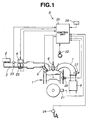
- the fuel injection control system S of this embodiment is for a cylinder direct injection spark-ignition internal combustion engine of an automotive vehicle.
- the engine comprises an engine main body 1 mounted on a vehicle body (not shown).
- the engine main body 1 has a plurality of cylinders each of which is supplied with air through an intake air passage 3 from an air filter 2 under control of an electronically controlled throttle valve 4.
- a combustion chamber (not identified) is defined in each cylinder.
- the throttle valve 4 is operated such that its opening degree is controlled in accordance with a signal from a control unit 20 under the action of a step motor or the like.
- An electromagnetically controlled fuel injector valve 5 is disposed to the combustion chamber so as to directly inject fuel (gasoline) into the combustion chamber.
- the fuel injector valve 5 is arranged to inject fuel (pressure-regulated to have a predetermined pressure) in accordance with an injection pulse signal which is output from the control unit 20 in timed relation to engine revolution in intake stroke or/and in compression stroke of each cylinder.
- the fuel injector valve 5 is opened to accomplish such fuel injection upon a solenoid of the fuel injector valve 5 being energized.
- the injected fuel from the fuel injector valve 5 is spread in the combustion chamber to form homogeneous air-fuel mixture in the combustion chamber, in case of fuel injection in intake stroke of the cylinder.
- the injected fuel from the fuel injector valve 5 is concentrated around a spark plug 6 to form stratified air-fuel mixture in the combustion chamber, in case of fuel injection in compression stroke of the cylinder.
- Such air-fuel mixture is ignited by the spark plug 6 and in accordance with an ignition signal output from the control unit 20 thereby accomplishing homogeneous charge combustion or stratified charge combustion.
- the homogeneous charge combustion includes homogeneous charge combustion at stoichiometric air-fuel ratio, and homogeneous charge combustion at lean air-fuel ratio (20 : 1 to 30 : 1).
- the stratified charge combustion includes stratified charge combustion at lean air-fuel ratio (about 40 : 1).
- the engine main body 1 is provided with an exhaust gas passage 7 through which exhaust gas from each cylinder is discharged.
- a catalytic converter 8 is disposed in the exhaust gas passage 7 to purify exhaust gas.
- the control unit 20 includes a microcomputer having a CPU, a ROM, a RAM, a A/D converter, input and output interfaces and the like.
- a variety of sensors are provided to output signals which are to be input to the control unit 20. Such sensors will be discussed.
- a crankangle sensor 21 is provided to detect a rotational angle of a crankshaft (not identified) of the engine main body 1, and another crankangle sensor 22 is provided to detect a rotational angle of a camshaft (not identified).
- An airflow meter 23 is disposed in the intake air passage 3 upstream of the throttle valve 4 so as to detect an intake air quantity Qa (a quantity of intake air to be introduced to the cylinders).
- An accelerator sensor 24 is provided to detect an accelerator operation amount ACC or depression amount of an accelerator pedal (not identified) of the vehicle.
- a throttle position sensor 25 is provided to detect an opening degree TVO of the throttle valve 4, and includes an idle switch (not identified) which is switched ON at a fully closed position of the throttle valve 4.
- An engine coolant temperature sensor 26 is provided to detect a temperature Tw of engine coolant.
- An oxygen (O 2 ) sensor 27 is disposed in the exhaust gas passage 7 so as to output a signal depending upon a rich mixture (low oxygen content in exhaust gas) or a lean mixture (high oxygen content in exhaust gas), i.e., depending upon the oxygen content in exhaust gas in the exhaust gas passage 7.
- the oxygen content represents (actual) air-fuel ratio of air-fuel mixture in the combustion chamber or in the cylinder.
- control unit 20 functions to input the signal from the above-mentioned sensors and makes predetermined calculation processing under the action of the microcomputer, and output a variety of command signals which control the opening degree of the electronically controlled throttle valve 4, a fuel injection quantity (a quantity of fuel to be injected to the combustion chamber) of the fuel injector valve 5, and a spark timing of the spark plug 6.
- a homogeneous comb. equivalent ratio setting section A is provided to set an equivalent ratio (stoichiometric air-fuel ratio / actual air-fuel ratio) during homogeneous charge combustion, in accordance with an engine operating condition such as the engine speed, engine load and/or the like. It will be understood that the equivalent ratio is in close relation to the actual air-fuel ratio of air-fuel mixture in the combustion chamber.
- a stratified comb. equivalent ratio setting section B is provided to set the equivalent ratio during stratified charge combustion, in accordance with an engine operating condition such as the engine speed, the engine load and/or the like.
- a homogeneous comb. / stratified comb. judging section C is provided to make a judgement as to which one of homogeneous charge combustion and stratified charge combustion is to be carried out, in accordance with the engine operating condition.
- a changeover section D is provided to change over the equivalent ratio from one set by the homogeneous comb. equivalent ratio setting section A to one set by the stratified comb. equivalent ratio, and vice versa so as to set the equivalent ratio in accordance with a judgment result of the homogeneous comb. / stratified comb. judging section C. The thus set equivalent ratio is output.
- a retarding section E is provided to apply a delay processing onto the equivalent ratio output from the changeover section D.
- the delay processing is applied for the following reasons: If the equivalent ratio is changed over stepwise in accordance with changeover of combustion condition, a stepwise torque change occurs owing to delay of change in intake air quantity after the changeover action for intake air quantity. In view of this, under the action of this retarding section E, the equivalent ratio is gradually changed corresponding to the delay of change in intake air quantity thereby to allow engine torque to smoothly vary.
- a fuel injection quantity calculating section F is provided to calculate a fuel injection quantity basically in accordance with the intake air quantity, the engine speed and the equivalent ratio to which the delay processing has been applied, thus to obtain a basic value of the fuel injection quantity.
- the thus obtained fuel injection quantity basic value is corrected with the engine coolant temperature, an equivalent ratio correction coefficient, and the like, thus obtaining the fuel injection quantity.
- An allocation rate calculating section G is provided to calculate an allocation rate at which a first fuel injection quantity (for homogeneous charge combustion) of fuel is injected in intake stroke and an allocation rate at which a second fuel injection quantity (for stratified charge combustion) of fuel is injected in compression stroke when the changeover in the combustion condition (homogeneous charge combustion or stratified charge combustion) is being made, in accordance with either one of the equivalent ratio at the changeover section D and the equivalent ratio at the retarding section E.
- An intake stroke injection quantity calculating section H and a compression stroke injection quantity calculating section I are provided to divide the fuel injection quantity (or a total fuel injection quantity for each stroke of a piston in the cylinder) calculated by the fuel injection quantity calculating section F into the first fuel injection quantity and the second fuel injection quantity, in accordance with the allocation rates calculated by the allocation rate calculating section G.
- the intake stroke injection quantity calculating section H and the compression stroke injection quantity calculating section I calculate the first fuel injection quantity and the second fuel injection quantity, respectively.
- the first fuel injection quantity is on the intake stroke, while the second fuel injection quantity is on the compression stroke.
- injection timing calculating section J is provided to calculate a fuel injection timing (or a timing at which fuel is injected from the fuel injector valve 5) during homogeneous charge combustion.
- a stratified comb. injection timing calculating section K is provided to calculate the fuel injection timing during stratified charge combustion.
- An injection pulse generating section L is provided to generate a fuel injection pulse (or a pulse-width time for which the fuel injector valve is opened to inject fuel) having a pulse width corresponding to the fuel injection quantity on intake stroke, at the fuel injection timing for homogeneous charge combustion calculated by the homogeneous comb.
- injection timing calculating section J and similarly to generate a fuel injection pulse having a pulse width corresponding to the fuel injection quantity on compression stroke, at a fuel injection timing for stratified charge combustion calculated by the stratified comb.
- injection timing calculating section K is provided to generate a fuel injection pulse (or a pulse-width time for which the fuel injector valve is opened to inject fuel) having a pulse width corresponding to the fuel injection quantity on intake stroke, at the fuel injection timing for homogeneous charge combustion calculated by the homogeneous comb.
- first and second fuel injections are carried out respectively on intake and compression strokes.
- the first and second fuel injection quantities respectively at the first and second fuel injections are divided respectively at the above-mentioned allocation rate.
- a routine for setting allocations rates of the fuel injection quantities is discussed with a flowchart of Fig. 3 and a time chart of Fig. 4. This routine is executed every a predetermined time, for example, 10 ms.
- either one of stratified charge combustion and homogeneous charge combustion is selected in accordance with the engine operating condition such as engine speed, engine load and/or the like (at the homogeneous comb. / stratified comb. judging section C).
- the engine operating condition such as engine speed, engine load and/or the like
- a homogeneous charge combustion condition which requires homogeneous charge combustion or a stratified charge combustion condition which requires stratified charge combustion is judged in accordance with the engine operating condition.
- step S3 at which the equivalent ratio for stratified charge combustion is calculated, for example, by searching a map (at the stratified comb. equivalent ratio setting section B).
- step S4 In case that homogeneous charge combustion has been selected at the step S2, flow goes to a step S4 at which the equivalent ratio for homogeneous charge combustion is calculated, for example, by searching a map (at the homogeneous comb. equivalent ratio setting section A).
- a weight Fload is made to obtain a weight Fload to a present value of a weighted average used in the delay processing for the calculated equivalent ratio, for example, by searching a map (as shown in Fig. 5) in accordance with the engine operating condition such as engine speed and the throttle valve opening degree TVO.
- the equivalent ratio is gradually increased from a mapped value under the delay processing so as to approach a target value (equivalent ratio) for the homogeneous charge combustion.
- the fuel injection timing ITS for stratified charge combustion and the fuel injection timing ITS for homogeneous charge combustion are calculated, for example, by searching a map (as shown in Fig. 6 or Fig. 7) for each of the homogeneous and stratified charge combustions, in accordance with the engine speed N and the engine load.
- the fuel injection timing ITS for homogeneous charge combustion is set.
- the flow goes to a step S11 at which the allocation rate for homogeneous charge combustion is set at 100 % while the allocation rate for stratified charge combustion is set at 0 % , so that whole the fuel injection quantity Te calculated at the step S7 is injected on intake stroke of the piston thereby accomplishing complete homogeneous charge combustion.
- the flow goes to a step S12 at which the equivalent ratio T ⁇ d is smaller or not than a decision value for changeover to stratified charge combustion which decision value is larger by a predetermined value ⁇ 2 than an upper limit value T ⁇ S for stratified charge combustion.
- the equivalent ratio T ⁇ dn is judged to be smaller than the decision value
- the flow goes to a step S13 at which the allocation rate for the homogeneous charge combustion is set at 0 % while the allocation rate for the stratified charge combustion is set at 100 %, so that whole the fuel injection quantity Te calculated at the step S7 is injected on compression stroke of the piston thereby accomplishing complete stratified charge combustion.
- the equivalent ratio T ⁇ dn is judged to be smaller than the decision value for changeover to stratified charge combustion (i.e., in case of the equivalent ratio T ⁇ dn being within a range of [ T ⁇ S + ⁇ ⁇ T ⁇ d ⁇ T ⁇ H - ⁇ 1] at the step S12, the following decision is made: the present status has corresponded to the combustion condition changeover time of the present invention so that two times fuel injections are to be made respectively on intake and compression strokes. Then, the flow goes to a step S14 in which the two times fuel injections are accomplished.
- the allocation rate (of fuel injection quantity) for homogeneous charge combustion is searched from a table shown in Fig. 8A, in accordance with the above internally divided ratio T ⁇ dn.
- the allocation rate of fuel injection quantity increases with an increase in the equivalent ratio T ⁇ dn, in which the allocation rate is set within a range of from a minimum value larger a considerable amount than 0 % to a maximum value smaller a considerable amount than 100 %. This is because precision of the fuel injection quantity of fuel from the fuel injector valve 5 cannot be maintained at a suitable value if the fuel injection quantity becomes too small.
- the table in Fig. 8A may be replaced with a table shown in Fig. 8B which table has been set upon taking regions of stratified charge combustion and homogeneous charge combustion.
- Fig. 8A may be replaced with a table shown in Fig. 8C which table sets the allocation rate in terms of deviation in equivalent ratio from stratified charge combustion and homogeneous charge combustion.
- Fig. 8C which table sets the allocation rate in terms of deviation in equivalent ratio from stratified charge combustion and homogeneous charge combustion.
- the divided fuel quantities to be injected respectively on intake and compression strokes are allocated in accordance with the allocation rate which is calculated in accordance with the equivalent ratio, and therefore the fuel quantities can be appropriately allocated in accordance with the equivalent ratio thereby effectively preventing misfire and unstable combustion while extending limits of combustion at the equivalent ratio.
- the time duration in which the divided injections of fuel are carried out is set within a range of the equivalent ratio, and more specifically within a range of the equivalent ratio which range has the predetermined deviations from the equivalent ratios at times before and after the combustion condition changeover. This prevents air-fuel ratio in the cylinder from becoming excessively rich or excessively lean, thereby ensuring stable combustion in the cylinder.
- the opening degree of the throttle valve 4 is controlled in accordance with the decision of the combustion changeover.
- the throttle valve opening degree is controlled to decrease upon decision of the combustion condition changeover.
- the intake air quantity of air to be supplied to the cylinder gradually changes (gradually decreases in the example shown in Fig. 4).
- Engine torque is maintained at an approximately constant level under control in which the equivalent ratio is gradually changed according to delay of change in intake air quantity.
- spark timing (spark advance angle) for the spark plug 6 is gradually changed in accordance with a change in the equivalent ratio while being set corresponding to stratified charge combustion since stratified charge combustion is basically carried out during the time in which the divided fuel injection is made.
- the spark timing is gradually retarded as the combustion condition changeover comes near. Then, the spark timing is changed stepwise in timed relation to the changeover from the divided fuel injection to a single fuel injection for homogeneous charge combustion, in which the spark timing is advanced when the changeover is made to homogeneous charge combustion. During a time period in which the equivalent ratio is being changed under homogeneous charge combustion, the spark timing is controlled to gradually change.
- the fuel injection control routine is executed in accordance with the allocation rate of the fuel injection quantity. This routine is executed when the fuel injection timing ITS for homogeneous charge combustion has come.
- a flow goes to a step S22 at which judgment is made as to whether the allocation rate is 0 % or not.
- the divided (two times) fuel injection is to be accomplished and therefore the flow goes to a step S23.
- spark timing ADVS which has been calculated according to a separate spark timing calculation routine is set.
- This spark timing ADVS is for stratified charge combustion since the combustion condition in case that the two times fuel injections are carried out is basically stratified charge combustion.
- step S26 fuel injection at the fuel injection quantity Ti1 is initiated at the fuel injection timing ITH on intake stroke.
- the fuel injection timing ITS for stratified charge combustion is set.
- the fuel injection quantity Ti2 on compression stroke is set.
- a spark timing ADVH for homogeneous charge combustion
- a separate spark timing calculation routine is set.
- the flow goes to a step S25.
- spark ignition is made at the spark timing ADVH thereby to accomplish homogeneous charge combustion.
- step S25 at which a spark timing ADVS (for stratified charge combustion) is set, and thereafter spark ignition is made at the spark timing ADVS thereby to accomplish stratified charge combustion.
- a spark timing ADVS for stratified charge combustion
- Fig. 11 shows the spark timing calculation routine which is to be executed at intervals of a predetermined time (for example, 10 ms).
- the spark timing ADVH for homogeneous charge combustion
- the spark timing ADVS for stratified charge combustion
Landscapes
- Engineering & Computer Science (AREA)
- Chemical & Material Sciences (AREA)
- Combustion & Propulsion (AREA)
- Mechanical Engineering (AREA)
- General Engineering & Computer Science (AREA)
- Electrical Control Of Air Or Fuel Supplied To Internal-Combustion Engine (AREA)
Applications Claiming Priority (6)
| Application Number | Priority Date | Filing Date | Title |
|---|---|---|---|
| JP176239/97 | 1997-07-01 | ||
| JP17623997A JP3677947B2 (ja) | 1997-07-01 | 1997-07-01 | 内燃機関の燃料噴射制御装置 |
| JP17623997 | 1997-07-01 | ||
| JP17624097 | 1997-07-01 | ||
| JP17624097A JP3677948B2 (ja) | 1997-07-01 | 1997-07-01 | 内燃機関の燃料噴射制御装置 |
| JP176240/97 | 1997-07-01 |
Publications (3)
| Publication Number | Publication Date |
|---|---|
| EP0889218A2 true EP0889218A2 (fr) | 1999-01-07 |
| EP0889218A3 EP0889218A3 (fr) | 2000-06-14 |
| EP0889218B1 EP0889218B1 (fr) | 2007-08-08 |
Family
ID=26497240
Family Applications (1)
| Application Number | Title | Priority Date | Filing Date |
|---|---|---|---|
| EP98112067A Expired - Lifetime EP0889218B1 (fr) | 1997-07-01 | 1998-06-30 | Système de commande d'injection de carburant pour moteurs à combustion interne |
Country Status (4)
| Country | Link |
|---|---|
| US (1) | US6058905A (fr) |
| EP (1) | EP0889218B1 (fr) |
| KR (1) | KR100317159B1 (fr) |
| DE (1) | DE69838199T2 (fr) |
Cited By (5)
| Publication number | Priority date | Publication date | Assignee | Title |
|---|---|---|---|---|
| WO1999067524A3 (fr) * | 1998-06-24 | 2000-03-09 | Bosch Gmbh Robert | Procede de fonctionnement d'un moteur a combustion interne |
| EP1081364A3 (fr) * | 1999-08-31 | 2003-02-05 | Nissan Motor Co., Ltd. | Commande pour moteur à combustion interne à allumage commandé et à injection directe |
| WO2003031792A1 (fr) * | 2001-10-05 | 2003-04-17 | Robert Bosch Gmbh | Procede de fonctionnement d'un moteur a combustion interne en particulier d'un vehicule automobile |
| WO2005024213A1 (fr) * | 2003-09-05 | 2005-03-17 | Siemens Aktiengesellschaft | Procede et dispositif pour commander le passage entre deux modes de fonctionnement d'un moteur a etincelles et a injection directe |
| EP2058500A3 (fr) * | 2007-11-12 | 2015-01-07 | Hitachi Ltd. | Appareil de contrôle de moteur |
Families Citing this family (17)
| Publication number | Priority date | Publication date | Assignee | Title |
|---|---|---|---|---|
| DE19813379A1 (de) * | 1998-03-26 | 1999-10-07 | Bosch Gmbh Robert | Verfahren zum Betreiben einer Brennkraftmaschine insbesondere eines Kraftfahrzeugs |
| JP3819609B2 (ja) * | 1998-09-25 | 2006-09-13 | 株式会社日立製作所 | 補間制御手段を備えたエンジン制御装置 |
| JP4279398B2 (ja) * | 1999-04-28 | 2009-06-17 | 三菱自動車工業株式会社 | 筒内噴射型内燃機関 |
| AU2001261245A1 (en) * | 2000-05-08 | 2001-11-20 | Cummins, Inc. | Multiple operating mode engine and method of operation |
| JP4250856B2 (ja) * | 2000-05-24 | 2009-04-08 | 三菱自動車工業株式会社 | 筒内噴射型内燃機関 |
| KR100427294B1 (ko) * | 2000-12-30 | 2004-04-17 | 현대자동차주식회사 | 가솔린 직접 분사 엔진의 공연비 상태 판정방법 |
| KR100435648B1 (ko) * | 2000-12-30 | 2004-06-12 | 현대자동차주식회사 | 가솔린 직접분사 엔진의 흡기 유동 제어 밸브 제어 시스템 |
| KR100418765B1 (ko) * | 2000-12-30 | 2004-02-18 | 현대자동차주식회사 | 가솔린 직접분사 엔진의 전자 흡기 제어 밸브 제어 시스템 |
| KR100412641B1 (ko) * | 2000-12-30 | 2003-12-31 | 현대자동차주식회사 | 가솔린 직접 분사 엔진의 운전 영역 천이 제어방법 |
| US6687597B2 (en) * | 2002-03-28 | 2004-02-03 | Saskatchewan Research Council | Neural control system and method for alternatively fueled engines |
| DE10334401B3 (de) * | 2003-07-28 | 2004-11-25 | Siemens Ag | Verfahren und Vorrichtung zur Steuerung des Übergangs zwischen dem Normalbetrieb und dem Betrieb mit Schubabschaltung eines mit Kraftstoff-Direkteinspritzung betriebenen Ottomotors |
| US20060151891A1 (en) * | 2005-01-13 | 2006-07-13 | Aspen Engineering Services, Llc | Venturi induction for homogeneous charge compression ignition engines |
| JP4643323B2 (ja) * | 2005-03-18 | 2011-03-02 | トヨタ自動車株式会社 | 内燃機関の制御装置 |
| US7530342B2 (en) * | 2006-09-07 | 2009-05-12 | Ford Global Technologies, Llc | Approach for facilitating fuel evaporation in cylinder of an internal combustion engine |
| DE102010012744B4 (de) * | 2010-03-25 | 2021-06-10 | Volkswagen Ag | Verfahren zum Betreiben einer Brennkraftmaschine mit Betriebsartenübergang |
| JP6011582B2 (ja) * | 2014-06-23 | 2016-10-19 | トヨタ自動車株式会社 | 内燃機関の制御装置 |
| EP3640462B1 (fr) * | 2017-06-15 | 2021-01-27 | Nissan Motor Co., Ltd. | Dispositif de commande et procédé de commande pour moteur à injection directe |
Family Cites Families (9)
| Publication number | Priority date | Publication date | Assignee | Title |
|---|---|---|---|---|
| JPS5937236A (ja) * | 1982-08-26 | 1984-02-29 | Nissan Motor Co Ltd | 燃料噴射時期制御方法 |
| EP0369480A3 (fr) * | 1988-11-18 | 1991-01-02 | Toyota Jidosha Kabushiki Kaisha | Un moteur à combustion interne |
| US5078107A (en) * | 1990-03-30 | 1992-01-07 | Fuji Jukogyo Kabushiki Kaisha | Fuel injection control system for an internal combustion engine |
| JP2861233B2 (ja) * | 1990-04-11 | 1999-02-24 | トヨタ自動車株式会社 | 筒内直接噴射式火花点火機関の機関制御装置 |
| JP2765305B2 (ja) * | 1991-10-25 | 1998-06-11 | トヨタ自動車株式会社 | 内燃機関 |
| JP2917617B2 (ja) * | 1991-10-28 | 1999-07-12 | トヨタ自動車株式会社 | 内燃機関 |
| JPH06280660A (ja) * | 1993-01-29 | 1994-10-04 | Mazda Motor Corp | エンジンの燃料制御装置 |
| JPH08312438A (ja) * | 1995-05-12 | 1996-11-26 | Yamaha Motor Co Ltd | 2サイクルエンジンにおける燃料噴射方法及び燃料噴射制御装置 |
| JP3152106B2 (ja) * | 1995-05-16 | 2001-04-03 | 三菱自動車工業株式会社 | 筒内噴射型火花点火式内燃エンジンの制御装置 |
-
1998
- 1998-06-30 DE DE69838199T patent/DE69838199T2/de not_active Expired - Lifetime
- 1998-06-30 EP EP98112067A patent/EP0889218B1/fr not_active Expired - Lifetime
- 1998-06-30 KR KR1019980025490A patent/KR100317159B1/ko not_active Expired - Lifetime
- 1998-07-01 US US09/108,409 patent/US6058905A/en not_active Expired - Lifetime
Cited By (9)
| Publication number | Priority date | Publication date | Assignee | Title |
|---|---|---|---|---|
| WO1999067524A3 (fr) * | 1998-06-24 | 2000-03-09 | Bosch Gmbh Robert | Procede de fonctionnement d'un moteur a combustion interne |
| US6394065B1 (en) | 1998-06-24 | 2002-05-28 | Robert Bosch Gmbh | Method for operating an internal combustion engine |
| EP1081364A3 (fr) * | 1999-08-31 | 2003-02-05 | Nissan Motor Co., Ltd. | Commande pour moteur à combustion interne à allumage commandé et à injection directe |
| EP1710422A3 (fr) * | 1999-08-31 | 2012-08-15 | Nissan Motor Co., Ltd. | Commande pour moteur à combustion interne à allumage commandé et à injection directe |
| WO2003031792A1 (fr) * | 2001-10-05 | 2003-04-17 | Robert Bosch Gmbh | Procede de fonctionnement d'un moteur a combustion interne en particulier d'un vehicule automobile |
| WO2005024213A1 (fr) * | 2003-09-05 | 2005-03-17 | Siemens Aktiengesellschaft | Procede et dispositif pour commander le passage entre deux modes de fonctionnement d'un moteur a etincelles et a injection directe |
| US7328683B2 (en) | 2003-09-05 | 2008-02-12 | Siemens Aktiengesellschaft | Method and device for controlling the transition in a direct injection internal combustion engine |
| KR101107479B1 (ko) * | 2003-09-05 | 2012-01-19 | 콘티넨탈 오토모티브 게엠베하 | 직접분사식 스파크 점화 엔진의 전환 제어 방법 및 장치 |
| EP2058500A3 (fr) * | 2007-11-12 | 2015-01-07 | Hitachi Ltd. | Appareil de contrôle de moteur |
Also Published As
| Publication number | Publication date |
|---|---|
| DE69838199T2 (de) | 2007-11-22 |
| EP0889218A3 (fr) | 2000-06-14 |
| EP0889218B1 (fr) | 2007-08-08 |
| KR19990013481A (ko) | 1999-02-25 |
| US6058905A (en) | 2000-05-09 |
| KR100317159B1 (ko) | 2002-02-19 |
| DE69838199D1 (de) | 2007-09-20 |
Similar Documents
| Publication | Publication Date | Title |
|---|---|---|
| US6058905A (en) | Fuel injection control system for internal combustion engine | |
| EP0879955B1 (fr) | Commande d'un moteur transitoire entre deux états à allumage par étincelle | |
| EP1277942B1 (fr) | Procédé et système de contrôle d'un moteur à injection directe | |
| EP1533507B1 (fr) | Commande d'injection de carburant pour moteur à combustion | |
| US5979397A (en) | Control apparatus for direct injection spark ignition type internal combustion engine | |
| JP4836088B2 (ja) | 圧縮自己着火式内燃機関の制御装置および制御方法 | |
| EP0826869B1 (fr) | Système pour le chauffage de gaz d'échappement d'un moteur à combustion à injection dans les cylindres | |
| US6026779A (en) | Apparatus for controlling internal combustion engine | |
| JP3521632B2 (ja) | 内燃機関の制御装置 | |
| US7168238B2 (en) | Method for heating up a catalyst in combustion engines with direct fuel injection | |
| EP1647690B1 (fr) | Procédé et dispositif de commande de combustion pour un moteur à injection directe et allumage commandé | |
| EP0924420A2 (fr) | Régulateur de couple pour un moteur à combustion interne | |
| US20020059919A1 (en) | Fuel injection control system and method and engine control unit for internal combustion engine | |
| EP1164276B1 (fr) | Moteur à combustion interne avec support externe pour auto-allumage stable | |
| US20020043239A1 (en) | Hybrid operating mode for DISI engines | |
| US5277165A (en) | Stratified charge internal combustion engine with fuel injection time controlling function | |
| US7198025B2 (en) | In-cylinder injection type spark-ignition internal combustion engine | |
| JP3677947B2 (ja) | 内燃機関の燃料噴射制御装置 | |
| JP3677948B2 (ja) | 内燃機関の燃料噴射制御装置 | |
| US11952955B2 (en) | Method for operating a multiple direct injection internal combustion engine and mass-based switching of the number of injections | |
| US20020179068A1 (en) | Method of operating an internal -combustion engine | |
| JPH08261046A (ja) | 内燃機関の空燃比制御装置 |
Legal Events
| Date | Code | Title | Description |
|---|---|---|---|
| PUAI | Public reference made under article 153(3) epc to a published international application that has entered the european phase |
Free format text: ORIGINAL CODE: 0009012 |
|
| 17P | Request for examination filed |
Effective date: 19980630 |
|
| AK | Designated contracting states |
Kind code of ref document: A2 Designated state(s): DE FR GB |
|
| AX | Request for extension of the european patent |
Free format text: AL;LT;LV;MK;RO;SI |
|
| PUAL | Search report despatched |
Free format text: ORIGINAL CODE: 0009013 |
|
| AK | Designated contracting states |
Kind code of ref document: A3 Designated state(s): AT BE CH CY DE DK ES FI FR GB GR IE IT LI LU MC NL PT SE |
|
| AX | Request for extension of the european patent |
Free format text: AL;LT;LV;MK;RO;SI |
|
| AKX | Designation fees paid |
Free format text: DE FR GB |
|
| 17Q | First examination report despatched |
Effective date: 20040212 |
|
| GRAP | Despatch of communication of intention to grant a patent |
Free format text: ORIGINAL CODE: EPIDOSNIGR1 |
|
| GRAS | Grant fee paid |
Free format text: ORIGINAL CODE: EPIDOSNIGR3 |
|
| GRAA | (expected) grant |
Free format text: ORIGINAL CODE: 0009210 |
|
| AK | Designated contracting states |
Kind code of ref document: B1 Designated state(s): DE FR GB |
|
| REG | Reference to a national code |
Ref country code: GB Ref legal event code: FG4D |
|
| REF | Corresponds to: |
Ref document number: 69838199 Country of ref document: DE Date of ref document: 20070920 Kind code of ref document: P |
|
| ET | Fr: translation filed | ||
| PLBE | No opposition filed within time limit |
Free format text: ORIGINAL CODE: 0009261 |
|
| STAA | Information on the status of an ep patent application or granted ep patent |
Free format text: STATUS: NO OPPOSITION FILED WITHIN TIME LIMIT |
|
| 26N | No opposition filed |
Effective date: 20080509 |
|
| REG | Reference to a national code |
Ref country code: FR Ref legal event code: PLFP Year of fee payment: 19 |
|
| REG | Reference to a national code |
Ref country code: FR Ref legal event code: PLFP Year of fee payment: 20 |
|
| PGFP | Annual fee paid to national office [announced via postgrant information from national office to epo] |
Ref country code: FR Payment date: 20170511 Year of fee payment: 20 Ref country code: GB Payment date: 20170628 Year of fee payment: 20 |
|
| PGFP | Annual fee paid to national office [announced via postgrant information from national office to epo] |
Ref country code: DE Payment date: 20170627 Year of fee payment: 20 |
|
| REG | Reference to a national code |
Ref country code: DE Ref legal event code: R071 Ref document number: 69838199 Country of ref document: DE |
|
| REG | Reference to a national code |
Ref country code: GB Ref legal event code: PE20 Expiry date: 20180629 |
|
| PG25 | Lapsed in a contracting state [announced via postgrant information from national office to epo] |
Ref country code: GB Free format text: LAPSE BECAUSE OF EXPIRATION OF PROTECTION Effective date: 20180629 |