EP0889344A1 - Câble à fibres optiques en forme de ruban pour interconnexion - Google Patents
Câble à fibres optiques en forme de ruban pour interconnexion Download PDFInfo
- Publication number
- EP0889344A1 EP0889344A1 EP98305126A EP98305126A EP0889344A1 EP 0889344 A1 EP0889344 A1 EP 0889344A1 EP 98305126 A EP98305126 A EP 98305126A EP 98305126 A EP98305126 A EP 98305126A EP 0889344 A1 EP0889344 A1 EP 0889344A1
- Authority
- EP
- European Patent Office
- Prior art keywords
- fiber
- ribbon
- spacing
- fiber optic
- optic cable
- Prior art date
- Legal status (The legal status is an assumption and is not a legal conclusion. Google has not performed a legal analysis and makes no representation as to the accuracy of the status listed.)
- Granted
Links
Images


Classifications
-
- G—PHYSICS
- G02—OPTICS
- G02B—OPTICAL ELEMENTS, SYSTEMS OR APPARATUS
- G02B6/00—Light guides; Structural details of arrangements comprising light guides and other optical elements, e.g. couplings
- G02B6/44—Mechanical structures for providing tensile strength and external protection for fibres, e.g. optical transmission cables
- G02B6/4401—Optical cables
- G02B6/4403—Optical cables with ribbon structure
- G02B6/4404—Multi-podded
-
- G—PHYSICS
- G02—OPTICS
- G02B—OPTICAL ELEMENTS, SYSTEMS OR APPARATUS
- G02B6/00—Light guides; Structural details of arrangements comprising light guides and other optical elements, e.g. couplings
- G02B6/44—Mechanical structures for providing tensile strength and external protection for fibres, e.g. optical transmission cables
- G02B6/4401—Optical cables
- G02B6/4403—Optical cables with ribbon structure
-
- G—PHYSICS
- G02—OPTICS
- G02B—OPTICAL ELEMENTS, SYSTEMS OR APPARATUS
- G02B6/00—Light guides; Structural details of arrangements comprising light guides and other optical elements, e.g. couplings
- G02B6/44—Mechanical structures for providing tensile strength and external protection for fibres, e.g. optical transmission cables
- G02B6/4401—Optical cables
- G02B6/4415—Cables for special applications
Definitions
- the present invention relates to a fiber optic cable for use in a cable assembly comprising fiber optic connectors connectorized to a ribbon in the cable.
- Electrical and fiber optic components are used to transmit data signals in telecommunication, computer, and closed circuit television systems.
- Conventional components for example, opto-electrical and electro-optical transducers, are used in such systems to interface between electrical and fiber optic modes of signal transmission.
- Electrical systems may experience crosstalk between the signal wires thereof. This type of electrical crosstalk occurs due to electromagnetic fields surrounding the transmitting wires. The electromagnetic fields due to one given circuit induce currents and electromotive forces in other circuits spaced close enough to the disturbing electrical circuit to be affected. For example, electrical crosstalk affecting a telephone line may result in the undesired mixing of caller conversations over the affected line. Spacing the electrical wires of different circuits apart tends to reduce electrical crosstalk.
- optical-based systems use confined light as the information carrying medium rather than electricity, optical-based systems are not as susceptible to crosstalk and therefore do not require a significant crosstalk type spacing between the optical fibers.
- Opto-electrical and electro-optical transducers generally require electrical wires to be spaced apart sufficiently enough to avoid crosstalk.
- respective ends of optical fibers in single fiber cables are connected to such transducers by placing them in housings comprising spaced fiber receiving apertures.
- Another method is to use a two-fiber optical ribbon with a 250 ⁇ m spacing between the fibers whereby the fibers are separated, stripped, and individually connectorized.
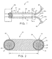
- Figure 1 shows a fiber optic cable assembly including a fiber optic cable according to the present invention.
- Figure 2 shows a cross section of a fiber optic ribbon of the fiber optic cable of Figure 1.
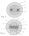
- Figure 3 shows a cross section of the fiber optic cable of Figure 1 taken across line 3-3.
- Figure 4 shows a cross section of a fiber optic cable according to a second embodiment of the present invention.
- Figure 5 shows a cross section of a fiber optic cable according to a third embodiment of the present invention.
- Figure 6 shows a cross section of a fiber optic ribbon according to a fourth embodiment of the present invention.
- Figure 7 shows a cross section of a fiber optic ribbon according to a fifth embodiment of the present invention.
- Fiber optic cable assembly 10 comprises conventional single fiber connectors 80 and 82, a conventional dual fiber connector 84, and a fan-out housing 86.
- Single fiber connectors 80 and 82 may be of the FC Ultra PC type made by the SIECORTM Corporation of Hickory, North Carolina.
- Dual fiber connector 84 is of the type used to interface with, for example, an opto-electrical or electro-optical transducer (not shown).
- Dual fiber connector 84 is a conventional connector, for example, as disclosed in US-A-5214730, which is hereby incorporated by reference herein in its entirety.
- Fiber optic cable 50 comprises a fiber optic ribbon 20.
- Ribbon 20 includes optical fibers 24, a variable spacing section 23, and a transition section 27 inside connector housing 86.
- Optical fibers 24 are spaced at a nominal fiber-to-fiber distance, herein defined as spacing S.
- Variable spacing section 23 comprises sub-carrier sections 22a and 22b comprising plastic tubes, e.g. furcation tubing, the spacing of which is variable.
- Each carrier section 22 includes an optical fiber 24 with a core and a cladding layer 26 therearound.
- Cladding layer 26 is surrounded by a protective coating 25.
- Protective coating 25 is surrounded by an identification ink layer 27.
- a separation layer 28 is strategically disposed between ink layer 25 and a peelable ribbon matrix layer 29.
- Separation layer 28 comprises a suitable material, for example, a TBIITM or silicone based material.
- Matrix layer 29 comprises, for example, a UV curable acrylate material or any suitable thermoplastic material, e.g. a PVC material.
- Matrix layer 29 constrains fibers 24 to spacing S.
- the nominal fiber-to-fiber distance defined by spacing S advantageously comprises an integer multiple of the nominal outside diameter (OD) of the fiber, for example, spacing S would nominally be 500 ⁇ m, 750 ⁇ m, 1000 ⁇ m, or etc.
- the 750 ⁇ m spacing would permit ribbon 20 to be connectorized to a conventional four fiber connector (not shown).
- Separation layer 28 allows a craftsman to remove matrix layer 29 from separation layer 28, whereby sub-carrier sections 22a and 22b are no longer constrained by ribbon matrix layer 29 ( Figure 1).
- ribbon 20 will yet comprise a generally nominal fiber-to-fiber spacing S, which spacing matches the spacing needed in an electrical system to avoid crosstalk.
- the present invention advantageously permits two fibers 24 to be connectorized in one step.
- the use of ribbon 20 with a dual fiber connector 84 therefore, reduces installation time and material costs.
- Sub-carrier sections 22a and 22b, no longer constrained by matrix layer 29, may be variably spaced and individually connectorized to respective connectors 80 and 82.
- Ribbon 20 is preferably part of an inside or outside plant optical cable 50 (Figure 3).
- Optical cable 50 comprises strength member 52 located about ribbon 20.
- a jacket 54 surrounds strength members 52.
- jacket 54 and strength members 52 would be stripped away from variable spacing section 23 so that sub-carrier sections 22a and 22b would extend out of fan-out housing 86 for termination with respective connectors 80,82.
- a ribbon 30 comprises carrier sections 32 with a separation layer 38 disposed between a ribbon matrix layer 39 and an ink layer 35 (Figure 4).
- Spacer fibers 36 are strategically placed between carrier sections 32 thereby defining the desired spacing S between carrier sections 32, as in the first embodiment of the present invention.
- Ribbon 30 may comprise part of an inside or outside plant optical cable 60.
- Optical cable 60 comprises strength members 62 located about ribbon 30.
- a jacket 64 surrounds strength members 62.
- Figure 5 shows a third embodiment of the present invention, wherein a fiber optic cable 70 includes carrier sections 42 each having a separation layer 48 between a ribbon matrix layer 49 and an ink layer 45.
- a protective layer 46 surrounds a glass core and cladding 44.
- a UV acrylate material 47 is over-coated to a desired diameter thereby spacing fibers 44 at the desired spacing S, as in the first embodiment of the present invention.
- Ribbon 40 may comprise part of an inside or outside plant optical cable 70.
- Optical cable 70 comprises strength members 72 which surround ribbon 40.
- a jacket 74 surrounds strength members 72.
- Figure 6 shows a fourth embodiment of the present invention wherein a ribbon 90 comprises carrier sections 92 each having a separation layer 98 disposed between a ribbon matrix layer 99 and an ink layer 97.
- Cladding 96 surrounds a core 94, and cladding 96 is surrounded by a protective layer 95.
- Ribbon 90 includes a radius of curvature R, which advantageously lessens the cross sectional area of ribbon matrix 99 between carrier sections 92.
- the amount of matrix layer material per unit length of cable is also reduced, consequently, the unit cost to produce ribbon 90 may be less as compared to the unit cost of ribbon 20.
- ribbon 90 may comprise part of an inside or outside plant optical cable.
- FIG. 7 shows a ribbon 200 with carrier sections 222.
- Each carrier section 222 includes an optical fiber core 224 having a fiber cladding layer 226 therearound.
- Cladding layer 226 is surrounded by a protective coating 225.
- Protective coating 225 is surrounded by an identification ink layer 227.
- a separation layer 228 is strategically disposed between ink layer 225 and a peelable ribbon matrix layer 229.
- Separation layer 228 comprises a suitable material, for example, a TBIITM or a silicone based material.
- Matrix layer 229 comprises, for example, a suitable thermoplastic material, e.g. a PVC material. Matrix layer 229 constrains fibers 224 to a spacing S, as in the first embodiment of the present invention.
- the nominal fiber-to-fiber distance of spacing S is an integer multiple of the nominal outside diameter (OD) of the fiber.
- a 750 ⁇ m spacing advantageously permits ribbon 200 to be connectorized to a conventional four fiber connector (not shown).
- ribbon 200 may be surrounded by a jacket and strength members.
- a thickness t, medially located between carrier sections 222 is about 15% to 75% of a thickness T of carrier sections 222.
- the fiber optic cables of the present invention are adaptable for use with boots attached to connectors or fan-out housings.
Landscapes
- Physics & Mathematics (AREA)
- General Physics & Mathematics (AREA)
- Optics & Photonics (AREA)
- Light Guides In General And Applications Therefor (AREA)
Applications Claiming Priority (2)
| Application Number | Priority Date | Filing Date | Title |
|---|---|---|---|
| US884934 | 1997-06-30 | ||
| US08/884,934 US5966489A (en) | 1997-06-30 | 1997-06-30 | Fiber optic ribbon interconnect cable |
Publications (2)
| Publication Number | Publication Date |
|---|---|
| EP0889344A1 true EP0889344A1 (fr) | 1999-01-07 |
| EP0889344B1 EP0889344B1 (fr) | 2003-09-03 |
Family
ID=25385759
Family Applications (1)
| Application Number | Title | Priority Date | Filing Date |
|---|---|---|---|
| EP98305126A Expired - Lifetime EP0889344B1 (fr) | 1997-06-30 | 1998-06-29 | Câble à fibres optiques en forme de ruban pour interconnexion |
Country Status (5)
| Country | Link |
|---|---|
| US (1) | US5966489A (fr) |
| EP (1) | EP0889344B1 (fr) |
| JP (1) | JPH1172670A (fr) |
| CA (1) | CA2238438A1 (fr) |
| DE (1) | DE69817694D1 (fr) |
Cited By (2)
| Publication number | Priority date | Publication date | Assignee | Title |
|---|---|---|---|---|
| WO2001075498A3 (fr) * | 2000-03-30 | 2002-02-14 | Corning Cable Sys Llc | Ensemble de fibres optiques a caracteristique d'interface |
| US6389214B1 (en) | 2001-05-17 | 2002-05-14 | 3M Innovative Properties Company | Furcation apparatus for optical fibers |
Families Citing this family (28)
| Publication number | Priority date | Publication date | Assignee | Title |
|---|---|---|---|---|
| US6449412B1 (en) * | 1998-06-30 | 2002-09-10 | Corning Cable Systems Llc | Fiber optic ribbon interconnect cable |
| US6295401B1 (en) | 1999-12-21 | 2001-09-25 | Siecor Operations, Llc | Optical fiber ribbon cables |
| US6379053B1 (en) | 2000-05-30 | 2002-04-30 | Infineon Technologies North America Corp. | Multi-fiber fiber optic connectors |
| US6584257B1 (en) | 2000-12-27 | 2003-06-24 | Corning Cable Systems, Llc | Fiber optic assembly and method of making same |
| US6714713B2 (en) | 2002-03-15 | 2004-03-30 | Corning Cable Systems Llc | Optical fiber having a low-shrink buffer layer and methods of manufacturing the same |
| US6909829B2 (en) | 2002-03-28 | 2005-06-21 | Corning Cable Systems Llc | Buffered optical fiber ribbon |
| US7186031B2 (en) * | 2003-10-16 | 2007-03-06 | 3M Innovative Properties Company | Optical interconnect device |
| EP1875287A1 (fr) | 2005-04-19 | 2008-01-09 | ADC Telecommunications, Inc. | Procede et bouche de rebouclage |
| US20100079248A1 (en) * | 2008-09-29 | 2010-04-01 | Johannes Ian Greveling | Optical fiber connector assembly with wire-based RFID antenna |
| TW201038166A (en) * | 2008-11-14 | 2010-10-16 | Corning Inc | Equipment cabinet having improved space utilization |
| WO2010102201A2 (fr) | 2009-03-05 | 2010-09-10 | Adc Telecommunications, Inc. | Procédés, systèmes et dispositifs destinés à intégrer une technologie sans fil dans un réseau à fibres optiques |
| US7703990B1 (en) | 2009-04-23 | 2010-04-27 | Corning Cable Systems Llc | Furcation bodies and fiber optic assemblies using the same |
| US8818156B2 (en) | 2010-03-30 | 2014-08-26 | Corning Cable Systems Llc | Multiple channel optical fiber furcation tube and cable assembly using same |
| US9078287B2 (en) | 2010-04-14 | 2015-07-07 | Adc Telecommunications, Inc. | Fiber to the antenna |
| US8410909B2 (en) | 2010-07-09 | 2013-04-02 | Corning Incorporated | Cables and connector assemblies employing a furcation tube(s) for radio-frequency identification (RFID)-equipped connectors, and related systems and methods |
| US8961035B2 (en) | 2010-08-02 | 2015-02-24 | Adc Telecommunications, Inc. | Architecture for a fiber optic network |
| US8958673B2 (en) | 2011-05-27 | 2015-02-17 | Corning Cable Systems Llc | Molded fiber optic cable furcation assemblies, and related fiber optic components, assemblies, and methods |
| CA2871108C (fr) | 2012-05-02 | 2019-09-17 | Afl Telecommunications Llc | Cables optiques de petit diametre et ronds ayant une structure de fibres optiques de type ruban |
| US20160041356A1 (en) | 2013-04-07 | 2016-02-11 | Tyco Electronics (Shanghai) Co., Ltd. | Fiber optic connection assembly |
| US20160124173A1 (en) | 2013-06-07 | 2016-05-05 | Adc Telecommunications, Inc. | Telecommunications connection device |
| CN105676380B (zh) | 2014-11-21 | 2019-07-12 | 泰科电子(上海)有限公司 | 光缆布线系统和光缆连接组件 |
| US10712519B2 (en) | 2017-06-28 | 2020-07-14 | Corning Research & Development Corporation | High fiber count pre-terminated optical distribution assembly |
| US11256051B2 (en) | 2018-01-15 | 2022-02-22 | Prysmian S.P.A. | Flexible optical-fiber ribbon |
| RU2759664C1 (ru) * | 2018-01-15 | 2021-11-16 | Призмиан С.П.А. | Способ изготовления гибкой волоконно-оптической ленты и лента |
| US11460652B2 (en) | 2020-12-22 | 2022-10-04 | Prysmian S.P.A. | Optical-fiber ribbon with adhesive-free gaps |
| US11860429B2 (en) | 2020-12-22 | 2024-01-02 | Prysmian S.P.A. | Optical-fiber ribbon with spaced optical-fiber units |
| US11442238B2 (en) | 2020-12-22 | 2022-09-13 | Prysmian S.P.A. | Optical-fiber ribbon with spaced optical-fiber units |
| US20230168441A1 (en) * | 2021-11-30 | 2023-06-01 | Corning Research & Development Corporation | Unjacketed fiber optic cable assembly, and cable assembly including connector with travel limited ferrule |
Citations (5)
| Publication number | Priority date | Publication date | Assignee | Title |
|---|---|---|---|---|
| JPH01245205A (ja) * | 1988-03-28 | 1989-09-29 | Fujikura Ltd | 分割型光ファイバテープ |
| EP0349206A2 (fr) * | 1988-06-30 | 1990-01-03 | AT&T Corp. | Matrice combinée de médias de transmission |
| US4893893A (en) * | 1986-01-31 | 1990-01-16 | American Telephone And Telegraph Co., At&T Bell Laboratories | Strengthened buffered optical fiber |
| US5208889A (en) * | 1991-10-24 | 1993-05-04 | W. L. Gore & Associates, Inc. | Optical fiber ribbon cable and assembly thereof with a connector |
| EP0762171A1 (fr) * | 1995-08-01 | 1997-03-12 | AT&T Corp. | Câbles à fibre optique sub-sous miniatures et appareils et méthodes pour leur fabrication |
Family Cites Families (6)
| Publication number | Priority date | Publication date | Assignee | Title |
|---|---|---|---|---|
| GB1570624A (en) * | 1975-12-11 | 1980-07-02 | Western Electric Co | Optical fibre transmission arrangements |
| DE3606626A1 (de) * | 1986-02-28 | 1987-09-03 | Siemens Ag | Flachbandleitung mit mehreren lichtwellenleitern und verfahren zu deren herstellung |
| KR880003203A (ko) * | 1986-08-05 | 1988-05-14 | 나까하라 쯔네오 | 광파이버 심선 |
| JP2573633B2 (ja) * | 1987-11-26 | 1997-01-22 | 住友電気工業株式会社 | テープ状光ファイバ心線の製造装置 |
| JPH0256510A (ja) * | 1988-08-23 | 1990-02-26 | Sumitomo Electric Ind Ltd | テープ状光フアイバ心線の製造方法 |
| US5136683A (en) * | 1989-09-14 | 1992-08-04 | Mitsubishi Rayon Company, Ltd. | Flame-retardant cable |
-
1997
- 1997-06-30 US US08/884,934 patent/US5966489A/en not_active Expired - Lifetime
-
1998
- 1998-05-25 CA CA002238438A patent/CA2238438A1/fr not_active Abandoned
- 1998-06-29 DE DE69817694T patent/DE69817694D1/de not_active Expired - Lifetime
- 1998-06-29 EP EP98305126A patent/EP0889344B1/fr not_active Expired - Lifetime
- 1998-06-30 JP JP10185023A patent/JPH1172670A/ja active Pending
Patent Citations (5)
| Publication number | Priority date | Publication date | Assignee | Title |
|---|---|---|---|---|
| US4893893A (en) * | 1986-01-31 | 1990-01-16 | American Telephone And Telegraph Co., At&T Bell Laboratories | Strengthened buffered optical fiber |
| JPH01245205A (ja) * | 1988-03-28 | 1989-09-29 | Fujikura Ltd | 分割型光ファイバテープ |
| EP0349206A2 (fr) * | 1988-06-30 | 1990-01-03 | AT&T Corp. | Matrice combinée de médias de transmission |
| US5208889A (en) * | 1991-10-24 | 1993-05-04 | W. L. Gore & Associates, Inc. | Optical fiber ribbon cable and assembly thereof with a connector |
| EP0762171A1 (fr) * | 1995-08-01 | 1997-03-12 | AT&T Corp. | Câbles à fibre optique sub-sous miniatures et appareils et méthodes pour leur fabrication |
Non-Patent Citations (2)
| Title |
|---|
| "PARALLEL OPTICAL FIBER CABLE FOR OPTICAL TRANSCEIVERS WITH A GAP BETWEEN GROUPS OF FIBERS WITHIN THE CABLE", IBM TECHNICAL DISCLOSURE BULLETIN, vol. 39, no. 1, 1 January 1996 (1996-01-01), pages 321/322, XP000556419 * |
| PATENT ABSTRACTS OF JAPAN vol. 013, no. 583 (P - 981) 22 December 1989 (1989-12-22) * |
Cited By (3)
| Publication number | Priority date | Publication date | Assignee | Title |
|---|---|---|---|---|
| WO2001075498A3 (fr) * | 2000-03-30 | 2002-02-14 | Corning Cable Sys Llc | Ensemble de fibres optiques a caracteristique d'interface |
| US6535673B1 (en) | 2000-03-30 | 2003-03-18 | Corning Cable Systems Llc | Optical fiber arrays having an interface characteristic |
| US6389214B1 (en) | 2001-05-17 | 2002-05-14 | 3M Innovative Properties Company | Furcation apparatus for optical fibers |
Also Published As
| Publication number | Publication date |
|---|---|
| JPH1172670A (ja) | 1999-03-16 |
| US5966489A (en) | 1999-10-12 |
| DE69817694D1 (de) | 2003-10-09 |
| CA2238438A1 (fr) | 1998-12-30 |
| EP0889344B1 (fr) | 2003-09-03 |
Similar Documents
| Publication | Publication Date | Title |
|---|---|---|
| EP0889344A1 (fr) | Câble à fibres optiques en forme de ruban pour interconnexion | |
| US5970195A (en) | Fiber optic cable furcation unit | |
| EP3550342B1 (fr) | Connecteur à fibre optique | |
| CA2151071C (fr) | Appareil limiteur de pliage pour cable | |
| US6619853B2 (en) | Optical fiber interconnection system | |
| US6438299B1 (en) | Assembly and method for furcating optical fibers | |
| US6295401B1 (en) | Optical fiber ribbon cables | |
| EP1146374A3 (fr) | Câble à rubans pour fibres optiques à épanouissement | |
| US7630610B2 (en) | Loop back plug with protective dust cap | |
| WO2004061509A1 (fr) | Cavalier optique multi-fibres flexible | |
| US7354202B1 (en) | Fiber optic cable connector | |
| EP3754397A1 (fr) | Ensemble connecteur de fibres optiques avec sous-ensemble de tube de sertissage et procédé d'utilisation | |
| EP3822679B1 (fr) | Préparation de câbles à fibres optiques pour applications de conduit | |
| EP1182484B1 (fr) | Dispositif de séparation et de regroupement de fibres optiques | |
| US20020012504A1 (en) | Angled fiber optic connector | |
| GB2049220A (en) | Optical fiber terminator and means and method for centering optical fiber | |
| EP0137667B1 (fr) | Dispositif de retenue des fibres optiques | |
| EP4050391A1 (fr) | Assemblage pour câble | |
| EP4231075A1 (fr) | Tube de sortance pour une bifurcation d'un câble à fibre optique et procédé associé | |
| EP4055432B1 (fr) | Ensemble de déploiement pour câble à fibres optiques | |
| KR100350483B1 (ko) | 팬아웃 블럭 | |
| EP1680698A1 (fr) | Ancrage pour cable a fibre optique | |
| Brown et al. | Assembly and Method for Furcating Optical Fibers | |
| Brown | Fiber Optic Cable Furcation Unit. | |
| Kato | Advanced optical fiber connectors |
Legal Events
| Date | Code | Title | Description |
|---|---|---|---|
| PUAI | Public reference made under article 153(3) epc to a published international application that has entered the european phase |
Free format text: ORIGINAL CODE: 0009012 |
|
| AK | Designated contracting states |
Kind code of ref document: A1 Designated state(s): DE FR GB |
|
| AX | Request for extension of the european patent |
Free format text: AL;LT;LV;MK;RO;SI |
|
| 17P | Request for examination filed |
Effective date: 19990628 |
|
| AKX | Designation fees paid |
Free format text: DE FR GB |
|
| 17Q | First examination report despatched |
Effective date: 19990819 |
|
| GRAG | Despatch of communication of intention to grant |
Free format text: ORIGINAL CODE: EPIDOS AGRA |
|
| GRAG | Despatch of communication of intention to grant |
Free format text: ORIGINAL CODE: EPIDOS AGRA |
|
| GRAH | Despatch of communication of intention to grant a patent |
Free format text: ORIGINAL CODE: EPIDOS IGRA |
|
| GRAH | Despatch of communication of intention to grant a patent |
Free format text: ORIGINAL CODE: EPIDOS IGRA |
|
| RAP1 | Party data changed (applicant data changed or rights of an application transferred) |
Owner name: CSS HOLDINGS, INC. |
|
| RAP1 | Party data changed (applicant data changed or rights of an application transferred) |
Owner name: CCS HOLDINGS, INC. |
|
| GRAA | (expected) grant |
Free format text: ORIGINAL CODE: 0009210 |
|
| AK | Designated contracting states |
Kind code of ref document: B1 Designated state(s): DE FR GB |
|
| PG25 | Lapsed in a contracting state [announced via postgrant information from national office to epo] |
Ref country code: FR Free format text: LAPSE BECAUSE OF FAILURE TO SUBMIT A TRANSLATION OF THE DESCRIPTION OR TO PAY THE FEE WITHIN THE PRESCRIBED TIME-LIMIT Effective date: 20030903 |
|
| REG | Reference to a national code |
Ref country code: GB Ref legal event code: FG4D |
|
| REF | Corresponds to: |
Ref document number: 69817694 Country of ref document: DE Date of ref document: 20031009 Kind code of ref document: P |
|
| PG25 | Lapsed in a contracting state [announced via postgrant information from national office to epo] |
Ref country code: DE Free format text: LAPSE BECAUSE OF FAILURE TO SUBMIT A TRANSLATION OF THE DESCRIPTION OR TO PAY THE FEE WITHIN THE PRESCRIBED TIME-LIMIT Effective date: 20031204 |
|
| PG25 | Lapsed in a contracting state [announced via postgrant information from national office to epo] |
Ref country code: GB Free format text: LAPSE BECAUSE OF NON-PAYMENT OF DUE FEES Effective date: 20040629 |
|
| RAP2 | Party data changed (patent owner data changed or rights of a patent transferred) |
Owner name: CCS HOLDINGS, INC. |
|
| PLBE | No opposition filed within time limit |
Free format text: ORIGINAL CODE: 0009261 |
|
| STAA | Information on the status of an ep patent application or granted ep patent |
Free format text: STATUS: NO OPPOSITION FILED WITHIN TIME LIMIT |
|
| 26N | No opposition filed |
Effective date: 20040604 |
|
| EN | Fr: translation not filed | ||
| GBPC | Gb: european patent ceased through non-payment of renewal fee |
Effective date: 20040629 |