EP0889395A2 - Reduzierung der Verzweigungsfehler durch einen Pipeline-Prozessor mit einer Schaltung mit geringer Schaltungsgrösse - Google Patents
Reduzierung der Verzweigungsfehler durch einen Pipeline-Prozessor mit einer Schaltung mit geringer Schaltungsgrösse Download PDFInfo
- Publication number
- EP0889395A2 EP0889395A2 EP98304886A EP98304886A EP0889395A2 EP 0889395 A2 EP0889395 A2 EP 0889395A2 EP 98304886 A EP98304886 A EP 98304886A EP 98304886 A EP98304886 A EP 98304886A EP 0889395 A2 EP0889395 A2 EP 0889395A2
- Authority
- EP
- European Patent Office
- Prior art keywords
- instruction
- decoded
- address
- code
- buffer
- Prior art date
- Legal status (The legal status is an assumption and is not a legal conclusion. Google has not performed a legal analysis and makes no representation as to the accuracy of the status listed.)
- Granted
Links
Images


Classifications
-
- G—PHYSICS
- G06—COMPUTING OR CALCULATING; COUNTING
- G06F—ELECTRIC DIGITAL DATA PROCESSING
- G06F9/00—Arrangements for program control, e.g. control units
- G06F9/06—Arrangements for program control, e.g. control units using stored programs, i.e. using an internal store of processing equipment to receive or retain programs
- G06F9/30—Arrangements for executing machine instructions, e.g. instruction decode
- G06F9/38—Concurrent instruction execution, e.g. pipeline or look ahead
- G06F9/3802—Instruction prefetching
- G06F9/3808—Instruction prefetching for instruction reuse, e.g. trace cache, branch target cache
- G06F9/381—Loop buffering
-
- G—PHYSICS
- G06—COMPUTING OR CALCULATING; COUNTING
- G06F—ELECTRIC DIGITAL DATA PROCESSING
- G06F9/00—Arrangements for program control, e.g. control units
- G06F9/06—Arrangements for program control, e.g. control units using stored programs, i.e. using an internal store of processing equipment to receive or retain programs
- G06F9/30—Arrangements for executing machine instructions, e.g. instruction decode
- G06F9/32—Address formation of the next instruction, e.g. by incrementing the instruction counter
- G06F9/322—Address formation of the next instruction, e.g. by incrementing the instruction counter for non-sequential address
- G06F9/323—Address formation of the next instruction, e.g. by incrementing the instruction counter for non-sequential address for indirect branch instructions
-
- G—PHYSICS
- G06—COMPUTING OR CALCULATING; COUNTING
- G06F—ELECTRIC DIGITAL DATA PROCESSING
- G06F9/00—Arrangements for program control, e.g. control units
- G06F9/06—Arrangements for program control, e.g. control units using stored programs, i.e. using an internal store of processing equipment to receive or retain programs
- G06F9/30—Arrangements for executing machine instructions, e.g. instruction decode
- G06F9/32—Address formation of the next instruction, e.g. by incrementing the instruction counter
- G06F9/322—Address formation of the next instruction, e.g. by incrementing the instruction counter for non-sequential address
- G06F9/325—Address formation of the next instruction, e.g. by incrementing the instruction counter for non-sequential address for loops, e.g. loop detection or loop counter
Definitions
- the present invention relates to a processor for executing machine-language instruction sequences using pipeline processing, and especially relates to a processor for executing branch processing at high speed.
- Pipeline processing is known as one of the fundamental techniques for achieving high-speed processing by a Central Processing Unit (CPU: hereinafter processor).
- CPU Central Processing Unit
- pipeline processing a process dealing with one instruction is divided into smaller stages (pipeline stages), each pipeline stage being processed in parallel to speed up the processing.
- this technique is not effective in executing branch instructions which are used in loops because a stall can occur. This phenomenon is called a branch hazard. Due to branch hazards, the operational performance of pipeline processing does not reach an optimal level.
- code that includes the first instruction of a loop is stored into a buffer just before the loop is started.
- the code is retrieved from the buffer and the first instruction is decoded and executed.
- the first instruction does not need to be fetched from an external memory each time the loop is executed, so that the branch hazards can be avoided.
- the conventional processor described above has a drawback that its circuit is of large scale, since the processor needs a specific circuit for avoiding the branch hazards.
- the processor has to be equipped with an adder that is specifically used for calculating a fetch address of code that follows the code including the first instruction of the loop while the code including the first instruction is stored into the buffer just before the loop is started.
- the calculated fetch address is then stored into an address buffer.
- the processor also has to be equipped with a subtractor that is specifically used for calculating an address of the first instruction to be decoded using the fetch address that is retrieved from the address buffer when the processing branches from the last instruction to the first instruction.
- a processor for executing a program loop at a high speed using a register instruction which is set immediately before the program loop and a loop instruction which is set at an end of the program loop
- the processor including: a fetch unit for fetching code from a memory; a decoding unit for decoding an instruction included in the fetched code; and an execution unit for executing the decoded instruction, the decoding unit including a decoded instruction counter for storing and updating a pointer specifying an instruction that is being decoded, the pointer being a sum of a fixed shift value and an address of the instruction that is being decoded, and the execution unit including: a storage unit for storing, when the decoding unit decodes the register instruction, code at a start of the program loop that has been fetched by the fetch unit into a first buffer and storing the pointer stored in the decoded instruction counter into a second buffer; and a high-speed branch unit for having the fetch unit fetch code, when the loop instruction has been decoded by the de
- the fixed shift value may be equal to a storage size of the first buffer.
- the decoded instruction counter when initialized, may store a sum of a start address and the fixed shift value.
- the execution unit may further include a branch unit for sending, when a branch instruction with an absolute address is decoded by the decoding unit, the absolute address to a fetched instruction counter in the fetch unit and sending a value, obtained by adding the fixed shift value to the absolute address, to the decoded instruction counter.
- a branch unit for sending, when a branch instruction with an absolute address is decoded by the decoding unit, the absolute address to a fetched instruction counter in the fetch unit and sending a value, obtained by adding the fixed shift value to the absolute address, to the decoded instruction counter.
- the branch unit may send a value, obtained by adding the relative address to the pointer stored in the decoded instruction counter, to the decoded instruction counter and send a value, obtained by subtracting the fixed shift value from the value which is sent to the decoded instruction counter, to the fetched instruction counter.
- branch instructions with an absolute address and a relative address are executed using the pointer stored in the decoded instruction counter.
- the fetched instruction counter may include a register for storing a fetch address and an adder for incrementing the fetch address stored in the register, wherein, when the branch instruction with the absolute address is decoded by the decoding unit, the branch unit has the adder in the fetched instruction counter add the fixed shift value to the absolute address and sends an adding result to the decoded instruction counter.
- the calculation of the pointer to be stored in the decoded instruction counter can be performed not by the execution unit but by the adder in the fetched instruction counter.
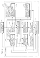
- Fig. 1 is a block diagram showing the construction of the processor of the first embodiment of the present invention.
- the figure also shows an external memory 11 which stores an instruction sequence (program) that is to be processed by the processor 13.
- instruction sequence program
- the processor 13 fetches at least one instruction from the external memory 11, and decodes and executes the instructions one by one.
- the processor 13 is constructed in such a way as to execute a loop at high speed with small-scale hardware.
- the loop is specified by a combination of a branch target information register instruction (hereinafter, register instruction) and a high-speed loop instruction.
- the register instruction is set immediately before a first instruction of the loop and instructs the processor to register code that includes at least one instruction that is located at the start of the loop into the processor.
- code refers to code that expresses the instructions.
- the high-speed loop instruction is set at the end of the loop and instructs the processor to branch to the first instruction of the loop if a condition included in the high-speed loop instruction is satisfied, wherein the first instruction has been stored in the processor according to the register instruction.
- the register instruction and the high-speed loop instruction are respectively written as "setlb” and "lcc" in mnemonic form.
- the processor 13 includes an instruction fetch unit 14, an instruction decoding unit 15, an instruction execution unit 16, and a branch target information storage unit 17. Each component of the processor 13 operates in synchronization with a clock signal from a clock generator (not illustrated).
- the instruction fetch unit 14, the instruction decoding unit 15, and the instruction execution unit 16 compose an instruction pipeline, where each unit operates in parallel in synchronization with the clock signal.
- the instruction fetch unit 14 fetches code from the external memory 11, stores it into a fetched instruction buffer 142, and sends the stored code to the instruction decoding unit 15.
- the instruction fetch unit 14 includes a fetched instruction counter (FIC) 141, the fetched instruction buffer (FIB) 142, and a selection unit 143.
- the FIC 141 stores a fetch address from which code is to be fetched and sends the fetch address to the external memory 11. After the code has been fetched, the FIC 141 is incremented to update the fetch address. When the high-speed loop instruction is executed, the fetch address in the FIC 141 is updated to an address sent from the branch target information storage unit 17 according to control signals from the instruction decoding unit 15.
- the FIB 142 is an FIFO (First In First Out) memory for storing the code fetched from the external memory 11.
- the selection unit 143 selects code stored in the branch target information storage unit 17 only when the high-speed loop instruction is executed. When other instructions are executed, the selection unit 143 selects code in the FIB 142. The selection unit 143 then outputs the selected code to the instruction decoding unit 15.
- the instruction decoding unit 15 decodes an instruction included in the code sent from the instruction fetch unit 14 and outputs the decoding result which is composed of control signals for controlling the operations of the instruction fetch unit 14, the instruction decoding unit 15, the instruction execution unit 16, and the branch target information storage unit 17.
- the instruction decoding unit 15 includes a decoded instruction counter (DIC) 151, a decoded instruction buffer (DIB) 152, and an instruction decoder 153.
- the DIC 151 stores and updates a pointer that is the sum of an address of an instruction which is being decoded and a predetermined shift value.
- the DIC 151 is initialized to a value that is the sum of a start address and the shift value 4.
- the DIC 151 is incremented by the word length of the decoded instruction and as a result updated to a pointer that is the sum of an address of an instruction to be decoded next and the shift value 4.
- the pointer in the DIC 151 is updated to an address sent from the branch target information storage unit 17 in accordance with control signals from the instruction decoding unit 15.
- the shift value needs to be equal to a storage size (the number of bytes) of a branch target instruction register 171 in the branch target information storage unit 17. For example, if the storage size of the branch target instruction register 171 is 8 bytes, the pointer in the DIC 151 will be the sum of a currently-decoded instruction address and the shift value 8.
- the DIB 152 is a register for storing an instruction that has been sent from the FIB 142 and that is being decoded.
- the instruction decoder 153 decodes the instruction stored in the DIB 152 and outputs control signals for controlling the instruction fetch unit 14, the instruction decoding unit 15, the instruction execution unit 16, and the branch target information storage unit 17 in accordance with the decoding result.
- the instruction decoder 153 controls the instruction execution unit 16 to adjust the pointer in the DIC 151 by appropriately adding/subtracting the shift value 4 according to a content of the instruction.
- the above adjustment is not necessary when the high-speed loop instruction is decoded.
- the instruction execution unit 16 is composed of an ALU (arithmetic logic unit), a shifter, and other components, and performs operations and controls the components of the processor 13 according to the control signals sent from the instruction decoding unit 15.
- the instruction execution unit 16 also inputs/outputs control signals on signal lines connected to the processor 13 (not illustrated).
- the branch target information storage unit 17 stores branch target information when the instruction decoding unit 15 has decoded the register instruction.
- the branch target information means code (4 bytes in the present embodiment) starting from the first instruction of the loop stored in the FIB 142, to which the last instruction of the loop is to branch.
- the branch target information storage unit 17 includes the branch target instruction register (BIR) 171 and a branch target fetch address register (BAR) 172.
- the BIR 171 is a register for storing the first 4 bytes of code from the FIB 142 when the instruction decoding unit 15 decodes the register instruction. By doing so, the first 4 bytes of the loop are stored in the BIR 171.
- the BIR 171 is also referred to as the loop instruction buffer.
- the BAR 172 is a register for storing a pointer from the DIC 151 in the next cycle when the instruction decoding unit 15 has decoded the register instruction.
- This pointer is the sum of a currently-decoded instruction address and the storage size of the BIR 171 (4 bytes) and thus corresponds to an address of code that follows the code stored in the BIR 171. That is to say, the pointer stored in the BAR 172 is a fetch address from which code is to be fetched by the instruction fetch unit 14 after a branch from the high-speed loop instruction is executed.
- the BAR 172 is also referred to as the loop address buffer.
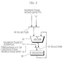
- Fig. 2 shows an example of the construction of the DIC 151.
- the DIC 151 includes an adder 31, a register 32, and selectors 33 and 34.
- the adder 31 adds the fixed value 4 to the start address of the register 32.
- the adder 31 usually adds the word length (the number of bytes) of a decoded instruction to a pointer in the register 32. By doing so, the register 32 is updated to a pointer that is "(an address of an instruction to be decoded)+4". When a branch instruction has been executed, the pointer in the register 32 is updated to a branch target address that is inputted via the selector 33.
- Fig. 3 is a flowchart showing the processing of the register instruction which is set immediately before the loop, the high-speed loop instruction which is set at the end of the loop, and other instructions.
- Step S31 When a decoding result by the instruction decoder 153 is the register instruction (setlb) (Step S31), the first 4 bytes of code are sent from the FIB 142 to the BIR 171 (Step S32), and then the pointer in the DIC 151 is sent to the BAR 172 (Step S33).
- the BIR 171 stores the first 4 bytes of code of the loop
- the BAR 172 stores the address of the code that follows the first 4 bytes of code.
- the processor 13 proceeds to the next instruction execution stage (Step S34).
- Step S31 When the decoding result by the instruction decoder 153 is the high-speed loop instruction (lcc) (Step S31), it is judged whether a branch condition is satisfied (Step S35).
- the first 4 bytes of code of the loop are sent from the BIR 171 to the DIB 152 (Step S36), and the address is sent from the BAR 172 to the DIC 151 (Step S37) and to the FIC 141 (Step S38).
- the FIC 141 stores the fetch address of the code following the first 4 bytes of code
- the DIC 151 stores a pointer which is the sum of the address of the currently decoded instruction (first instruction) and 4.
- the instruction fetch unit 14 does not need to fetch the first instruction which is the branch target, no branch hazard will occur. Also, the FIC 141 can easily obtain the address of the code that follows the first 4 bytes of code from the BAR 172 without conducting specific address calculations.
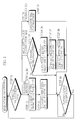
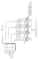
- Fig. 4 is a block diagram showing the detailed constructions of the selection unit 143 and the BIR 171. The figure also shows the FIB 142. Note that each instruction of the program has a variable word length (an integer multiple of 8 bits).
- the FIB 142 is constructed as a queue which shifts fetched code in units of 8 bits, the queue preferably having about 16 levels.
- the FIB 142 outputs the first 4 bytes of the queue to the DIB 152 via the selection unit 143 in each cycle of the instruction decoding stage.
- the instruction decoding unit 15 decodes the 4 bytes of code and notifies the FIB 142 of the instruction word length (expressed as a number of bytes for one instruction starting from the start of the 4 bytes of code).
- the FIB 142 shifts the code by the notified word length towards the front of the queue and so deletes the decoded instruction. By doing so, a first byte of an instruction is usually at the front of the queue (it is not necessarily the case immediately after a branch from the high-speed loop instruction is executed).
- the BIR 171 includes a queue 171a and a selection control unit 171b.
- the queue 171a is constructed as a 4-level queue which circularly shifts code in units of 8 bits.
- the queue 171a stores the first 4 bytes of code of the FIB 142, which are then outputted to the DIB 152 via the selection unit 143 after the high-speed loop instruction is decoded.
- the instruction decoding unit 15 decodes the 4 bytes of code and notifies the queue 171a of the instruction word length via the selection control unit 171b.
- the queue 171a shifts the code by the notified word length circularly towards the front of the queue.
- the queue 171a repeats the shifting until the 4 bytes make one round, so as to recover the original storage state where the 4 bytes are stored in the queue 171a according to the register instruction. This operation is performed again next time a branch from the high-speed loop instruction is executed.
- the selection control unit 171b controls the selection unit 143 to select the 4 bytes of code stored in the queue 171a instead of the 4 bytes of code stored in the FIB 142.
- the selection control unit 171b has the queue 171a output all 4 bytes of code to the instruction decoding unit 15 via the selection unit 143 immediately after the branch.
- the instruction decoding unit 15 decodes the code and notifies the queue 171a of the instruction word length.
- the selection control unit 171b has the queue 171a shift the code by the notified word length circularly and counts the number of valid bytes of code in the queue 171a. Then the selection control unit 171b controls the selection unit 143 according to the number of valid bytes in the next instruction decoding stage.
- the selection unit 143 includes selectors 143a-143d. When the high-speed loop instruction has been executed and the 4 bytes of code sent from the BIR 171 have been decoded by the instruction decoding unit 15, the selection unit 143 selects following 4 bytes of code by combining valid code in the queue 171a and subsequent code in the FIB 142.
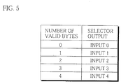
- Fig. 5 shows the selection logic of the selectors 143a-143d.
- the selectors 143a-143d output 4 bytes of code by combining the valid code in the queue 171a and the subsequent code in the FIB 142.
- Fig. 5 shows the case when four 5 input-1 output (“5 to 1") 8-bit selectors are used, a combination of a "2 to 1", a "3 to 1", a “4 to 1", and a "5 to 1" selectors may alternatively be used.
- the DIC 151 stores a pointer which is the sum of a currently-decoded instruction address and the fixed value 4. Accordingly, when executing instructions for reading from or writing into the DIC 151, it is necessary to adjust the pointer by adding or subtracting the value 4. This adjustment is necessary when executing addressing instructions other than the high-speed loop instruction.
- Fig. 6 shows the operation contents of branch instructions.
- the simple branch instruction “branch abs_adrs”, the subroutine call instruction “call abs_adrs”, and the subroutine return instruction “ret” are representative instructions for absolute addressing
- the simple branch instruction “branch rel_adrs” is a representative instruction for relative addressing.
- the code “abs_adrs” indicates a 32-bit absolute address
- the code “rel_adrs” indicates an 8-bit or 16-bit relative address.
- the instruction execution unit 16 When processing the simple branch instruction "branch abs_adrs", the instruction execution unit 16 stores the absolute address "abs_adrs” into the FIC 141 (Operation 601), adds the fixed value 4 to the absolute address "abs_adrs”, and stores the sum into the DIC 151 (Operation 602). By doing so, the fetch, decoding, and execution processing will be started from an instruction specified by the absolute address "abs_adrs". Thus, to execute a branch instruction which specifies a branch target by absolute addressing, the value obtained by adding 4 to the absolute address is set in the DIC 151.
- the instruction execution unit 16 When processing the subroutine call instruction "call abs_adrs", the instruction execution unit 16 stores the absolute address "abs_adrs" into the FIC 141 (Operation 603), adds a decoded instruction word length to the pointer in the DIC 151 (Operation 604), subtracts 4 from the sum, pushes the subtracting result onto a stack (not illustrated) (Operation 605), and stores the sum of the absolute address "abs_adrs" and 4 into the DIC 151 (Operation 606).
- the subtracting result corresponds to an address of an instruction which was being decoded during the execution of the subroutine call instruction "call abs_adrs".
- the subtracting result corresponds to an address of an instruction subsequent to the subroutine call instruction "call abs_adrs".
- the value obtained by subtracting 4 from the pointer in the DIC 151 is pushed onto the stack.
- the instruction execution unit 16 pops the instruction address following the subroutine call instruction "call abs_adrs" from the stack, stores the address into the FIC 141 (Operation 607), adds 4 to the address, and stores the sum into the DIC 151 (Operation 608).
- the sum of the value pushed onto the stack and 4 is stored back into the DIC 151.
- the instruction execution unit 16 When processing the simple branch instruction "branch rel_adrs", the instruction execution unit 16 adds the relative address "rel_adrs" to the pointer of the DIC 151, stores the sum into the DIC 151 (Operation 609), subtracts 4 from the sum, and stores the subtracting result into the FIC 141 (Operation 610).
- the value obtained by subtracting 4 from the new pointer in the DIC 151 is set in the FIC 141. Note that this subtraction of 4 from the pointer in the DIC 151 to set the address in the FIC 141 is unnecessary when executing the high-speed loop instruction.
- the DIC 151 can simply be updated to the sum of the absolute address and 4, while the FIC 141 can be updated to the absolute address.
- the DIC 151 can simply be updated to the sum of the relative address and the pointer in the DIC 151, while the FIC 141 can be updated to the value obtained by subtracting 4 from this sum.
- the above addition and subtraction using the fixed value 4 are performed by the ALU in the instruction execution unit 16.
- the instruction execution unit 16 performs address calculations for all branch instructions other than the high-speed loop instruction.
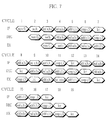
- Fig. 7 shows a flow of a pipeline formed when executing the program shown below.
- instruction address instruction comment 1000 mov 0,i transfer 0 into i 1002 setlb store branch target L : label 1003 add a,b,c transfer a+b into c 1005 mul a,b,d transfer a ⁇ b into d 1007 add i,1,i add 1 to i 1009 comp i,3 compare i and 3 100B lcc L branch to L if i ⁇ 3
- instruction address shows lowest 16 bits of a 32-bit address in hexadecimal
- instruction is written in mnemonic form
- “comment” shows instruction contents.
- the processing from the instruction (add a,b,c) that follows the register instruction (setlb) to the high-speed loop instruction (lcc) is a loop which is repeated three times.
- Fig. 7 the horizontal axis shows time in cycle units, while the vertical axis shows three pipeline stages that are IF, DEC, and EX.
- IF stage shows an instruction at the front of the FIB 142, though it shows an instruction at the front of the BIR 171 in cycles 8, 9, 13, and 14.
- DEC stage shows a currently decoded instruction which is stored in the DIB 152.
- EX stage shows an instruction which is currently being executed by the instruction execution unit 16.
- the DIC 151 stores a pointer that is the sum of a currently-decoded instruction address and the shift value 4. Accordingly, it is unnecessary to equip the processor with an adder specifically used for calculating a fetch address of code following the branch target information by adding 4 to the branch target instruction address when the register instruction "setlb" is executed.
- the FIC 141 and the DIC 151 receive the same address from the BAR 172. It is unnecessary to perform address calculations separately for the FIC 141 and the DIC 151, so that the processor does not need to be equipped with a specific subtractor.
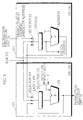
- Fig. 8 is a block diagram showing the construction of the processor of the second embodiment of the present invention.
- the difference with the processor 13 of the first embodiment shown in Fig. 1 lies in that the FIC 141 is replaced with a FIC 241 and the DIC 151 is replaced with a DIC 251.
- the processor 13 of the second embodiment is constructed such that a pointer to be stored in the DIC 251 is calculated by an instruction fetch unit 24 when a branch instruction is executed, while the pointer is calculated by the instruction execution unit 16 in the first embodiment. The following explanation focuses on this difference.
- Fig. 9 is a block diagram showing the detailed constructions of the FIC 241 and the DIC 251.
- the FIC 241 includes an adder 91, a latch 92, and a selector 93.
- a loop circuit that is made up of the adder 91, the latch 92, and the selector 93 composes a counter that is incremented by 4.
- the instruction fetch unit 24 fetches 4 bytes of code and increments the FIC 241.
- the selector 93 selects the output of the adder 91.
- the selector 93 selects a branch target address sent from the instruction execution unit 16.
- the selector 93 selects an address sent from the BAR 172.
- the selector 93 then outputs the selected address to the adder 91.
- the output of the latch 92 is sent to the external memory 11 as a fetch address.
- the DIC 251 includes an adder 101, a latch 102, and selectors 103 and 104.
- a loop circuit that is made up of the adder 101, the latch 102, and the selector 103 composes a counter that is incremented by the word length of a decoded instruction in each instruction decoding stage.
- the adder 101 When a non-branch instruction is decoded, the adder 101 adds the word length of the decoded instruction to the pointer in the latch 102 in the second half of the instruction decoding stage. When a branch instruction (except the high-speed loop instruction) that concerns the pointer in the DIC 251 is executed, the adder 101 adds "-4" to the pointer in the latch 102.
- the latch 102 stores a pointer that is the sum of a currently-decoded instruction address and the shift value 4. When initialized, the latch 102 stores "(the start address)+4" sent from the FIC 241.
- the selector 103 usually selects the word length of the decoded instruction which is provided by the instruction decoding unit 25. When an instruction such as a branch instruction with a relative address or a subroutine call instruction is executed, the selector 103 selects "-4" to adjust the pointer.
- the selector 104 selects the output of the adder 101.
- the selector 104 selects the output of the BAR 172.
- the selector 104 selects the output "(branch target address)+4" of the adder 91 in the FIC 241.
- Fig. 10 shows the operation contents of the same addressing instructions as Fig. 6, that is, the simple branch instruction “branch abs_adrs”, the subroutine call instruction “call abs_adrs”, the subroutine return instruction “ret”, and the simple branch instruction “branch rel_adrs”. Note that operations written above the dashed line are conducted in the instruction decoding stage, while operations written below the dashed line are conducted in the instruction execution stage.
- the instruction execution unit 16 When processing the simple branch instruction "branch abs_adrs", the instruction execution unit 16 stores the absolute address "abs_adrs" into the FIC 241 (Operation 1001), and the adder 91 in the instruction fetch unit 24 adds 4 to the address stored in the FIC 241, the sum then being stored into the DIC 251 (Operation 1002).
- the adder 91 in the FIC 241 is used to add the shift value 4 so as to calculate the pointer in the DIC 251.
- the instruction execution unit 16 When processing the subroutine call instruction "call abs_adrs", the instruction execution unit 16 stores the absolute address "abs_adrs" into the FIC 241 (Operation 1003).
- the adder 101 in the DIC 251 adds the instruction word length to the pointer (Operation 1004) and subtracts 4 from the addition result in the DIC 251.
- the instruction execution unit 16 pushes the subtracting result onto a stack (Operation 1005).
- the adder 91 in the FIC 241 adds 4 to the absolute address "abs_adrs" stored in the FIC 241, the sum then being stored into the DIC 251 (Operation 1006).
- the adder 101 in the DIC 251 is used to subtract the shift value 4 so as to calculate a return address that is pushed onto the stack, while the adder 91 in the FIC 241 is used to add the shift value 4 so as to calculate the pointer in the DIC 251.
- the instruction execution unit 16 When processing the subroutine return instruction "ret", the instruction execution unit 16 pops the return address, that is, an address of an instruction following the subroutine call instruction "call abs_adrs", from the stack and stores the return address into the FIC 241 (Operation 1007).
- the adder 91 in the FIC 241 adds 4 to the return address, the sum then being stored into the DIC 251 (Operation 1008).
- the adder 91 in the FIC 241 is used to add the shift value 4 so as to calculate the pointer in the DIC 251.
- the instruction execution unit 16 When processing the simple branch instruction "branch rel_adrs", the instruction execution unit 16 adds the relative address "rel_adrs" to a value obtained by the adder 101 subtracting 4 from the pointer in the DIC 251 and stores the sum into the FIC 241 (Operation 1009). Then the adder 91 adds 4 to the address stored in the FIC 241 and stores this sum into the DIC 251 (Operation 1010).
- the adder 101 in the DIC 251 is used to subtract the shift value 4 while the adder 91 in the FIC 241 is used to add the shift value 4.
- the addition of the shift value 4 in Operations 1002, 1006, 1008, and 1010 is performed by the adder 91 in the FIC 241, while the subtraction of the shift value 4 in Operations 1005 and 1009 is performed by the adder 101 in the DIC 251.
- Fig. 11 is a time chart showing the processing of the simple branch instruction "branch rel_adrs”.
- cycle T1 the adder 101 subtracts 4 from the pointer in the DIC 251.
- cycle T2 the instruction execution unit 16 adds the relative address "rel_adrs" to the subtracting result, so that a branch target address BA is calculated and stored into the FIC 241.
- the branch target address BA is outputted from the FIC 241 to the external memory 11 to fetch code (4 bytes) of a branch target instruction.
- the adder 91 adds 4 to the branch target address BA in FIC 241 in the second half of cycle T3.
- cycle T4 the sum obtained by the adder 91 is stored into the FIC 241 and the DIC 251.
- the processing unit of the processor is set at 32 bits in the above embodiments, the present invention is not limited to such. Accordingly, the processor may also process data in 16-or 64-bit units. Also, while the storage size of the BIR 171 is 4 bytes (32 bits) in the above embodiments, other storage sizes are applicable as long as at least one instruction can be fetched by the time the instruction decoder completes the decoding of branch target instruction code of that size within the cycle following the decoding of the high-speed loop instruction.
- the program used in the above embodiments is composed of instructions of variable word length
- the present invention may also be applied to instructions of fixed word length.
- the constructions of the DIC 151 and the selection unit 143 can further be simplified.
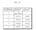
- the BIR 171 may also be constructed so that any byte in the 4 bytes of code stored in the BIR 171 may be set as the start of the code.
- Fig. 12 shows an example of such a modification of the queue 171a.
- the queue 171a shown in Fig. 4 is replaced with a 4-byte register 120 and selectors 121a-121d in the BIR 171.
- the selection logic of the selectors 121a-121d is shown in Fig. 13.
- the register 120 stores 4 bytes of code A, B, C, and D. If the number of valid bytes is 4, the selectors 121a-121d output the 4 bytes in order of "ABCD" to the DIB 152 via the selectors 143a-143d shown in Fig 4.
- the selectors 121a-121d output the 4 bytes in order of "BCDA".
- the selectors 143a-143d in the instruction fetch unit select the valid 3 bytes "BCD” and combine the valid 3 bytes "BCD” as high order bytes and 1 byte received from the FIB 142 as a low order byte to output 4 bytes of code to the DIB 152. The selection is performed in the same way when the number of valid bytes is 2 or 1.
- Fig. 12 enables the branch target instruction register to further increase its processing speed in comparison with when shifting is performed as shown in Fig. 4.
Landscapes
- Engineering & Computer Science (AREA)
- Software Systems (AREA)
- Theoretical Computer Science (AREA)
- Physics & Mathematics (AREA)
- General Engineering & Computer Science (AREA)
- General Physics & Mathematics (AREA)
- Advance Control (AREA)
- Executing Machine-Instructions (AREA)
Applications Claiming Priority (3)
| Application Number | Priority Date | Filing Date | Title |
|---|---|---|---|
| JP17455197 | 1997-06-30 | ||
| JP17455197 | 1997-06-30 | ||
| JP174551/97 | 1997-06-30 |
Publications (3)
| Publication Number | Publication Date |
|---|---|
| EP0889395A2 true EP0889395A2 (de) | 1999-01-07 |
| EP0889395A3 EP0889395A3 (de) | 1999-03-24 |
| EP0889395B1 EP0889395B1 (de) | 2001-09-12 |
Family
ID=15980543
Family Applications (1)
| Application Number | Title | Priority Date | Filing Date |
|---|---|---|---|
| EP98304886A Expired - Lifetime EP0889395B1 (de) | 1997-06-30 | 1998-06-22 | Reduzierung der Verzweigungsfehler durch einen Pipeline-Prozessor mit einer Schaltung mit geringer Schaltungsgrösse |
Country Status (6)
| Country | Link |
|---|---|
| US (1) | US6189092B1 (de) |
| EP (1) | EP0889395B1 (de) |
| KR (1) | KR100510030B1 (de) |
| CN (1) | CN1105350C (de) |
| DE (1) | DE69801617T2 (de) |
| TW (1) | TW377422B (de) |
Cited By (2)
| Publication number | Priority date | Publication date | Assignee | Title |
|---|---|---|---|---|
| WO2002099632A1 (en) * | 2001-06-06 | 2002-12-12 | Koninklijke Philips Electronics N.V. | Electronic device and method for processing compressed program code |
| EP1868081A4 (de) * | 2005-04-08 | 2008-08-13 | Matsushita Electric Industrial Co Ltd | Prozessor |
Families Citing this family (11)
| Publication number | Priority date | Publication date | Assignee | Title |
|---|---|---|---|---|
| US7032100B1 (en) * | 1999-12-17 | 2006-04-18 | Koninklijke Philips Electronics N.V. | Simple algorithmic cryptography engine |
| US6728872B1 (en) | 2000-02-04 | 2004-04-27 | International Business Machines Corporation | Method and apparatus for verifying that instructions are pipelined in correct architectural sequence |
| KR100360888B1 (ko) * | 2000-08-01 | 2002-11-13 | 엘지전자 주식회사 | 피디피 티브이 모듈의 단자전압 자동 조정장치 |
| US7185177B2 (en) * | 2002-08-26 | 2007-02-27 | Gerald George Pechanek | Methods and apparatus for meta-architecture defined programmable instruction fetch functions supporting assembled variable length instruction processors |
| US7020769B2 (en) * | 2003-09-30 | 2006-03-28 | Starcore, Llc | Method and system for processing a loop of instructions |
| US7412587B2 (en) * | 2004-02-16 | 2008-08-12 | Matsushita Electric Industrial Co., Ltd. | Parallel operation processor utilizing SIMD data transfers |
| JP2006309337A (ja) * | 2005-04-26 | 2006-11-09 | Toshiba Corp | プロセッサ及びプロセッサの命令バッファ動作方法 |
| US9507600B2 (en) * | 2014-01-27 | 2016-11-29 | Texas Instruments Deutschland Gmbh | Processor loop buffer |
| CN104699463B (zh) * | 2015-03-20 | 2017-05-17 | 浪潮集团有限公司 | 一种低功耗流水线的实现方法 |
| GB2548604B (en) * | 2016-03-23 | 2018-03-21 | Advanced Risc Mach Ltd | Branch instruction |
| CN115314161A (zh) * | 2022-08-05 | 2022-11-08 | 北京天融信网络安全技术有限公司 | 报文处理方法、装置、电子设备及存储介质 |
Family Cites Families (11)
| Publication number | Priority date | Publication date | Assignee | Title |
|---|---|---|---|---|
| US4463422A (en) | 1982-07-12 | 1984-07-31 | Csp, Inc. | Method of processing an iterative program loop |
| JPS6051948A (ja) | 1983-08-31 | 1985-03-23 | Hitachi Ltd | 情報処理装置 |
| US4714994A (en) | 1985-04-30 | 1987-12-22 | International Business Machines Corp. | Instruction prefetch buffer control |
| JP2708405B2 (ja) | 1986-03-03 | 1998-02-04 | 株式会社日立製作所 | コンパイラにおけるループ展開方法 |
| US4933837A (en) | 1986-12-01 | 1990-06-12 | Advanced Micro Devices, Inc. | Methods and apparatus for optimizing instruction processing in computer systems employing a combination of instruction cache and high speed consecutive transfer memories |
| US5522053A (en) * | 1988-02-23 | 1996-05-28 | Mitsubishi Denki Kabushiki Kaisha | Branch target and next instruction address calculation in a pipeline processor |
| JP3102027B2 (ja) | 1990-11-20 | 2000-10-23 | 日本電気株式会社 | ループ制御のネスティング管理機構 |
| US5450585A (en) | 1991-05-15 | 1995-09-12 | International Business Machines Corporation | Compiler with delayed conditional branching |
| JP2761688B2 (ja) * | 1992-02-07 | 1998-06-04 | 三菱電機株式会社 | データ処理装置 |
| GB2285154B (en) | 1993-12-24 | 1998-04-01 | Advanced Risc Mach Ltd | Branch cache |
| JP2987311B2 (ja) * | 1995-05-12 | 1999-12-06 | 松下電器産業株式会社 | プロセッサ及び翻訳装置 |
-
1998
- 1998-06-18 US US09/099,299 patent/US6189092B1/en not_active Expired - Lifetime
- 1998-06-22 DE DE69801617T patent/DE69801617T2/de not_active Expired - Lifetime
- 1998-06-22 EP EP98304886A patent/EP0889395B1/de not_active Expired - Lifetime
- 1998-06-29 CN CN98103178A patent/CN1105350C/zh not_active Expired - Lifetime
- 1998-06-29 TW TW087110470A patent/TW377422B/zh active
- 1998-06-30 KR KR10-1998-0025495A patent/KR100510030B1/ko not_active Expired - Lifetime
Cited By (3)
| Publication number | Priority date | Publication date | Assignee | Title |
|---|---|---|---|---|
| WO2002099632A1 (en) * | 2001-06-06 | 2002-12-12 | Koninklijke Philips Electronics N.V. | Electronic device and method for processing compressed program code |
| FR2825810A1 (fr) * | 2001-06-06 | 2002-12-13 | Koninkl Philips Electronics Nv | Dispositif electronique a processeur pipeline utilisant un compactage de code et procede de gestion d'un tel processeur |
| EP1868081A4 (de) * | 2005-04-08 | 2008-08-13 | Matsushita Electric Industrial Co Ltd | Prozessor |
Also Published As
| Publication number | Publication date |
|---|---|
| KR19990007479A (ko) | 1999-01-25 |
| CN1105350C (zh) | 2003-04-09 |
| US6189092B1 (en) | 2001-02-13 |
| DE69801617D1 (de) | 2001-10-18 |
| CN1206144A (zh) | 1999-01-27 |
| DE69801617T2 (de) | 2002-02-07 |
| EP0889395B1 (de) | 2001-09-12 |
| TW377422B (en) | 1999-12-21 |
| EP0889395A3 (de) | 1999-03-24 |
| KR100510030B1 (ko) | 2005-12-21 |
Similar Documents
| Publication | Publication Date | Title |
|---|---|---|
| US5101341A (en) | Pipelined system for reducing instruction access time by accumulating predecoded instruction bits a FIFO | |
| US5881260A (en) | Method and apparatus for sequencing and decoding variable length instructions with an instruction boundary marker within each instruction | |
| US7139902B2 (en) | Implementation of an efficient instruction fetch pipeline utilizing a trace cache | |
| EP0772821B1 (de) | Markierter vorausladungsabstand-und befehlsdekoder von variabler länge, befehlssätze und ihre verwendungsweise | |
| US5996057A (en) | Data processing system and method of permutation with replication within a vector register file | |
| US5828875A (en) | Unroll of instructions in a micro-controller | |
| US6334176B1 (en) | Method and apparatus for generating an alignment control vector | |
| US5727194A (en) | Repeat-bit based, compact system and method for implementing zero-overhead loops | |
| US5390307A (en) | Apparatus for a multi-data store or load instruction for transferring multiple contiguous storage locations in one transfer operation | |
| US4399507A (en) | Instruction address stack in the data memory of an instruction-pipelined processor | |
| US5608886A (en) | Block-based branch prediction using a target finder array storing target sub-addresses | |
| KR100227276B1 (ko) | 단일 사이클 마이크로 명령을 이용한 명령 스케줄링 방법 및 프로세서 | |
| US5131086A (en) | Method and system for executing pipelined three operand construct | |
| EP0889395B1 (de) | Reduzierung der Verzweigungsfehler durch einen Pipeline-Prozessor mit einer Schaltung mit geringer Schaltungsgrösse | |
| US12455745B2 (en) | Processor subroutine cache | |
| US7159098B2 (en) | Selecting next instruction line buffer stage based on current instruction line boundary wraparound and branch target in buffer indicator | |
| JP2816248B2 (ja) | データプロセッサ | |
| KR19980069855A (ko) | 넓은 데이터 폭의 프로세서에서 다기능 데이타 정렬기 | |
| JP2006185462A (ja) | 高データ密度のriscプロセッサ | |
| JPH0816391A (ja) | コンピュータシステム、命令ビット長圧縮方法、命令発生方法、及びコンピュータシステム動作方法 | |
| JPH05143336A (ja) | デジタル・コンピユータ及び分岐命令実行方法 | |
| US11816485B2 (en) | Nested loop control | |
| US11972236B1 (en) | Nested loop control | |
| US5459847A (en) | Program counter mechanism having selector for selecting up-to-date instruction prefetch address based upon carry signal of adder which adds instruction size and LSB portion of address register | |
| US5542060A (en) | Data processor including a decoding unit for decomposing a multifunctional data transfer instruction into a plurality of control codes |
Legal Events
| Date | Code | Title | Description |
|---|---|---|---|
| PUAI | Public reference made under article 153(3) epc to a published international application that has entered the european phase |
Free format text: ORIGINAL CODE: 0009012 |
|
| AK | Designated contracting states |
Kind code of ref document: A2 Designated state(s): DE FR GB NL |
|
| AX | Request for extension of the european patent |
Free format text: AL;LT;LV;MK;RO;SI |
|
| PUAL | Search report despatched |
Free format text: ORIGINAL CODE: 0009013 |
|
| AK | Designated contracting states |
Kind code of ref document: A3 Designated state(s): AT BE CH CY DE DK ES FI FR GB GR IE IT LI LU MC NL PT SE |
|
| AX | Request for extension of the european patent |
Free format text: AL;LT;LV;MK;RO;SI |
|
| 17P | Request for examination filed |
Effective date: 19990507 |
|
| AKX | Designation fees paid |
Free format text: DE FR GB NL |
|
| 17Q | First examination report despatched |
Effective date: 19991125 |
|
| GRAG | Despatch of communication of intention to grant |
Free format text: ORIGINAL CODE: EPIDOS AGRA |
|
| GRAG | Despatch of communication of intention to grant |
Free format text: ORIGINAL CODE: EPIDOS AGRA |
|
| GRAH | Despatch of communication of intention to grant a patent |
Free format text: ORIGINAL CODE: EPIDOS IGRA |
|
| GRAH | Despatch of communication of intention to grant a patent |
Free format text: ORIGINAL CODE: EPIDOS IGRA |
|
| GRAA | (expected) grant |
Free format text: ORIGINAL CODE: 0009210 |
|
| AK | Designated contracting states |
Kind code of ref document: B1 Designated state(s): DE FR GB NL |
|
| REF | Corresponds to: |
Ref document number: 69801617 Country of ref document: DE Date of ref document: 20011018 |
|
| REG | Reference to a national code |
Ref country code: GB Ref legal event code: IF02 |
|
| ET | Fr: translation filed | ||
| PLBE | No opposition filed within time limit |
Free format text: ORIGINAL CODE: 0009261 |
|
| STAA | Information on the status of an ep patent application or granted ep patent |
Free format text: STATUS: NO OPPOSITION FILED WITHIN TIME LIMIT |
|
| 26N | No opposition filed | ||
| REG | Reference to a national code |
Ref country code: FR Ref legal event code: CD Owner name: PANASONIC CORPORATION, JP Effective date: 20150120 |
|
| REG | Reference to a national code |
Ref country code: DE Ref legal event code: R082 Ref document number: 69801617 Country of ref document: DE Representative=s name: GRUENECKER PATENT- UND RECHTSANWAELTE PARTG MB, DE |
|
| REG | Reference to a national code |
Ref country code: NL Ref legal event code: TD Effective date: 20150323 |
|
| REG | Reference to a national code |
Ref country code: DE Ref legal event code: R082 Ref document number: 69801617 Country of ref document: DE Representative=s name: GRUENECKER PATENT- UND RECHTSANWAELTE PARTG MB, DE Effective date: 20150316 Ref country code: DE Ref legal event code: R081 Ref document number: 69801617 Country of ref document: DE Owner name: GODO KAISHA IP BRIDGE 1, JP Free format text: FORMER OWNER: PANASONIC CORPORATION, KADOMA-SHI, OSAKA, JP Effective date: 20150316 |
|
| REG | Reference to a national code |
Ref country code: FR Ref legal event code: TP Owner name: GODO KAISHA IP BRIDGE 1, JP Effective date: 20150422 |
|
| REG | Reference to a national code |
Ref country code: NL Ref legal event code: TD Effective date: 20150610 Ref country code: NL Ref legal event code: SD Effective date: 20150610 |
|
| REG | Reference to a national code |
Ref country code: GB Ref legal event code: 732E Free format text: REGISTERED BETWEEN 20150611 AND 20150617 |
|
| REG | Reference to a national code |
Ref country code: FR Ref legal event code: PLFP Year of fee payment: 19 |
|
| REG | Reference to a national code |
Ref country code: FR Ref legal event code: PLFP Year of fee payment: 20 |
|
| PGFP | Annual fee paid to national office [announced via postgrant information from national office to epo] |
Ref country code: NL Payment date: 20170512 Year of fee payment: 20 |
|
| PGFP | Annual fee paid to national office [announced via postgrant information from national office to epo] |
Ref country code: DE Payment date: 20170613 Year of fee payment: 20 Ref country code: GB Payment date: 20170621 Year of fee payment: 20 Ref country code: FR Payment date: 20170511 Year of fee payment: 20 |
|
| REG | Reference to a national code |
Ref country code: DE Ref legal event code: R071 Ref document number: 69801617 Country of ref document: DE |
|
| REG | Reference to a national code |
Ref country code: NL Ref legal event code: MK Effective date: 20180621 |
|
| REG | Reference to a national code |
Ref country code: GB Ref legal event code: PE20 Expiry date: 20180621 |
|
| PG25 | Lapsed in a contracting state [announced via postgrant information from national office to epo] |
Ref country code: GB Free format text: LAPSE BECAUSE OF EXPIRATION OF PROTECTION Effective date: 20180621 |