EP0889537B1 - Hochtemperatur-Brennstoffzellenanlage - Google Patents
Hochtemperatur-Brennstoffzellenanlage Download PDFInfo
- Publication number
- EP0889537B1 EP0889537B1 EP97111206A EP97111206A EP0889537B1 EP 0889537 B1 EP0889537 B1 EP 0889537B1 EP 97111206 A EP97111206 A EP 97111206A EP 97111206 A EP97111206 A EP 97111206A EP 0889537 B1 EP0889537 B1 EP 0889537B1
- Authority
- EP
- European Patent Office
- Prior art keywords
- fuel cell
- temperature fuel
- wall
- cell stack
- waste gas
- Prior art date
- Legal status (The legal status is an assumption and is not a legal conclusion. Google has not performed a legal analysis and makes no representation as to the accuracy of the status listed.)
- Expired - Lifetime
Links
Images

Classifications
-
- H—ELECTRICITY
- H01—ELECTRIC ELEMENTS
- H01M—PROCESSES OR MEANS, e.g. BATTERIES, FOR THE DIRECT CONVERSION OF CHEMICAL ENERGY INTO ELECTRICAL ENERGY
- H01M8/00—Fuel cells; Manufacture thereof
- H01M8/24—Grouping of fuel cells, e.g. stacking of fuel cells
- H01M8/2465—Details of groupings of fuel cells
- H01M8/247—Arrangements for tightening a stack, for accommodation of a stack in a tank or for assembling different tanks
-
- H—ELECTRICITY
- H01—ELECTRIC ELEMENTS
- H01M—PROCESSES OR MEANS, e.g. BATTERIES, FOR THE DIRECT CONVERSION OF CHEMICAL ENERGY INTO ELECTRICAL ENERGY
- H01M8/00—Fuel cells; Manufacture thereof
- H01M8/10—Fuel cells with solid electrolytes
- H01M8/12—Fuel cells with solid electrolytes operating at high temperature, e.g. with stabilised ZrO2 electrolyte
- H01M2008/1293—Fuel cells with solid oxide electrolytes
-
- H—ELECTRICITY
- H01—ELECTRIC ELEMENTS
- H01M—PROCESSES OR MEANS, e.g. BATTERIES, FOR THE DIRECT CONVERSION OF CHEMICAL ENERGY INTO ELECTRICAL ENERGY
- H01M8/00—Fuel cells; Manufacture thereof
- H01M8/14—Fuel cells with fused electrolytes
- H01M2008/147—Fuel cells with molten carbonates
-
- H—ELECTRICITY
- H01—ELECTRIC ELEMENTS
- H01M—PROCESSES OR MEANS, e.g. BATTERIES, FOR THE DIRECT CONVERSION OF CHEMICAL ENERGY INTO ELECTRICAL ENERGY
- H01M2300/00—Electrolytes
- H01M2300/0017—Non-aqueous electrolytes
- H01M2300/0048—Molten electrolytes used at high temperature
- H01M2300/0051—Carbonates
-
- H—ELECTRICITY
- H01—ELECTRIC ELEMENTS
- H01M—PROCESSES OR MEANS, e.g. BATTERIES, FOR THE DIRECT CONVERSION OF CHEMICAL ENERGY INTO ELECTRICAL ENERGY
- H01M2300/00—Electrolytes
- H01M2300/0017—Non-aqueous electrolytes
- H01M2300/0065—Solid electrolytes
- H01M2300/0068—Solid electrolytes inorganic
- H01M2300/0071—Oxides
- H01M2300/0074—Ion conductive at high temperature
-
- H—ELECTRICITY
- H01—ELECTRIC ELEMENTS
- H01M—PROCESSES OR MEANS, e.g. BATTERIES, FOR THE DIRECT CONVERSION OF CHEMICAL ENERGY INTO ELECTRICAL ENERGY
- H01M8/00—Fuel cells; Manufacture thereof
- H01M8/04—Auxiliary arrangements, e.g. for control of pressure or for circulation of fluids
- H01M8/04007—Auxiliary arrangements, e.g. for control of pressure or for circulation of fluids related to heat exchange
- H01M8/04014—Heat exchange using gaseous fluids; Heat exchange by combustion of reactants
-
- H—ELECTRICITY
- H01—ELECTRIC ELEMENTS
- H01M—PROCESSES OR MEANS, e.g. BATTERIES, FOR THE DIRECT CONVERSION OF CHEMICAL ENERGY INTO ELECTRICAL ENERGY
- H01M8/00—Fuel cells; Manufacture thereof
- H01M8/04—Auxiliary arrangements, e.g. for control of pressure or for circulation of fluids
- H01M8/04007—Auxiliary arrangements, e.g. for control of pressure or for circulation of fluids related to heat exchange
- H01M8/04014—Heat exchange using gaseous fluids; Heat exchange by combustion of reactants
- H01M8/04022—Heating by combustion
-
- Y—GENERAL TAGGING OF NEW TECHNOLOGICAL DEVELOPMENTS; GENERAL TAGGING OF CROSS-SECTIONAL TECHNOLOGIES SPANNING OVER SEVERAL SECTIONS OF THE IPC; TECHNICAL SUBJECTS COVERED BY FORMER USPC CROSS-REFERENCE ART COLLECTIONS [XRACs] AND DIGESTS
- Y02—TECHNOLOGIES OR APPLICATIONS FOR MITIGATION OR ADAPTATION AGAINST CLIMATE CHANGE
- Y02E—REDUCTION OF GREENHOUSE GAS [GHG] EMISSIONS, RELATED TO ENERGY GENERATION, TRANSMISSION OR DISTRIBUTION
- Y02E60/00—Enabling technologies; Technologies with a potential or indirect contribution to GHG emissions mitigation
- Y02E60/30—Hydrogen technology
- Y02E60/50—Fuel cells
Definitions
- the invention relates to a high-temperature fuel cell system.
- the high temperature fuel cell system contains a high temperature fuel cell stack with a number of high temperature fuel cells (for example over 50 high temperature fuel cells) .
- the high temperature fuel cell stack has an operating temperature of over 600 ° C and is subject to high requirements regarding the heating of its necessary for operation Resources. To do this, it must be ensured that the assembling the high temperature fuel cell system Components are appropriately thermally insulated (i.e. that if possible little thermal energy from the high-temperature fuel cell system is released to the environment). Besides, should that when operating the high temperature fuel cell system waste heat generated for heating the equipment of the High temperature fuel cell stacks are used.
- DE 195 48 297 A1 describes a fuel cell arrangement known in which a fuel cell stack from a gas space is surrounded. A heat exchanger is arranged in the gas space the fuel gas supplied to the fuel cell stack is preheated. The heating takes place through heat exchange with an exhaust air circulated in the gas space.
- the fuel gas is routed here via a pipe system. For circulating the exhaust air and for supplying fresh air to the fuel cell stack are complex structures on the fuel cell stack intended.
- a fuel cell system is disclosed in DE 43 39 405 C1 remove, consisting of a fuel cell stack this surrounding cylindrical housing with intermediate Exhaust chamber.
- the housing has gas supply and discharge connections on.
- the fuel cell stack is in held the housing.
- WO 96/20506 also shows the air in one Circulate the gas space between the fuel cell stack and the housing and to arrange a heat exchanger in this gas space.
- the individual internals and in particular the fuel cell stack for revision work is not without more accessible.
- the object of the invention is a high-temperature fuel cell system state the equipment with good Efficiency can be warmed up by the exhaust gases and yet a compact structure is guaranteed.
- a high temperature fuel cell system with at least is according to a high temperature fuel cell stack the invention of the high temperature fuel cell stack in a predetermined distance at least partially from an outer wall surround. Between the high temperature fuel cell stack and the outer wall is at least a first exhaust space formed, through which an exhaust gas from the high temperature fuel cell stack is derived to the outside. in the The first exhaust gas chamber is a heat exchanger for an operating medium of the high-temperature fuel cell stack arranged. At the same time is between the high temperature fuel cell stack and the outer wall arranged at least one partition, the separates the first exhaust gas space from a second exhaust gas space.
- This high-temperature fuel cell system surrounds the two exhaust gas chambers at least partially the high-temperature fuel cell stack.
- the exhaust gases are without additional Drain lines from the high-temperature fuel cell stack fed directly into the respective exhaust gas chamber.
- the high-temperature fuel cell stack at a predetermined distance at least partially from one Partition be surrounded.
- the first exhaust space is then between the partition and the outer wall.
- the partition serves next to the outer wall (if, for example, on your Mirrored inside and / or in another way with a thermal insulating lining is provided) as an additional Thermal insulation to prevent the loss of thermal energy in the To keep high temperature fuel cell stacks as low as possible.
- the outer wall preferably has a thermally insulating one Lining, which is preferably attached to the inside is where it can also be used as a bracket and / or sealing material for the Partitions can serve. Because of this thermal insulation ensures that the energy of the waste heat of the high temperature fuel cell stack largely within the high temperature fuel cell system is withheld and for Heating the equipment is used. In addition, at the same time reduces the thermal load on the outer wall.
- the cross sections of the outer and intermediate wall be circular. This cross-sectional shape of the walls proves proved to be particularly favorable for thermal reasons.
- the heat exchangers are included Spacers attached to the outer wall. This ensures that largely the entire surface of the heat exchanger is available to heat the equipment.
- the high temperature fuel cell stack is preferably arranged on a base plate, the base plate with Can be positioned using guide claws attached to the outer wall is.
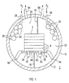
- the high temperature fuel cell system 2 contains a high temperature fuel cell stack 4, which is made up of a plurality of high-temperature fuel cells 6 composed.
- the high temperature fuel cell stack 4 is arranged on a base plate 8.
- the base plate 8 can already be part of the high-temperature fuel cell stack 4.
- the high temperature fuel cell stack 4 is in a predetermined Distance surrounded by an outer wall 10 on her Provided on the inside with a heat-insulating layer 12 is.
- the outer wall 10 has in this embodiment a circular cross section and practically forms a cylindrical Pipe at both ends of a (not shown) Cover plate is closed.
- the high temperature fuel cell system 2 is about 1 m high (the height corresponds to the diameter of the circular cross section) and has a length of approximately 2.5 m. No further in one illustrated embodiment, the outer wall has a rectangular cross section.
- the high temperature fuel cell stack can then directly on the floor, i.e. on the Bottom portion of the right-angled wall be (the high temperature fuel cell stack has at rectangular cross-section no longer on all sides Distance from the outer wall).
- a partition 16 is provided by the Top of the high temperature fuel cell stack 4 to the outer wall 10 (in the upper area).
- Another partition 18 is between the base plate 8 of the high temperature fuel cell stack 4 and the outer wall 10, the partition 18 from the underside of the base plate 8 to the outer wall 10 (in the lower area).
- the two Partitions 16 and 18 divide that by the outer wall 10 and the high temperature fuel cell stack 4 limited interior into a first exhaust space 20 and a second exhaust space 22 on.
- a heat exchanger 24 (which, for example, consists of a plurality of tubular sections running side by side, which are preferably formed like a helix) for an operating medium (for example hydrogen (H 2 )) of the high-temperature fuel cell stack 4 is arranged.
- the heat exchanger 24 is fastened to the outer wall 10 with spacers 26 and extends approximately over the entire length of the high-temperature fuel cell system 2.
- the heat exchanger 24 is supplied with the operating medium via a feed 28.
- the operating medium is fed from the heat exchanger 24 to a distributor line 32 arranged below the high-temperature fuel cell stack 4 via a line (not shown further).
- the operating medium is fed from the distribution line 32 into the high-temperature fuel cell stack 4 via a feed 34.
- a further heat exchanger 25 for a further operating medium (here oxygen (O 2 )) of the high-temperature fuel cell stack 4 is arranged in the second exhaust gas chamber 22.
- the heat exchanger 25 is fastened to the outer wall 10 with spacers 26 and extends approximately over the entire length of the high-temperature fuel cell system 2.
- the heat exchanger 25 is supplied with the oxygen (O 2 ) via a feed 29.
- the operating medium is fed from the heat exchanger 25 to a distributor line 33 arranged below the high-temperature fuel cell stack 4 via a line (not shown further).
- the operating medium is fed from the distribution line 33 into the high-temperature fuel cell stack 4 via a feed 35. If a plurality of high-temperature fuel cell stacks 4 are arranged one behind the other on the base plate 8 in the longitudinal direction of the high-temperature fuel cell system 2, these can likewise be supplied with the operating resources via the distributor line 33 or via the distributor line 32.
- the hydrogen-containing and the oxygen-containing exhaust gas of the high-temperature fuel cell stack 4 is passed through the bushings 60 and 62 into the first and second exhaust gas spaces 20, 22.
- the hot exhaust gases (with a temperature of at least 600 ° C.) of the high-temperature fuel cell stack 4 flow around the heat exchangers 24, 25 and the distribution lines 32, 33 and heat the operating materials (namely the hydrogen (H 2 ) im Heat exchanger 24 and in the distributor line 32 or the oxygen (O 2 ) in the heat exchanger 25 and in the distributor line 33).
- the exhaust gases (after they have released a portion of their thermal energy) are removed from the high-temperature fuel cell system 2 via the outlets 64, 66 arranged in the upper region of the outer wall 10.
- Heat exchangers are used to heat the equipment 24.25 (e.g. pipelines from a heat-conducting Material) used to provide the equipment for the high temperature fuel cell stack 4 are provided (and not separately provided for heating Need to become). There won't be any additional Premises needed for the heating process.
- equipment 24.25 e.g. pipelines from a heat-conducting Material
- the base plate 8 (with the high-temperature fuel cell stack arranged on it 4) is made for easy removal the high-temperature fuel cell system 2 in four guide claws 50 mounted like rails, the lower area are attached to the inside of the outer wall 10.
- the Guide brackets 50 are the only thermal contact (thermal bridges) of the high-temperature fuel cell stack 4 with the outer wall 10.
- the high-temperature fuel cell system 2 also guarantees good efficiency heating the equipment, whereby nevertheless a compact structure is given.
- the high-temperature fuel cell system 2 shown in FIG. 2 has, in addition to FIG. 1, an intermediate wall 38 which partially surrounds the high-temperature fuel cell stack 4 at a predetermined distance (together with the base plate 8, it completely surrounds it).
- the intermediate wall 38 is circular and is provided on its inside with a thermally insulating layer 52.
- the inner space 70 formed between the high-temperature fuel cell stack 4 and the intermediate wall 38 contains a protective gas (for example nitrogen (N 2 )).
- the first and the second Exhaust gas space 20, 22 between the intermediate wall 38 and the outer wall 10 formed, these through the two partitions 40.42 are separated.
- Circular openings 44 are provided in the partition 40, through which an exchange of hydrogen-containing and oxygen-containing exhaust gas between the first and the second exhaust gas space 20, 22.
- the two exhaust gases react in the vicinity of the openings 44 of the partition 40 with each other and put more heat energy (in addition to the already in the exhaust gases containing thermal energy) for heating of resources free.
Landscapes
- Fuel Cell (AREA)
- Life Sciences & Earth Sciences (AREA)
- Engineering & Computer Science (AREA)
- Manufacturing & Machinery (AREA)
- Sustainable Development (AREA)
- Sustainable Energy (AREA)
- Chemical & Material Sciences (AREA)
- Chemical Kinetics & Catalysis (AREA)
- Electrochemistry (AREA)
- General Chemical & Material Sciences (AREA)
Priority Applications (4)
| Application Number | Priority Date | Filing Date | Title |
|---|---|---|---|
| DE59703472T DE59703472D1 (de) | 1997-07-03 | 1997-07-03 | Hochtemperatur-Brennstoffzellenanlage |
| DK97111206T DK0889537T3 (da) | 1997-07-03 | 1997-07-03 | Højtemperatur-brændstofcelleanlæg |
| EP97111206A EP0889537B1 (de) | 1997-07-03 | 1997-07-03 | Hochtemperatur-Brennstoffzellenanlage |
| AT97111206T ATE200943T1 (de) | 1997-07-03 | 1997-07-03 | Hochtemperatur-brennstoffzellenanlage |
Applications Claiming Priority (1)
| Application Number | Priority Date | Filing Date | Title |
|---|---|---|---|
| EP97111206A EP0889537B1 (de) | 1997-07-03 | 1997-07-03 | Hochtemperatur-Brennstoffzellenanlage |
Publications (2)
| Publication Number | Publication Date |
|---|---|
| EP0889537A1 EP0889537A1 (de) | 1999-01-07 |
| EP0889537B1 true EP0889537B1 (de) | 2001-05-02 |
Family
ID=8227006
Family Applications (1)
| Application Number | Title | Priority Date | Filing Date |
|---|---|---|---|
| EP97111206A Expired - Lifetime EP0889537B1 (de) | 1997-07-03 | 1997-07-03 | Hochtemperatur-Brennstoffzellenanlage |
Country Status (4)
| Country | Link |
|---|---|
| EP (1) | EP0889537B1 (da) |
| AT (1) | ATE200943T1 (da) |
| DE (1) | DE59703472D1 (da) |
| DK (1) | DK0889537T3 (da) |
Cited By (1)
| Publication number | Priority date | Publication date | Assignee | Title |
|---|---|---|---|---|
| US7226681B2 (en) | 2002-06-21 | 2007-06-05 | Versa Power Systems, Ltd. | Fuel cell insulating heat exchanger |
Families Citing this family (1)
| Publication number | Priority date | Publication date | Assignee | Title |
|---|---|---|---|---|
| KR102811674B1 (ko) | 2019-12-20 | 2025-05-22 | 세인트-고바인 세라믹스 앤드 플라스틱스, 인크. | 전기화학 장치 및 열 교환기를 포함하는 장치 |
Family Cites Families (14)
| Publication number | Priority date | Publication date | Assignee | Title |
|---|---|---|---|---|
| US3146131A (en) * | 1961-03-20 | 1964-08-25 | Inst Gas Technology | Appliance for production of direct electric current |
| US3718506A (en) * | 1971-02-22 | 1973-02-27 | Bbc Brown Boveri & Cie | Fuel cell system for reacting hydrocarbons |
| JPS60254568A (ja) * | 1984-05-30 | 1985-12-16 | Fuji Electric Corp Res & Dev Ltd | 燃料電池 |
| JPS62283570A (ja) * | 1986-05-31 | 1987-12-09 | Mitsubishi Heavy Ind Ltd | 高温固体電解質型燃料電池 |
| EP0374636A1 (de) * | 1988-12-20 | 1990-06-27 | Asea Brown Boveri Ag | Verfahren zur Umwandlung von in einem Stoff als chemisches Potential vorliegender Energie in elektrische Energie basierend auf einem elektrochemischen Hochtemperaturprozess |
| JPH0547409A (ja) * | 1991-08-20 | 1993-02-26 | Fuji Electric Co Ltd | 固体電解質型燃料電池 |
| JP3571060B2 (ja) * | 1992-09-21 | 2004-09-29 | 東燃ゼネラル石油株式会社 | 高温型燃料電池 |
| US5340664A (en) * | 1993-09-29 | 1994-08-23 | Ceramatec, Inc. | Thermally integrated heat exchange system for solid oxide electrolyte systems |
| WO1995010126A1 (en) * | 1993-10-06 | 1995-04-13 | Ceramatec, Inc. | Integrated reformer/cpn sofc stack module design |
| DE4339405C1 (de) * | 1993-11-18 | 1995-01-12 | Mtu Friedrichshafen Gmbh | Gasdichtes Gehäuse für Brennstoffzellenstapel mit Montage des Brennstoffzellenstapels |
| DE4446841A1 (de) * | 1994-12-27 | 1996-07-04 | Mtu Friedrichshafen Gmbh | Brennstoffzellenmodul |
| DE19548297C2 (de) * | 1995-12-22 | 2001-03-08 | Mtu Friedrichshafen Gmbh | Brennstoffzellenanordnung und Verfahren zum Betreiben einer Solchen |
| US5612149A (en) * | 1996-01-02 | 1997-03-18 | Ceramatec, Inc. | Fuel cell column heat exchanger mated module |
| DE19606665C2 (de) * | 1996-02-23 | 2003-02-27 | Aeg Energietechnik Gmbh | Anlage zur Erzeugung elektrischer Energie mit Festoxidbrennstoffzellen |
-
1997
- 1997-07-03 DE DE59703472T patent/DE59703472D1/de not_active Expired - Fee Related
- 1997-07-03 EP EP97111206A patent/EP0889537B1/de not_active Expired - Lifetime
- 1997-07-03 DK DK97111206T patent/DK0889537T3/da active
- 1997-07-03 AT AT97111206T patent/ATE200943T1/de not_active IP Right Cessation
Cited By (1)
| Publication number | Priority date | Publication date | Assignee | Title |
|---|---|---|---|---|
| US7226681B2 (en) | 2002-06-21 | 2007-06-05 | Versa Power Systems, Ltd. | Fuel cell insulating heat exchanger |
Also Published As
| Publication number | Publication date |
|---|---|
| ATE200943T1 (de) | 2001-05-15 |
| DK0889537T3 (da) | 2001-08-20 |
| EP0889537A1 (de) | 1999-01-07 |
| DE59703472D1 (de) | 2001-06-07 |
Similar Documents
| Publication | Publication Date | Title |
|---|---|---|
| DE69103455T2 (de) | Energiegewinnungssystem mit flachen Brennstoffzellen aus festen Elektrolyten. | |
| DE10041532A1 (de) | Brennstoffzellenstapel | |
| DE10040792C2 (de) | Polymerelektrolytmembran-Brennstoffzellensystem mit Kühlmedium-Verteilungsraum und-Sammelraum und mit Kühlung durch fluide Medien | |
| DE2824628C2 (de) | Scheuerleistenheizkörper | |
| EP0771477A1 (de) | Verfahren und vorrichtung zum betreiben einer brennstoffzellenanordnung | |
| DE4234093A1 (de) | Bauelement zum Einbau in eine verfahrenstechnische Einrichtung | |
| WO2010054647A2 (de) | Brennstoffzelle ohne bipolarplatten | |
| DE102019108160A1 (de) | Bipolarplatte zur Verwendung in einem Brennstoffzellenstapel | |
| EP3476000B1 (de) | Vorrichtung zur energieumwandlung, insbesondere brennstoffzelle oder elektrolyseur | |
| EP0889537B1 (de) | Hochtemperatur-Brennstoffzellenanlage | |
| WO2006097298A1 (de) | Reformer-brennstoffzellen-system mit externem brenner | |
| DE19606665C2 (de) | Anlage zur Erzeugung elektrischer Energie mit Festoxidbrennstoffzellen | |
| DE102018125283B4 (de) | Batteriemodul | |
| EP1205000B1 (de) | Kühlsystem für brennstoffzellen und verfahren zum betreiben desselben | |
| WO1994022179A1 (de) | Anordnung zum anschliessen von stapeln von hochtemperaturbrennstoffzellen | |
| DE69209828T2 (de) | Verteilung von kühlluft in schaltschränken | |
| WO2007000218A2 (de) | Bipolarplatte, verfahren zur herstellung einer bipolarplatte und brennstoffzellenblock-anordnung | |
| DE102019110195B4 (de) | Temperierungsvorrichtung | |
| EP0870343A1 (de) | Brennstoffzelleneinrichtung mit röhrenförmigen hochtemperatur-brennstoffzellen | |
| EP1180496B1 (de) | Vorrichtung zur Zuführung von Edukten zu parallelen Räumen | |
| EP1994594B1 (de) | Brennstoffzellenanordnung | |
| DE112009003594T5 (de) | Brennstoffzellensystem mit Reformer | |
| DE4438167C1 (de) | Anordnung zur Gaszuführung für Brennstoffzellen | |
| DE102012201066A1 (de) | Elektrischer Energiespeicher | |
| EP2118607A1 (de) | Sicherheitswärmetauscher |
Legal Events
| Date | Code | Title | Description |
|---|---|---|---|
| PUAI | Public reference made under article 153(3) epc to a published international application that has entered the european phase |
Free format text: ORIGINAL CODE: 0009012 |
|
| AK | Designated contracting states |
Kind code of ref document: A1 Designated state(s): AT BE CH DE DK ES GB IT LI NL SE |
|
| 17P | Request for examination filed |
Effective date: 19990205 |
|
| AKX | Designation fees paid |
Free format text: AT BE CH DE DK ES GB IT LI NL SE |
|
| 17Q | First examination report despatched |
Effective date: 20000208 |
|
| GRAG | Despatch of communication of intention to grant |
Free format text: ORIGINAL CODE: EPIDOS AGRA |
|
| GRAG | Despatch of communication of intention to grant |
Free format text: ORIGINAL CODE: EPIDOS AGRA |
|
| GRAH | Despatch of communication of intention to grant a patent |
Free format text: ORIGINAL CODE: EPIDOS IGRA |
|
| GRAH | Despatch of communication of intention to grant a patent |
Free format text: ORIGINAL CODE: EPIDOS IGRA |
|
| GRAA | (expected) grant |
Free format text: ORIGINAL CODE: 0009210 |
|
| AK | Designated contracting states |
Kind code of ref document: B1 Designated state(s): AT BE CH DE DK ES GB IT LI NL SE |
|
| REF | Corresponds to: |
Ref document number: 200943 Country of ref document: AT Date of ref document: 20010515 Kind code of ref document: T |
|
| REG | Reference to a national code |
Ref country code: CH Ref legal event code: NV Representative=s name: SIEMENS SCHWEIZ AG Ref country code: CH Ref legal event code: EP |
|
| REF | Corresponds to: |
Ref document number: 59703472 Country of ref document: DE Date of ref document: 20010607 |
|
| ITF | It: translation for a ep patent filed | ||
| PG25 | Lapsed in a contracting state [announced via postgrant information from national office to epo] |
Ref country code: SE Free format text: LAPSE BECAUSE OF FAILURE TO SUBMIT A TRANSLATION OF THE DESCRIPTION OR TO PAY THE FEE WITHIN THE PRESCRIBED TIME-LIMIT Effective date: 20010802 |
|
| GBT | Gb: translation of ep patent filed (gb section 77(6)(a)/1977) |
Effective date: 20010720 |
|
| REG | Reference to a national code |
Ref country code: DK Ref legal event code: T3 |
|
| PGFP | Annual fee paid to national office [announced via postgrant information from national office to epo] |
Ref country code: DE Payment date: 20010919 Year of fee payment: 5 |
|
| PGFP | Annual fee paid to national office [announced via postgrant information from national office to epo] |
Ref country code: CH Payment date: 20011018 Year of fee payment: 5 |
|
| PG25 | Lapsed in a contracting state [announced via postgrant information from national office to epo] |
Ref country code: ES Free format text: LAPSE BECAUSE OF FAILURE TO SUBMIT A TRANSLATION OF THE DESCRIPTION OR TO PAY THE FEE WITHIN THE PRESCRIBED TIME-LIMIT Effective date: 20011130 |
|
| REG | Reference to a national code |
Ref country code: GB Ref legal event code: IF02 |
|
| PLBE | No opposition filed within time limit |
Free format text: ORIGINAL CODE: 0009261 |
|
| STAA | Information on the status of an ep patent application or granted ep patent |
Free format text: STATUS: NO OPPOSITION FILED WITHIN TIME LIMIT |
|
| 26N | No opposition filed | ||
| PGFP | Annual fee paid to national office [announced via postgrant information from national office to epo] |
Ref country code: AT Payment date: 20020619 Year of fee payment: 6 |
|
| PGFP | Annual fee paid to national office [announced via postgrant information from national office to epo] |
Ref country code: DK Payment date: 20020709 Year of fee payment: 6 |
|
| PGFP | Annual fee paid to national office [announced via postgrant information from national office to epo] |
Ref country code: GB Payment date: 20020711 Year of fee payment: 6 |
|
| PGFP | Annual fee paid to national office [announced via postgrant information from national office to epo] |
Ref country code: NL Payment date: 20020715 Year of fee payment: 6 |
|
| PGFP | Annual fee paid to national office [announced via postgrant information from national office to epo] |
Ref country code: BE Payment date: 20020719 Year of fee payment: 6 |
|
| PG25 | Lapsed in a contracting state [announced via postgrant information from national office to epo] |
Ref country code: LI Free format text: LAPSE BECAUSE OF NON-PAYMENT OF DUE FEES Effective date: 20020731 Ref country code: CH Free format text: LAPSE BECAUSE OF NON-PAYMENT OF DUE FEES Effective date: 20020731 |
|
| PG25 | Lapsed in a contracting state [announced via postgrant information from national office to epo] |
Ref country code: DE Free format text: LAPSE BECAUSE OF NON-PAYMENT OF DUE FEES Effective date: 20030201 |
|
| REG | Reference to a national code |
Ref country code: CH Ref legal event code: PL |
|
| PG25 | Lapsed in a contracting state [announced via postgrant information from national office to epo] |
Ref country code: GB Free format text: LAPSE BECAUSE OF NON-PAYMENT OF DUE FEES Effective date: 20030703 Ref country code: AT Free format text: LAPSE BECAUSE OF NON-PAYMENT OF DUE FEES Effective date: 20030703 |
|
| PG25 | Lapsed in a contracting state [announced via postgrant information from national office to epo] |
Ref country code: DK Free format text: LAPSE BECAUSE OF NON-PAYMENT OF DUE FEES Effective date: 20030731 Ref country code: BE Free format text: LAPSE BECAUSE OF NON-PAYMENT OF DUE FEES Effective date: 20030731 |
|
| BERE | Be: lapsed |
Owner name: *SIEMENS A.G. Effective date: 20030731 |
|
| PG25 | Lapsed in a contracting state [announced via postgrant information from national office to epo] |
Ref country code: NL Free format text: LAPSE BECAUSE OF NON-PAYMENT OF DUE FEES Effective date: 20040201 |
|
| GBPC | Gb: european patent ceased through non-payment of renewal fee |
Effective date: 20030703 |
|
| NLV4 | Nl: lapsed or anulled due to non-payment of the annual fee |
Effective date: 20040201 |
|
| REG | Reference to a national code |
Ref country code: DK Ref legal event code: EBP |
|
| PG25 | Lapsed in a contracting state [announced via postgrant information from national office to epo] |
Ref country code: IT Free format text: LAPSE BECAUSE OF NON-PAYMENT OF DUE FEES;WARNING: LAPSES OF ITALIAN PATENTS WITH EFFECTIVE DATE BEFORE 2007 MAY HAVE OCCURRED AT ANY TIME BEFORE 2007. THE CORRECT EFFECTIVE DATE MAY BE DIFFERENT FROM THE ONE RECORDED. Effective date: 20050703 |