EP0889565A1 - Enveloppe pour appareillages électriques - Google Patents
Enveloppe pour appareillages électriques Download PDFInfo
- Publication number
- EP0889565A1 EP0889565A1 EP98400678A EP98400678A EP0889565A1 EP 0889565 A1 EP0889565 A1 EP 0889565A1 EP 98400678 A EP98400678 A EP 98400678A EP 98400678 A EP98400678 A EP 98400678A EP 0889565 A1 EP0889565 A1 EP 0889565A1
- Authority
- EP
- European Patent Office
- Prior art keywords
- connection
- interface device
- terminals
- envelope
- members
- Prior art date
- Legal status (The legal status is an assumption and is not a legal conclusion. Google has not performed a legal analysis and makes no representation as to the accuracy of the status listed.)
- Withdrawn
Links
- 210000000056 organ Anatomy 0.000 claims description 11
- 238000012360 testing method Methods 0.000 claims description 4
- 230000000295 complement effect Effects 0.000 description 1
- 239000000463 material Substances 0.000 description 1
Images
Classifications
-
- H—ELECTRICITY
- H05—ELECTRIC TECHNIQUES NOT OTHERWISE PROVIDED FOR
- H05K—PRINTED CIRCUITS; CASINGS OR CONSTRUCTIONAL DETAILS OF ELECTRIC APPARATUS; MANUFACTURE OF ASSEMBLAGES OF ELECTRICAL COMPONENTS
- H05K7/00—Constructional details common to different types of electric apparatus
- H05K7/14—Mounting supporting structure in casing or on frame or rack
- H05K7/1462—Mounting supporting structure in casing or on frame or rack for programmable logic controllers [PLC] for automation or industrial process control
- H05K7/1481—User interface, e.g. status displays; Programming interface, e.g. connector for computer programming; Monitoring
-
- H—ELECTRICITY
- H05—ELECTRIC TECHNIQUES NOT OTHERWISE PROVIDED FOR
- H05K—PRINTED CIRCUITS; CASINGS OR CONSTRUCTIONAL DETAILS OF ELECTRIC APPARATUS; MANUFACTURE OF ASSEMBLAGES OF ELECTRICAL COMPONENTS
- H05K7/00—Constructional details common to different types of electric apparatus
- H05K7/14—Mounting supporting structure in casing or on frame or rack
- H05K7/1462—Mounting supporting structure in casing or on frame or rack for programmable logic controllers [PLC] for automation or industrial process control
- H05K7/1467—PLC mounted in a cabinet or chassis
Definitions
- the present invention relates to an enclosure for apparatus electrical including a processing unit such as a programmable controller, electrical control or display devices such as push buttons and indicators that can be operated or controlled by the control unit treatment, and an electrical interface device between the treatment unit and the electrical organs.
- the interface device consists of a housing comprising a body that houses a printed circuit board and incorporates a row of booms of connection and a connector for respectively connecting the printed circuit board to electrical components and the processing unit.
- Electrical devices are generally arranged in the envelope so that the processing unit and the interface device are housed inside the enclosure while the electrical components are carried by a wall of the envelope and accessible from the outside.
- each electrical member is connected to the terminals of the device. interface by at least two connection cables, which has the drawback a compulsory marking system on the terminals and on the ends of each cable. The identification is therefore long to set up and can generate a significant risk of errors.
- an interface device of known type for example from the patent application FR 95 01646, includes connection terminals which are screw type; the electrical connection of the organs to the printed circuit is therefore made by connection cables whose ends are inserted and screwed in the terminals. By this kind of wiring, the installer wastes time.
- the invention therefore aims to remedy the drawbacks inherent in the electrical connection arrangements used hitherto in an envelope by providing a solution which makes it possible to reduce the length of the connection cables between the interface device and the electrical components while easily adapting to the size of the wiring area. It also allows quickly perform the connection operation while reducing the number of connection cables and simplifying their location.
- the envelope is characterized in that the device interface is fixed to the wall of the enclosure and close to the electrical components, and the device terminals are of the quick connect type.
- the layout of the interface device thus integrated into the environment of electrical components, significantly reduces the length of the cables connection, and also allows pre-wiring of electrical components outside of the envelope environment when the wall thereof is removable.
- the quick connection terminals generate ease and speed of appreciable wiring.
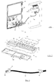
- the electrical distribution enclosure 22, illustrated in FIG. 1, comprises at least one processing unit 20, for example a programmable controller, and electrical components 21 capable of being operated or controlled by this unit.
- the electrical members 21 are for example constituted by elements displays such as indicator lights and control elements such as push buttons.
- the processing unit 20 is housed inside the envelope while the members 21 are carried by a wall 23 of the envelope and are accessible from outside.
- the wall 23 may for example constitute the closure panel of the envelope. It has on its internal face a chassis 24 on which are fixed plates 21a serving to support the members 21.
- the unit 20 and the members 21 are electrically connected via a device interface 1.
- the electrical connection of the interface device 1 to the members 21 and to the unit 20 is produced by connection cables 40 and respectively a cord electric 60 specifically adapted.
- the interface device 1 is intended to be installed on the wall 23 and to proximity to organs 21.
- the interface device 1 illustrated in Figure 2, is a housing 10 having a general parallelepiped shape and oblong. It has a low profile size to be adapted to be housed in the environment of the organs 21.
- the housing 10 consists of a body 11, a printed circuit board not visible in the drawings, and a base 12.
- the body 11 and the base 12 are made of material plastic.
- the base 12 is fixed to the rear of the body 11 in order to protect the card from printed circuit and close the body of the case.
- the rear closure is carried out by attachment and latching means 13 provided on the base 12 which cooperate with additional means 14 for retaining the body 11.
- the housing 10 comprises a fixing part 12a which is constituted by the rear part of its base 12.
- the fixing part 12a is mounted by means adapted either to a plate 21a, or directly to the chassis 24.
- connection terminals 30 are at most equal to the number of eight in order to moderate the size of the housing 10.
- Each terminal 30 is a plug terminal which is provided with two pins of connection, not shown, soldered to the printed circuit.
- the connection of a switchgear 21 to a terminal 30 is produced by at least one connection cable 40 ( Figure 3) which comprises at one of its ends a connector 41 with two elements female connector 42 for plugging into the terminal connection pins.
- the cable 40 comprises at its other end a connector 43 adapted to the type of connection of the apparatus 21.
- this connector is sliding on the cable to adapt the length of the latter between the device 1 and the apparatus 21; when the length is determined, the connector is stopped on the cable by suitable clamping means, the connector being preferably self-stripping.
- the body 11 also comprises, above the printed circuit board, a central and longitudinal recess 50 of length substantially equal to the row of terminals 30.
- the recess 50 has a bottom 51 which has a row of orifices 52 aligned and arranged laterally opposite the connection terminals 30.
- the orifices 52 are in correspondence with electrically conductive elements of the printed circuit board, such as conductive tracks, which are connected to terminal connection pins 30. The conductive parts are thus accessible for an electrical test of the terminals 30 through the orifices 52.
- the bottom 51 also carries a preset electrical identification label for each of the connection terminals 30.
- the recess 50 has a depth which makes it possible to accommodate a cover pivoting 53 so that its front plane Q is located at the level of the facade 11a of the body 11 in the closed position.
- the cover 53 and the longitudinal side walls 50a of the recess 50 have at their ends pivots 54 and notches 55 able to cooperate with each other allowing the articulation of the cover.
- the closure of cover 53 is produced by lugs 56 which can be snapped into openings 50b formed in the side walls 50a of the central recess.
- the cover 53 is preferably transparent to make it visible the preset identification label for the bottom 51 of the recess 50.
- the cover transparent can nevertheless have an electrical identification label on its facade specific to the user which is adapted to slide against shoulders arranged on on the inside of the cover.
- a second row of aligned connection terminals 30 can be provided parallel to the first and symmetrically to the recess 50. Ports additional test 52 are therefore provided in the bottom 51.
- the body 11 of the housing includes an opening 57 integrated in the facade 11a for the passage of a connector 61, for example multi-point, for connection with the processing unit 20 which is mounted on the printed circuit board.
- the link is made by the appropriate electrical cord 60 and provided with a multi-point connector complementary.
- the connector 61 and the electrical cord 60 may be in variant suitable for connection to fieldbus, of the AS-Interface type by example.
- a multi-point connector it is provided between the interface device 1 and the unit 20 a distribution box 70 for connecting the electrical cord 60, information coming from or going to unit 20 at case 70 then being transmitted via two separate cords which are suitable for unit entrances.
- the facade 11a of the housing can be provided an additional opening 58 for the passage of a connection socket of the type low voltage power supply mounted on the printed circuit board.
- This socket can be used to power a given type of organ 21.
- the processing unit 20 is mounted inside the cabinet, while the organs 21 and the interface device 1 are fixed to the chassis 24 of the wall 23.
- the interface device 1 is mounted as close as possible to the members 21 so that the length of the connection cables 40 is minimized.
- connection cables 40 are first wired to the members 21, their associated ends being adapted to the type of terminals of each member.
- the installer can then establish an electrical identification label notifying all of the organ connections and sliding it into the cover transparent 53 of the interface device.
- the cables 40 are then routed to the device 1 where their ends 41 are plugged into terminals 30.
- interface device 1 is connected to the unit 20 via the cord electric 60.
- connection cable 40 which incorporates a supply line and a supply line return conduction, which does not require the use of two cables or wires distinct as in the prior art.
- connection cable 40 which incorporates a supply line and a supply line return conduction, which does not require the use of two cables or wires distinct as in the prior art.
- Such a cable therefore makes it possible to use a simple locating element affixed to the connector 41, and which can carry by example the function of the device 21 instead of the destination of the cable, whereas for wire to wire type wiring, it is necessary to identify each wire, the inscription of its destination being compulsory.
Landscapes
- Engineering & Computer Science (AREA)
- Automation & Control Theory (AREA)
- Microelectronics & Electronic Packaging (AREA)
- Computer Hardware Design (AREA)
- General Engineering & Computer Science (AREA)
- Human Computer Interaction (AREA)
- Connections Arranged To Contact A Plurality Of Conductors (AREA)
Abstract
Description
- la figure 1 est une enveloppe de distribution électrique selon l'invention;
- la figure 2 est une vue en perspective éclatée d'un dispositif d'interface;
- la figure 3 illustre un câble de connexion adapté à se monter sur le dispositif d'interface de la figure 2.
Claims (11)
- Enveloppe pour appareillages électriques comprenant des organes électriques (21) de commande ou visualisation, qui sont portés par une paroi (23) de l'enveloppe en étant accessibles de l'extérieur, une unité (20) de traitement ou commande de ces organes, qui est logée à l'intérieur de l'enveloppe, et un dispositif d'interface électrique (1) entre les organes (21) et l'unité (20), le dispositif d'interface (1) étant constitué d'un boítier (10) comprenant un corps (11) qui loge une carte à circuit imprimé et intègre une rangée de bornes de connexion (30) et un connecteur (61) pour relier la carte à circuit imprimé aux organes (21) et respectivement à l'unité (20), caractérisée en ce que le dispositif d'interface (1) comprend une partie de fixation (12a) montée sur la face interne de la paroi (23) de l'enveloppe à proximité des organes (21), et les bornes (30) du dispositif (1) sont du type à connexion rapide.
- Enveloppe selon la revendication 1, caractérisée en ce que la paroi (23) porte sur sa face interne un châssis (24) sur lequel sont montées des platines (21a) de support pour les organes électriques (21), l'une des platines (21a) servant de support de fixation au dispositif d'interface (1).
- Enveloppe selon la revendication 1, caractérisée en ce que la paroi (23) porte sur sa face interne un châssis (24) sur lequel est fixé le dispositif d'interface (1).
- Enveloppe selon la revendication 1, caractérisée en ce que les bomes (30) du dispositif d'interface sont du type à broches de connexion et le raccordement électrique entre les bornes (30) et les organes (21) est effectué grâce à des câbles de connexion (40) munis chacun à au moins l'une de leurs extrémités d'un connecteur (41) qui est adapté à s'enficher dans les broches de connexion d'une borne (30).
- Enveloppe selon la revendication 4, caractérisée en ce que chaque borne de connexion (30) du dispositif d'interface comprend deux broches de connexion, et le connecteur (41) qui lui est associé comprend deux éléments de connexion femelles (42) correspondants destinés à s'enficher respectivement sur les deux broches de connexion.
- Enveloppe selon la revendication 1, caractérisée en ce que le corps (11) du dispositif d'interface comprend un évidement (50) de longueur sensiblement égale à celle de la rangée de bornes (30), ledit évidement comportant un fond (51) qui est situé au-dessus de la carte à circuit imprimé et qui comprend des orifices (52) disposés latéralement en regard de chacune des bornes de connexion (30), et venant en correspondance avec des éléments électriquement conducteurs de la carte à circuit imprimé pour les rendre accessibles à des tests électriques, les pièces conductrices étant reliées aux bornes de connexion.
- Enveloppe selon la revendication 6, caractérisée en ce que le corps (11) du dispositif d'interface intègre une deuxième rangée longitudinale de bornes de connexion qui est parallèle à la première rangée de bornes et symétrique par rapport à l'évidement (50), le fond (51) de l'évidement central comprenant des orifices de test (52) supplémentaires associés à la deuxième rangée de bornes.
- Enveloppe selon la revendication 6, caractérisée en ce que l'évidement (50) du dispositif d'interface est obturé par un couvercle (53) dont la face avant est adaptée à porter une étiquette de repérage électrique des bornes de connexion propre à l'utilisateur.
- Enveloppe selon la revendication 8, caractérisée en ce que le couvercle (53) est monté pivotant sur des pivots (54) portés par les extrémités latérales de l'évidement (50) et présente des pattes (56) encliquetables dans des ouvertures (50b) ménagées dans les parois de l'évidement.
- Enveloppe selon la revendication 1, caractérisée en ce que le corps (11) du dispositif d'interface comporte une ouverture (58) pour le passage d'une prise d'alimentation à basse tension qui est montée sur la carte à circuit imprimé.
- Enveloppe selon la revendication 4, caractérisée en ce que le câble de connexion (40) est muni à son autre extrémité d'un connecteur (43) auto-dénudant et apte à coulisser sur le câble avant la détermination de longueur de câble nécessaire pour le câblage.
Applications Claiming Priority (2)
| Application Number | Priority Date | Filing Date | Title |
|---|---|---|---|
| FR9705005 | 1997-04-21 | ||
| FR9705005A FR2762473B1 (fr) | 1997-04-21 | 1997-04-21 | Enveloppe pour appareillages electriques |
Publications (1)
| Publication Number | Publication Date |
|---|---|
| EP0889565A1 true EP0889565A1 (fr) | 1999-01-07 |
Family
ID=9506218
Family Applications (1)
| Application Number | Title | Priority Date | Filing Date |
|---|---|---|---|
| EP98400678A Withdrawn EP0889565A1 (fr) | 1997-04-21 | 1998-03-23 | Enveloppe pour appareillages électriques |
Country Status (3)
| Country | Link |
|---|---|
| US (1) | US5903438A (fr) |
| EP (1) | EP0889565A1 (fr) |
| FR (1) | FR2762473B1 (fr) |
Cited By (1)
| Publication number | Priority date | Publication date | Assignee | Title |
|---|---|---|---|---|
| CN106410490A (zh) * | 2016-09-05 | 2017-02-15 | 深圳市安思科电子科技有限公司 | 一种用于网络通讯工程的通讯电缆接线设备 |
Families Citing this family (9)
| Publication number | Priority date | Publication date | Assignee | Title |
|---|---|---|---|---|
| JP2002186136A (ja) * | 2000-12-14 | 2002-06-28 | Yazaki Corp | 電気接続箱 |
| USD483018S1 (en) | 2002-11-21 | 2003-12-02 | Aten International Co. Ltd | Automatic switching device |
| USD482667S1 (en) | 2002-11-26 | 2003-11-25 | Jeff Yu | Receptacle |
| US6717293B1 (en) * | 2003-03-07 | 2004-04-06 | Richard S. Irvine | Electrical safety device |
| US6878891B1 (en) | 2003-11-03 | 2005-04-12 | Siemens Energy & Automation, Inc. | Switchgear enclosure |
| US7858886B2 (en) | 2008-04-07 | 2010-12-28 | Clarolux, L.L.C. | Mounting bracket and method |
| CN202453678U (zh) * | 2012-02-13 | 2012-09-26 | 施耐德电器工业公司 | 一种人机界面装置和包含其的控制柜 |
| US9234914B2 (en) * | 2013-03-15 | 2016-01-12 | Rockwell Automation Technologies Incorporated | Apparatus to verify an electrically safe work condition |
| US20150015234A1 (en) * | 2013-07-11 | 2015-01-15 | Cintas Corporation | Contact voltage detection system and method |
Citations (2)
| Publication number | Priority date | Publication date | Assignee | Title |
|---|---|---|---|---|
| EP0385200A2 (fr) * | 1989-03-01 | 1990-09-05 | Hitachi, Ltd. | Contrôleur programmable avec unité d'affichage amovible |
| EP0654960A1 (fr) * | 1993-11-12 | 1995-05-24 | ELCON INSTRUMENTS S.r.l. | Dispositif d'interconnection de circuit d'utilisation dans des applications industrielles |
Family Cites Families (6)
| Publication number | Priority date | Publication date | Assignee | Title |
|---|---|---|---|---|
| DE3813888A1 (de) * | 1988-04-20 | 1989-11-02 | Schleicher Elektronic Gmbh & C | Modul fuer eine aus mehreren auf einem traeger nebeneinander angeordneten modulen bestehenden steuerung |
| FR2664121B1 (fr) * | 1990-07-02 | 1993-06-18 | Merlin Gerin | Coffret d'appareils electriques basse tension. |
| US5235494A (en) * | 1992-01-16 | 1993-08-10 | The Chamberlain Group, Inc. | Electrical controller having pivotally mounted circuit board support |
| US5398161A (en) * | 1993-07-23 | 1995-03-14 | Excel, Inc. | Telecommunications switch chassis having housing with front and rear compartments divided by interior partition and removable cover over rear compartment |
| US5592475A (en) * | 1993-12-07 | 1997-01-07 | Raychem Corporation | Distributed digital loop system with trunk unit interface |
| FR2730572B1 (fr) * | 1995-02-10 | 1997-03-14 | Schneider Electric Sa | Dispositif d'interface |
-
1997
- 1997-04-21 FR FR9705005A patent/FR2762473B1/fr not_active Expired - Fee Related
-
1998
- 1998-03-23 EP EP98400678A patent/EP0889565A1/fr not_active Withdrawn
- 1998-04-01 US US09/052,983 patent/US5903438A/en not_active Expired - Fee Related
Patent Citations (2)
| Publication number | Priority date | Publication date | Assignee | Title |
|---|---|---|---|---|
| EP0385200A2 (fr) * | 1989-03-01 | 1990-09-05 | Hitachi, Ltd. | Contrôleur programmable avec unité d'affichage amovible |
| EP0654960A1 (fr) * | 1993-11-12 | 1995-05-24 | ELCON INSTRUMENTS S.r.l. | Dispositif d'interconnection de circuit d'utilisation dans des applications industrielles |
Cited By (1)
| Publication number | Priority date | Publication date | Assignee | Title |
|---|---|---|---|---|
| CN106410490A (zh) * | 2016-09-05 | 2017-02-15 | 深圳市安思科电子科技有限公司 | 一种用于网络通讯工程的通讯电缆接线设备 |
Also Published As
| Publication number | Publication date |
|---|---|
| FR2762473B1 (fr) | 1999-05-28 |
| FR2762473A1 (fr) | 1998-10-23 |
| US5903438A (en) | 1999-05-11 |
Similar Documents
| Publication | Publication Date | Title |
|---|---|---|
| EP1037332B1 (fr) | Connecteur basse tension pourvu d'un adaptateur et adaptateur pour un tel connecteur | |
| CA2251995C (fr) | Dispositif d'interface entre equipements d'une installation | |
| NL1022930C1 (nl) | Elektrisch verbindingselement voor automatische assemblage. | |
| FR2552881A1 (fr) | Systeme de controle de sequence extensible | |
| FR2459604A1 (fr) | Centre de commande de moteurs | |
| FR2693516A1 (fr) | Dispositif à soupape. | |
| EP1038731A1 (fr) | Garniture de pavillon de véhicule automobile | |
| FR2762473A1 (fr) | Enveloppe pour appareillages electriques | |
| EP3605749A1 (fr) | Support d'appareillage électrique et appareillage électrique associé | |
| EP3229033B1 (fr) | Bloc d essai doté de prises d entrée et de sortie de type rj45 | |
| CA1186388A (fr) | Module electronique enfichable dans un connecteur de bus | |
| US20110216545A1 (en) | Connecting system for implementing branches on continuous conductors | |
| EP3179582A1 (fr) | Interface de communication pour un tiroir amovible d'un tableau électrique et tableau électrique comportant une telle interface de communication | |
| FR2631747A1 (fr) | Connecteur electrique et ensemble combine incluant un tel connecteur electrique et une plaquette a circuits imprimes | |
| CA1226344A (fr) | Dispositif entree/sortie pour appareil du genre automate programmable, gamme de tels dispositifs et procede pour realiser leur bornier | |
| CA1183229A (fr) | Connecteur electrique a couplage multiple et connecteurs multiples de mesure pour cartes de circuits d'equipement electronique monte en chassis en faisant application | |
| EP0726624B1 (fr) | Dispositif d'interface | |
| EP0550324A1 (fr) | Bornier pour appareil d'automatisation | |
| EP0677757A1 (fr) | Prise adaptable pour précâblage banalisé, pour système de communication | |
| EP0633588A1 (fr) | Accessoire de raccordement | |
| FR2731114A1 (fr) | Perfectionnements aux fiches de prises de diagnostic | |
| EP0904660A1 (fr) | Installation pour la commande et le controle des connexions entre les conducteurs de deux reseaux distincts | |
| FR3077685A1 (fr) | Connecteur, architecture electrique et aeronef | |
| EP0709685A1 (fr) | Appareil de mesure électrique comportant un compartiment de pile à accès protégé | |
| FR2820210A1 (fr) | Unite mobile comprenant un dispositif de comptage et d'enregistrement de l'energie electrique prelevee |
Legal Events
| Date | Code | Title | Description |
|---|---|---|---|
| PUAI | Public reference made under article 153(3) epc to a published international application that has entered the european phase |
Free format text: ORIGINAL CODE: 0009012 |
|
| 17P | Request for examination filed |
Effective date: 19981110 |
|
| AK | Designated contracting states |
Kind code of ref document: A1 Designated state(s): DE ES GB IT |
|
| AX | Request for extension of the european patent |
Free format text: AL;LT;LV;MK;RO;SI |
|
| RAP1 | Party data changed (applicant data changed or rights of an application transferred) |
Owner name: SCHNEIDER ELECTRIC INDUSTRIES SA |
|
| AKX | Designation fees paid |
Free format text: DE ES GB IT |
|
| RAP1 | Party data changed (applicant data changed or rights of an application transferred) |
Owner name: SCHNEIDER ELECTRIC INDUSTRIES SA |
|
| GRAG | Despatch of communication of intention to grant |
Free format text: ORIGINAL CODE: EPIDOS AGRA |
|
| GRAG | Despatch of communication of intention to grant |
Free format text: ORIGINAL CODE: EPIDOS AGRA |
|
| GRAH | Despatch of communication of intention to grant a patent |
Free format text: ORIGINAL CODE: EPIDOS IGRA |
|
| 17Q | First examination report despatched |
Effective date: 20011214 |
|
| STAA | Information on the status of an ep patent application or granted ep patent |
Free format text: STATUS: THE APPLICATION IS DEEMED TO BE WITHDRAWN |
|
| 18D | Application deemed to be withdrawn |
Effective date: 20020426 |