EP0889579A2 - Verfahren und Schaltung zum Steuern des Anlaufens eines einphasigen Asynchronmotors - Google Patents
Verfahren und Schaltung zum Steuern des Anlaufens eines einphasigen Asynchronmotors Download PDFInfo
- Publication number
- EP0889579A2 EP0889579A2 EP98890189A EP98890189A EP0889579A2 EP 0889579 A2 EP0889579 A2 EP 0889579A2 EP 98890189 A EP98890189 A EP 98890189A EP 98890189 A EP98890189 A EP 98890189A EP 0889579 A2 EP0889579 A2 EP 0889579A2
- Authority
- EP
- European Patent Office
- Prior art keywords
- motor
- winding
- phase
- phase winding
- starting
- Prior art date
- Legal status (The legal status is an assumption and is not a legal conclusion. Google has not performed a legal analysis and makes no representation as to the accuracy of the status listed.)
- Withdrawn
Links
- 238000000034 method Methods 0.000 title claims description 14
- 238000004804 winding Methods 0.000 claims abstract description 96
- 239000003990 capacitor Substances 0.000 claims abstract description 10
- 230000005284 excitation Effects 0.000 claims abstract description 7
- 230000003247 decreasing effect Effects 0.000 claims 2
- 230000002542 deteriorative effect Effects 0.000 description 1
Images


Classifications
-
- H—ELECTRICITY
- H02—GENERATION; CONVERSION OR DISTRIBUTION OF ELECTRIC POWER
- H02P—CONTROL OR REGULATION OF ELECTRIC MOTORS, ELECTRIC GENERATORS OR DYNAMO-ELECTRIC CONVERTERS; CONTROLLING TRANSFORMERS, REACTORS OR CHOKE COILS
- H02P1/00—Arrangements for starting electric motors or dynamo-electric converters
- H02P1/16—Arrangements for starting electric motors or dynamo-electric converters for starting dynamo-electric motors or dynamo-electric converters
- H02P1/42—Arrangements for starting electric motors or dynamo-electric converters for starting dynamo-electric motors or dynamo-electric converters for starting an individual single-phase induction motor
- H02P1/44—Arrangements for starting electric motors or dynamo-electric converters for starting dynamo-electric motors or dynamo-electric converters for starting an individual single-phase induction motor by phase-splitting with a capacitor
Definitions
- the invention relates to a method for controlling the start-up a single-phase asynchronous motor with a main phase winding, one auxiliary phase winding and one for auxiliary phase winding operating capacitor connected in series.
- the invention further relates to a startup circuit for one single-phase asynchronous motor with a main phase winding, an auxiliary phase winding and one for auxiliary phase winding in Series switched operating capacitor.
- Electric motors are used in a variety of applications high starting or breakaway torque required.
- the object of the invention is to meet this requirement fulfill. This object is achieved with a generic Method solved in that the impedance in Excitation circuit of the auxiliary phase increased when starting the motor becomes.
- a circuit (start-up circuit) of the type mentioned above, with which the method according to the invention can be carried out, is characterized according to the invention in that the motor impedance in the auxiliary phase when starting the motor higher than is in operation.
- a switch is provided in parallel with the resistor, with which the resistance can be bridged.
- the auxiliary phase winding consists of at least two partial windings exists in series when switching on (starting the motor) are switched, whereas in operation they are connected in parallel are.
- the total impedance of the Auxiliary phase not increased by an additional series resistor, but the individual partial windings of the auxiliary phase winding when the motor is switched on, i.e. in the start-up phase, in series and after starting parallel to each other switched.
- auxiliary phase winding from at least two parallel partial windings exists, of which at least one when switched on Partial winding is switched off.
- the impedance in the main phase when starting the motor is higher than is in operation.
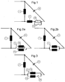
- Fig. 1 is a schematic of a circuit on a single-phase AC network operable asynchronous motor shown, in which a main phase winding 1, an auxiliary phase winding 2 and an operating capacitor 3 to network connections L and N are connected.
- the auxiliary phase winding 2 and the Operating capacitor 3 are in series and parallel to each other switched to the main phase winding 1.
- a series resistor 10 connected to the auxiliary phase winding 2 the can be bridged with the help of a switch 11.
- the motor is switched on, i.e. in its start-up phase Switch 11 opened and closed again after startup, so that the series resistor 10 is bridged. In this way can easily change the torque of the motor in the start-up phase Way be increased.
- auxiliary phase winding 2 consists of two partial windings 12 and 13. It can too more than two partial windings 12 and 13 may be provided, which form the auxiliary phase winding 2.
- the partial windings are 12 and 13 connected in series in the start-up phase, so that the summed Impedances of the partial windings 12 and 13 practically the same Do the job like a series resistor.
- the partial windings 12 and 13 are the Auxiliary phase winding 2 connected in parallel, as shown in Fig. 2b is shown.
- the calculated torque increase in the start-up phase corresponds in this circuit to that in a To achieve doubling of the capacitance of the capacitor 3 would.
- there are more than two partial windings 12 and 13 are provided, then these can be started during the start-up Motors are connected in parallel one after the other that a very good control of current and voltage or torque possible during the start-up phase of the motor.
- the auxiliary phase winding 2 consists of two Partial windings 12 and 13.
- the partial winding 12 - switched off with the help of a switch 14, such as this is shown in Fig. 3.
- a switch 14 After the engine starts the switch 14 closed, so that the winding 12 during operation the motor is switched on.
- all partial windings can be except the first partial winding via switches that correspond to the Switches 14 are arranged, switched off in the start-up phase and one after the other while the motor is starting up be switched on.
- the starting current can be implemented through measures in the Main phase 1 easily limited and a voltage dip can be prevented in the network without taking measures in the auxiliary phase 2, the engine torque during the Startup phase is deteriorating.
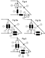
- 5a and 5b is an embodiment of an inventive Circuit shown in which the main phase winding 1 formed by at least two partial windings 1 'and 1 " is.
- FIG. 6 shows an embodiment in which the Main phase winding 1 by two partial windings 1 'and 1 " is formed. Here too more than two partial windings can be made be provided.
- the partial winding 1 ' switched off with the help of a switch 5, as in FIG. 6 see is.
- FIG. 7 shows an example of a circuit according to the invention, in which a winding Hi2 is assigned to the auxiliary winding Hi1 is.
- the main winding Hal is also an additional one Assigned winding Ha2.
- FIG. 8 shows an embodiment of the invention Circuit in which only the auxiliary phase winding Hi1 a additional winding Hi2 is assigned in the start-up phase can be connected in series to the auxiliary phase winding Hi1 can.
- the start-up behavior of a single-phase AC network operable asynchronous motor with a main phase winding 1, an auxiliary phase winding 2, and an operating capacitor 3 to improve is in series for auxiliary phase winding 2, a series resistor 10 is switched, using a Switch 11 can be bridged.
- a switch 11 When the engine starts the switch 11 is open, so that the starting torque the increased impedance in the excitation circuit of auxiliary phase 2 increases becomes. After the motor starts, the switch 11 closed, so that the series resistor 10 of the auxiliary phase winding 2 is bridged when operating the engine.
- a series resistor 4 in series with the main phase winding 1 a series resistor 4 can be switched by means of a switch 5 can be bridged.
- the Switch 5 opened and in operation of the engine, that is after Start up, closed, so that the series resistor 4 bridges is.
Landscapes
- Engineering & Computer Science (AREA)
- Power Engineering (AREA)
- Motor And Converter Starters (AREA)
Abstract
Description
Claims (19)
- Verfahren zum Steuern des Anlaufens eines einphasigen Asynchronmotors mit einer Hauptphasenwicklung (1), einer Hilfsphasenwicklung (2) und einem zur Hilfsphasenwicklung in Serie geschalteten Betriebskondensator (3), dadurch gekennzeichnet, daß die Impedanz im Erregerkreis der Hilfsphase (2) beim Anlaufen des Motors erhöht wird.
- Verfahren nach Anspruch 1, dadurch gekennzeichnet, daß die Impedanz im Erregerkreis der Hilfsphase (2) nach der Anlaufphase wieder verkleinert.
- Verfahren nach Anspruch 1 oder 2, dadurch gekennzeichnet, daß die Impedanz der Hilfsphase (2) von einem höchsten Wert am Beginn des Anlaufens während des Anlaufens nach und nach auf niedrigere Werte verkleinert wird.
- Verfahren nach Anspruch 3, dadurch gekennzeichnet, daß die Impedanz der Hilfsphase (2) stufenweise verkleinert wird.
- Verfahren nach einem der Ansprüche 1 bis 4, dadurch gekennzeichnet, daß die Impedanz im Erregerkreis der Hauptphase (1) beim Anlaufen des Motors erhöht wird.
- Verfahren nach Anspruch 5, dadurch gekennzeichnet, daß die Impedanz der Hauptphase (1) von einem höchsten Wert am Beginn des Anlaufens während des Anlaufens nach und nach auf niedrigere Werte verkleinert wird.
- Verfahren nach Anspruch 6, dadurch gekennzeichnet, daß die Impedanz der Hauptphase (1) stufenweise verkleinert wird.
- Anlaufschaltung für einen einphasigen Asynchronmotor mit einer Hauptphasenwicklung (1), einer Hilfsphasenwicklung (2) und einem zur Hilfsphasenwicklung (2) in Serie geschalteten Betriebskondensator (3), insbesondere zum Ausführen des Verfahrens nach einem der Ansprüche 1 bis 7, dadurch gekennzeichnet, daß die Motorimpedanz in der Hilfsphase(2) beim Anlaufen des Motors höher als im Betrieb ist.
- Schaltung nach Anspruch 8, dadurch gekennzeichnet, daß zur Hilfsphasenwicklung (2) ein zuschaltbarer Widerstand (10) in Serie geschaltet ist (Fig. 1, 4).
- Schaltung nach Anspruch 9, dadurch gekennzeichnet, daß parallel zum Widerstand (10) ein Schalter (11) vorgesehen ist, mit dem der Widerstand (10) überbrückbar ist (Fig. 1, 4).
- Schaltung nach Anspruch 8, dadurch gekennzeichnet, daß die Hilfsphasenwicklung (2) aus wenigstens zwei Teilwicklungen (12, 13, Hil, Hi2) besteht, die während des Anlaufens des Motors in Serie und während des Betriebes des Motors parallel geschaltet sind (Fig. 2a, 2b, 5a, 5b, 7, 8).
- Schaltung nach Anspruch 8, dadurch gekennzeichnet, daß die Hilfsphasenwicklung (2) aus wenigstens zwei parallel geschalteten Teilwicklungen (12, 13) besteht, von denen während des Anlaufens des Motors wenigstens eine Teilwicklung (12) weggeschaltet ist (Fig. 3, 6).
- Schaltung nach Anspruch 12, dadurch gekennzeichnet, daß in Serie zur wegschaltbaren Teilwicklung (12) ein Schalter (14) vorgesehen ist (Fig. 3, 6).
- Schaltung nach einem der Ansprüche 8 bis 13, dadurch gekennzeichnet, daß die Impedanz in der Hauptphase (1) beim Anlaufen des Motors höher als im Betrieb ist.
- Schaltung nach Anspruch 14, dadurch gekennzeichnet, daß in Serie zur Hauptphasenwicklung (1) ein zuschaltbarer Widerstand (4) geschaltet ist (Fig. 4).
- Schaltung nach Anspruch 15, dadurch gekennzeichnet, daß parallel zum Widerstand (4) ein Schalter (5) vorgesehen ist (Fig. 4).
- Schaltung nach Anspruch 14, dadurch gekennzeichnet, daß die Hauptphasenwicklung (1) aus wenigstens zwei Teilwicklungen (1', 1") besteht, die beim Einschalten in Serie und bei Betrieb des Motors parallel geschaltet sind (Fig. 5a, 5b).
- Schaltung nach Anspruch 14, dadurch gekennzeichnet, daß die Hauptphasenwicklung (1) aus wenigstens zwei parallel geschalteten Teilwicklungen (1', 1"; Hal, Ha2) besteht, von denen beim Hochlauf des Motors wenigstens eine Teilwicklung (1"; Ha2) weggeschaltet ist (Fig. 6, 7).
- Schaltung nach Anspruch 18, dadurch gekennzeichnet, daß in Serie zur wegschaltbaren Teilwicklung (1"; Ha2) ein Schalter (5, S) vorgesehen ist (Fig. 6).
Applications Claiming Priority (2)
| Application Number | Priority Date | Filing Date | Title |
|---|---|---|---|
| AT1148/97 | 1997-07-03 | ||
| AT114897 | 1997-07-03 |
Publications (2)
| Publication Number | Publication Date |
|---|---|
| EP0889579A2 true EP0889579A2 (de) | 1999-01-07 |
| EP0889579A3 EP0889579A3 (de) | 1999-01-20 |
Family
ID=3507651
Family Applications (1)
| Application Number | Title | Priority Date | Filing Date |
|---|---|---|---|
| EP98890189A Withdrawn EP0889579A3 (de) | 1997-07-03 | 1998-06-30 | Verfahren und Schaltung zum Steuern des Anlaufens eines einphasigen Asynchronmotors |
Country Status (1)
| Country | Link |
|---|---|
| EP (1) | EP0889579A3 (de) |
Cited By (3)
| Publication number | Priority date | Publication date | Assignee | Title |
|---|---|---|---|---|
| EP1146632A1 (de) * | 2000-04-14 | 2001-10-17 | Crouzet Automatismes | Elektromechanische Regelvorrichtung für Synchronmotoren |
| CN100452634C (zh) * | 2005-11-11 | 2009-01-14 | 艾默生电气公司 | 单相电机软起动器和具有该软起动器的单相电机 |
| CN104931972A (zh) * | 2014-03-21 | 2015-09-23 | 福特全球技术公司 | 使用超声波相位阵列的对象检测 |
Family Cites Families (9)
| Publication number | Priority date | Publication date | Assignee | Title |
|---|---|---|---|---|
| US3484670A (en) * | 1967-10-11 | 1969-12-16 | Marathon Electric Mfg | Soft start capacitor-start motor |
| DE1936880A1 (de) * | 1969-04-22 | 1970-12-23 | Elmasch Bau Veb K | Schaltungsanordnung zur kontaktlosen Steuerung des Hilfsphasenstromes von Einphasenmotoren |
| US3955170A (en) * | 1974-11-29 | 1976-05-04 | Texas Instruments Incorporated | Solid state switch |
| JPS54121916A (en) * | 1978-03-16 | 1979-09-21 | Toshiba Corp | Single phase ac motor control system |
| FR2476931A2 (fr) * | 1980-02-22 | 1981-08-28 | Normandie Moteurs Electr | Moteur eclecrique equipant un bruleur a combustible, et bruleur a mazout comportant un tel moteur. |
| JPS5752389A (en) * | 1980-09-16 | 1982-03-27 | Hitachi Ltd | Starting circuit for split-phase capacitor run motor |
| JPS58224579A (ja) * | 1982-06-23 | 1983-12-26 | Nippon Denso Co Ltd | 電動圧縮機 |
| JPS63305776A (ja) * | 1987-06-08 | 1988-12-13 | Hitachi Ltd | 単相モ−トル |
| JP2635348B2 (ja) * | 1988-02-03 | 1997-07-30 | 松下冷機株式会社 | 分相始動単相誘導電動機の始動装置 |
-
1998
- 1998-06-30 EP EP98890189A patent/EP0889579A3/de not_active Withdrawn
Cited By (4)
| Publication number | Priority date | Publication date | Assignee | Title |
|---|---|---|---|---|
| EP1146632A1 (de) * | 2000-04-14 | 2001-10-17 | Crouzet Automatismes | Elektromechanische Regelvorrichtung für Synchronmotoren |
| FR2807891A1 (fr) * | 2000-04-14 | 2001-10-19 | Crouzet Automatismes | Dispositif de commande electromecanique a moteur synchrone |
| CN100452634C (zh) * | 2005-11-11 | 2009-01-14 | 艾默生电气公司 | 单相电机软起动器和具有该软起动器的单相电机 |
| CN104931972A (zh) * | 2014-03-21 | 2015-09-23 | 福特全球技术公司 | 使用超声波相位阵列的对象检测 |
Also Published As
| Publication number | Publication date |
|---|---|
| EP0889579A3 (de) | 1999-01-20 |
Similar Documents
| Publication | Publication Date | Title |
|---|---|---|
| EP1860757A1 (de) | Elektrische Maschine mit Teilwicklungsschaltung | |
| EP0771065B1 (de) | Verfahren zum Anlaufen drehzahlveränderlicher elektrischer Antriebe | |
| DE2222517B2 (de) | Schaltvorrichtung in hybrid-technik zum lastfreien schalten von mit alternierender spannung gespeisten stromverbrauchern mit beliebigem phasenverschiebungswinkel | |
| DE69215632T2 (de) | Starten von Mehrfachgeschwindigkeitsmotoren von einer niedrigen Geschwindigkeitsverbindung aus | |
| DE3107654C2 (de) | Teilwicklungsschaltung zum Anfahren eines Drehstrommotors | |
| DE69803885T2 (de) | Steuerungsvorrichtung für elektrische motoren | |
| EP0045951B1 (de) | Verfahren zum Betrieb eines Umrichters mit Gleichstromzwischenkreis zur Speisung einer Drehfeldmaschine | |
| EP1071200A2 (de) | Elektronisch kommutierbarer Motor | |
| DE2838716C3 (de) | Elektrische Schaltungsanordnung zum Betrieb eines mit Wechselspannung gespeisten Elektromotors | |
| EP0635927B1 (de) | Permanentmagnet-Gleichstrommotor | |
| CH663698A5 (de) | Schaltungsanordnung zur speisung eines dreiphasigen induktionsmotors aus einem einphasennetz. | |
| EP0872947A1 (de) | Verfahren und Schaltung zum Begrenzen des Einschaltstromes | |
| DE3342206C2 (de) | ||
| DE2530259C3 (de) | Drehzahlstellbare Anordnung mit einem Einphasen-Komutatormotor | |
| DE735366C (de) | Einrichtung zur selbsttaetigen spannungsabhaengigen Steuerung von Anlass- und Bremsvorgaengen bei Elektromotoren | |
| EP0043138B1 (de) | Elektronische Kommutierungseinrichtung für Gleichstrommaschinen mit mehreren Wicklungssträngen | |
| DE262321C (de) | ||
| DE200661C (de) | ||
| EP0366996B1 (de) | Drehfeldmotor an Einphasennetz | |
| DE10237434A1 (de) | Spannungsversorgung für Elektromotoren und Elektromotor, sowie Stellantrieb für diese Spannungsversorgung | |
| AT406213B (de) | Schaltung zum steuern des hochlaufes eines einphasigen asynchronmotors | |
| WO2017013117A1 (de) | Verfahren zum betreiben eines frequenzumrichters und frequenzumrichter | |
| DE3236605C1 (de) | Schweißgerät mit einem Drehstromtransformator | |
| DE669085C (de) | Einphasen-Induktionsmotor | |
| DE4305605A1 (de) | Anordnung zum Betrieb eines elektromotorischen Antriebes eines Kompressors eines Kühlaggregates für elektrische Schaltschränke |
Legal Events
| Date | Code | Title | Description |
|---|---|---|---|
| PUAI | Public reference made under article 153(3) epc to a published international application that has entered the european phase |
Free format text: ORIGINAL CODE: 0009012 |
|
| PUAL | Search report despatched |
Free format text: ORIGINAL CODE: 0009013 |
|
| AK | Designated contracting states |
Kind code of ref document: A2 Designated state(s): AT BE CH CY DE DK ES FI FR GB GR IE IT LI LU |
|
| AX | Request for extension of the european patent |
Free format text: AL;LT;LV;MK;RO;SI |
|
| AK | Designated contracting states |
Kind code of ref document: A3 Designated state(s): AT BE CH CY DE DK ES FI FR GB GR IE IT LI LU MC NL PT SE |
|
| AX | Request for extension of the european patent |
Free format text: AL;LT;LV;MK;RO;SI |
|
| 17P | Request for examination filed |
Effective date: 19990604 |
|
| AKX | Designation fees paid |
Free format text: AT BE CH CY DE DK ES FI FR GB GR LI |
|
| RBV | Designated contracting states (corrected) |
Designated state(s): AT BE CH CY DE DK ES FI FR GB GR IE IT LI LU |
|
| RBV | Designated contracting states (corrected) |
Designated state(s): AT BE CH DE ES FR GB GR IT LI NL SE |
|
| RBV | Designated contracting states (corrected) |
Designated state(s): AT BE CH DE ES FR GB IT LI LU NL SE |
|
| 17Q | First examination report despatched |
Effective date: 20000222 |
|
| GRAJ | Information related to disapproval of communication of intention to grant by the applicant or resumption of examination proceedings by the epo deleted |
Free format text: ORIGINAL CODE: EPIDOSDIGR1 |
|
| GRAP | Despatch of communication of intention to grant a patent |
Free format text: ORIGINAL CODE: EPIDOSNIGR1 |
|
| GRAP | Despatch of communication of intention to grant a patent |
Free format text: ORIGINAL CODE: EPIDOSNIGR1 |
|
| STAA | Information on the status of an ep patent application or granted ep patent |
Free format text: STATUS: THE APPLICATION IS DEEMED TO BE WITHDRAWN |
|
| 18D | Application deemed to be withdrawn |
Effective date: 20080103 |