EP0889652A2 - Méthode et dispositif de codage du contour d'un objet fondé sur une technique d'estimation de mouvement de contours - Google Patents
Méthode et dispositif de codage du contour d'un objet fondé sur une technique d'estimation de mouvement de contours Download PDFInfo
- Publication number
- EP0889652A2 EP0889652A2 EP97306899A EP97306899A EP0889652A2 EP 0889652 A2 EP0889652 A2 EP 0889652A2 EP 97306899 A EP97306899 A EP 97306899A EP 97306899 A EP97306899 A EP 97306899A EP 0889652 A2 EP0889652 A2 EP 0889652A2
- Authority
- EP
- European Patent Office
- Prior art keywords
- contour
- contours
- current
- previous
- global
- Prior art date
- Legal status (The legal status is an assumption and is not a legal conclusion. Google has not performed a legal analysis and makes no representation as to the accuracy of the status listed.)
- Granted
Links
Images


Classifications
-
- G—PHYSICS
- G06—COMPUTING OR CALCULATING; COUNTING
- G06T—IMAGE DATA PROCESSING OR GENERATION, IN GENERAL
- G06T9/00—Image coding
- G06T9/20—Contour coding, e.g. using detection of edges
-
- H—ELECTRICITY
- H04—ELECTRIC COMMUNICATION TECHNIQUE
- H04N—PICTORIAL COMMUNICATION, e.g. TELEVISION
- H04N19/00—Methods or arrangements for coding, decoding, compressing or decompressing digital video signals
- H04N19/50—Methods or arrangements for coding, decoding, compressing or decompressing digital video signals using predictive coding
- H04N19/503—Methods or arrangements for coding, decoding, compressing or decompressing digital video signals using predictive coding involving temporal prediction
- H04N19/51—Motion estimation or motion compensation
- H04N19/527—Global motion vector estimation
-
- H—ELECTRICITY
- H04—ELECTRIC COMMUNICATION TECHNIQUE
- H04N—PICTORIAL COMMUNICATION, e.g. TELEVISION
- H04N19/00—Methods or arrangements for coding, decoding, compressing or decompressing digital video signals
- H04N19/50—Methods or arrangements for coding, decoding, compressing or decompressing digital video signals using predictive coding
- H04N19/503—Methods or arrangements for coding, decoding, compressing or decompressing digital video signals using predictive coding involving temporal prediction
- H04N19/51—Motion estimation or motion compensation
- H04N19/537—Motion estimation other than block-based
- H04N19/54—Motion estimation other than block-based using feature points or meshes
-
- H—ELECTRICITY
- H04—ELECTRIC COMMUNICATION TECHNIQUE
- H04N—PICTORIAL COMMUNICATION, e.g. TELEVISION
- H04N19/00—Methods or arrangements for coding, decoding, compressing or decompressing digital video signals
- H04N19/50—Methods or arrangements for coding, decoding, compressing or decompressing digital video signals using predictive coding
- H04N19/503—Methods or arrangements for coding, decoding, compressing or decompressing digital video signals using predictive coding involving temporal prediction
- H04N19/51—Motion estimation or motion compensation
- H04N19/537—Motion estimation other than block-based
- H04N19/543—Motion estimation other than block-based using regions
Definitions
- the present invention relates to a method and apparatus for encoding a contour of an object expressed in a video signal; and, more particularly, to a method and apparatus capable of generating control signals for systematically managing matching degrees between contours in a current frame and corresponding contours in a previous frame.
- One of such techniques for encoding video signals for a low bit-rate encoding system is the so-called object-oriented analysis-synthesis coding technique( see Michael Hötter, "Object-Oriented Analysis-Synthesis Coding Based on Moving Two-Dimensional Objects", Signal Processing: Image Communication 2 , 409-428(December, 1990)).
- an input video image is divided into objects; and three sets of parameters for defining the motion, contour and pixel data of each object are processed through different encoding channels.
- contour information is important for the analysis and synthesis of the object shape.
- a classical coding method for representing the contour information is a chain coding method.
- the chain coding method requires a substantial amount of bits for the representation thereof, although there is no loss in the contour information.
- DST discrete sine transform
- a shape difference between the current contour and its matched previous contour, index data assigned to the matched previous contour, and a spatial displacement, i.e., a motion vector, between the current contour and the matched previous contour are multiplexed and then the multiplexed data is transmitted as encoded contour data.
- the above method sporadically provides contour encoding information including the shape difference, the index data, and the motion vector, which corresponds to each of the current contours in the current frame, there still is generated a substantial amount of data to be transmitted and it may be difficult to exactly estimate the amount of the data. Consequently, it is preferable to provide control signals for systematically managing the matching degrees between the current contours and their matched previous contours to thereby effectively incorporate the contour encoding information and further reduce the volume of transmission data in order to successfully implement a low-bit rate codec system having, e.g., a 64 kb/s transmission channel bandwidth.
- a method for encoding a contour of an object in a current frame based on a previous frame comprising the steps of: (a) generating a global motion vector representing a displacement between the current and the previous frames which yields a largest number of overlapping object pixels therebetween; (b) detecting the contours of the objects in the previous frame as previous contours, providing a contour number representing the number of the previous contours, and assigning index data to each of the previous contours in response to a predetermined processing order; (c) choosing one of the contours in the current frame as a current contour; (d) determining an optimum contour among the previous contours and setting a displacement between the current contour and the optimum contour as a local motion vector, the optimum contour being the one most similar to the current contour; (e) producing a predicted contour by shifting the optimum contour based on the global and the local motion vector
- an apparatus for encoding a contour of an object in a current frame based on a previous frame, wherein the respective current and the previous frames include one or more objects, each of the objects having a contour which comprises: a global motion vector detecting block for generating a global motion vector representing a displacement between the current and the previous frames which yields a largest number of overlapping object pixels therebetween; a previous contour providing block for detecting contours of the objects in the previous frame as previous contours, providing a contour number representing the number of the previous contours, and assigning index data to each of the previous contours in response to a predetermined processing order; a current contour providing block for choosing one of the contours in the current frame as a current contour; an optimum contour determining block for detecting, for each of the current contours in the current frame, an optimum contour among the previous contours and setting a displacement between the current contour and the optimum contour as a local motion vector, the optimum contour being the one most similar to the current
- FIG. 1 there is shown a schematic block diagram of an inventive apparatus 5 for encoding contours in a frame signal.
- a contour image signal of a current frame having one or more objects therein is inputted to a contour detection unit 100 and a motion estimation unit 300 via a line L50 in a form of a segmentation mask, wherein each pixel in the segmentation mask has a label identifying a region where it belongs to. For instance, a pixel in a background has a label "0" and each pixel in an object is labeled by one of non-zero values.
- the contour detection unit 100 detects contours from the input segmentation mask and determines a processing order of each of the contours included in the contour image signal according to a predetermined processing order; and sequentially outputs contour information for each of the contours in the current frame, wherein the contour information includes contour data representing positions of contour pixels on a contour.
- the contour information on a line L10 from the contour detection unit 100 is provided as current contour information to a contour encoding unit 200, and a motion estimation unit 300.
- the motion estimation unit 300 detects a previous contour most similar to the current contour on the line L10 as an "optimum contour" based on the current contour image signal on the line L50, the current contour information on the line L10 and a reconstructed previous contour image signal coupled thereto from a frame memory 700 via a line L30.
- the reconstructed previous contour image signal represents a previous frame which is in the form of a segmentation mask, each pixel therein having a label identifying a region where it belongs to.
- Outputs of the motion estimation unit 300 on lines L20 and L40 are the index data of the optimum contour and motion information representing a displacement between the current contour and the optimum contour.
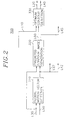
- the motion estimation unit 300 will be described in detail with reference to Figs. 2 and 3.
- the motion estimation unit 300 includes a global motion vector detection block 310, a predicted contour image generation block 320, and an optimum contour detection block 330.
- the global motion vector detection block 310 uses the previous contour image signal on the line L30 and the current contour image signal on the line L50, detects a global motion vector(GMV) representing a displacement between the current and the previous frames which yields a largest number of overlapping object pixels therebetween. Detection of the GMV is carried out within a predetermined search range of, e.g., +/- 16 pixels.
- the GMV derived at the global motion vector detection block 310 is fed to the predicted contour image generation block 320 and provided on lines L22 and L42 leading to the motion compensation unit 400 and a data stream formation unit 800, respectively.
- the predicted contour image generation block 320 detects contours in the predicted contour image; assigns index data to each of the contours included in the predicted contour image according to the predetermined processing order; and sequentially outputs contour information for each of the contours in the predicted contour image, wherein the contour information includes contour data representing positions of contour pixels on a contour in the predicted contour image and index data thereof. Contour information for each of the predicted contours detected at the predicted contour image generation block 320 is fed on a line L60.
- the predicted contour image generation block 320 also detects the number of the contours in the predicted contour image, which is same as that of the previous frame, and provides it as a contour number L onto a line L45.
- an optimum contour based on predicted contour information on the line L60 and current contour information on the line L10, an optimum contour, a predicted contour most similar to the current contour, is detected among predicted contours residing within a preset search range, e.g., +/- 8 pixels of the current contour; and a local motion vector(LMV) representing a spatial displacement between the current contour and the optimum contour and the index data of the optimum contour are outputted on the lines L20 and L40.
- a preset search range e.g., +/- 8 pixels of the current contour
- optimum contour detection block 330 which includes a candidate contour determination sector 331, a matching sector 333, and an optimum contour determination sector 335.
- the candidate contour determination sector 331 detects predicted contours residing within the preset search range from the current contour and calculates lengths of the current and the detected predicted contours based on the current contour information and the predicted contour information on the lines L10 and L60, respectively. Thereafter, the lengths of the current contours and each of those predicted contours within the preset search range are compared. If a difference between the length of a current contour and that of a predicted contour is smaller than M times the shorter one of the two contours, the predicted contour is determined as a candidate contour for the current contour, M being a predetermined number. After determining one or more candidate contours for the current contour, indication signals identifying those candidate contours, e.g., index data of the candidate contours, are fed to the matching sector 333.
- the length of a contour can be defined by, for example, the number of contour pixels which constitute the contour.
- the candidate contours can be determined based on the numbers of pixels positioned inside the respective contours in lieu of the lengths thereof.
- the matching sector 333 retrieves contour information for each candidate contour from the predicted contour image generation block 320 via the line L60 in response to the indication signals inputted thereto. Subsequently, the current contour and its candidate contour are matched based on the current contour information on the line L10 and the candidate contour information on the line L60. After matching the current contour with each candidate contour, the matching sector 333 provides the optimum contour determination sector 335 with matching information for each candidate contour.
- the matching information includes index data, a motion displacement and a matching length for a candidate contour.
- the candidate contour is displaced by, e.g., a one pixel basis within the preset search range, and matching segments of the current and the candidate contours at each displacement are determined.
- the total length of the matching segments is computed for each displacement.
- the computed lengths are then compared with one another and the largest one thereof is determined as the matching length for the candidate contour and the displacement which yields the largest length is set as the motion displacement for the candidate contour.
- FIG. 5 depicts a current contour 10 and a candidate contour 20 overlapping with each other. After overlapping the contours 10 and 20, the intersection points therebetween such as PV1 to PV6, E1 and E2 are detected and lengths of the overlapping segments PV6-PV1, PV2-PV3, E1-E2, and PV4-PV5 are calculated. If the length of an overlapping segment is greater than a threshold value TH1, the overlapping segment is determined as a matching segment. In Fig. 5, it is assumed that the length of the overlapping segment between E1 and E2 is not greater than the TH1; and the lengths of the remaining overlapping segments are greater than the TH1.
- the remaining overlapping segments e.g., PV2 to PV3, PV4 to PV5, and PV6 to PV1 are determined as the matching segments.
- determination of the matching segment can be carried out based on the number of contour pixels residing on a given overlapping segment in lieu of the length thereof.
- the matching lengths of the candidate contours are compared with each other; and a candidate contour corresponding to a matching length of a maximum value is declared as the optimum contour of the current contour.
- the motion displacement corresponding to the optimum contour is set as the local motion vector(LMV).
- Outputs from the optimum contour determination sector 335 on the lines L20 and L40 are the LMV and the index data of the optimum contour.
- the index data of the optimum contour is also fed to the candidate contour determination sector 331 via a line L25 so as to prevent the sector 331 from selecting the predicted contour already determined as the optimum contour as a candidate contour in the following matching processes anymore. Therefore, each of the predicted contours in the predicted contour image has only one chance to be chosen as an optimum contour.
- the motion compensation unit 400 generates a predicted current contour by retrieving the contour information corresponding to the optimum contour from the frame memory 700 via the line L30 based on the GMV on the line L22, and the LMV and the index data of the optimum contour on the line L20, wherein the predicted current contour represents the optimum contour shifted by the sum of the GMV and the LMV.
- the output to the contour encoding unit 200 and a reconstruction unit 600 provided via a line L55 from the motion compensation unit 400 is the predicted current contour information representing position data of contour pixels constituting the predicted current contour.
- the contour encoding unit 200 detects an error representing a difference between the current contour and the predicted current contour based on the predicted current contour information on the line L55 and the current contour information on the line L10; and encodes the error to thereby provide a coded error.
- the coded error is transferred to a contour decoding unit 500 and the data stream formation unit 800.
- the contour decoding unit 500 decodes the coded error to thereby provide a decoded error to the reconstruction unit 600.
- the decoded error from the contour decoding unit 500 is utilized in reconstructing the current image signal together with the predicted current contour information fed thereto via the line L55.
- the reconstruction unit 600 assigns a label to each pixel included in each of contours constituting the frame. Therefore, each pixel in the segmentation mask has a label identifying a region where it belongs to. Then, the reconstructed current contour image signal is stored at the frame memory 700 and is utilized as a reconstructed previous image signal for the next current contour image signal.
- the data stream formation unit 800 provides encoded contour data containing control signals, e.g., flag signals, to a transmitter(not shown) for the transmission thereof based on the coded error on a line L70, the GMV on the line L42, the LMV and the index data of the optimum contour on the line L40, and the contour number L on the line L45, wherein the flag signals represent matching degrees between the contours in the current frame and those in the previous frame to thereby effectively transmit the encoded results produced based on the contour motion estimation technique.
- control signals e.g., flag signals
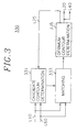
- FIG. 4 there is shown a detailed block diagram of the data stream formation unit 800 containing a storage block 820, a flag signal generation block 840, and a multiplexor (MUX) 860.
- a storage block 820 containing a storage block 820, a flag signal generation block 840, and a multiplexor (MUX) 860.
- MUX multiplexor
- the storage block 820 For each of the contours in the current frame, the storage block 820 stores contour encoding information including the LMV and the index data on the line L40 and the coded error on the line L70, corresponding to each of the current contours; provides the index data to the flag signal generation block 840 via a line L76; and produces a first and a second state signals onto lines L72 and L74, respectively, based on the coded error and the LMV stored therein.
- the first and the second state signals represent states of the coded error and the LMV. That is, the first state signal depicts whether the encoded error has a zero value or not; and the second state signal represents whether there is the LMV or not and, if there is, further represents whether the LMV is a zero value or not. Furthermore, the storage block 820 provides the MUX 860 with the coded error and the LMV via lines L82 and L84, respectively, in response to an output control signal fed from the flag signal generation block 840 through a line L78.
- the flag signal generation block 840 produces the output control signal and flag signals based on the index data on the line L76, the first and the second state signals on the lines L72 and L74, and the contour number L on the line L45.
- the flag signals are utilized to systematically represent matching degrees between the current contours and their corresponding previous contours.
- matching degrees between the current contours and the previous contours are determined, based on the index data and the first and the second state signals, as follows: MATCHING DEGREE ERROR LMV INDEX DATA GM ZERO ZERO Y LM ZERO Y Y PM Y ZERO Y Y Y NM Y N N wherein the letter 'Y' represents that its corresponding value has a non-zero value; the letter 'N' shows that its corresponding value has no value; and 'ZERO' depicts that its corresponding value has a zero value.
- the matching degree GM represents that a current contour is perfectly matched with one of the previous contours by shifting the previous frame based on the GMV, i.e., by global motion compensation, and, therefore, in the matching degree GM, there exists the index data while the coded error, i.e., ERROR, and the LMV have zero values.
- the matching degree LM illustrates that a current contour is perfectly matched with one of the previous contours by the global and local motion compensation and, in this case, there are the LMV having a non-zero value and the index data while the coded error has a zero value, wherein the local motion compensation is carried out by shifting the previous contours in the preset search range after the global motion compensation.
- the matching degree PM indicates that a current contour is partially matched with one of the previous contours by the global and local motion compensation and, in this condition, there are two kinds of data conditions as shown in the [TABLE 1].
- the LMV is a zero value. Therefore, it means that a previous contour matched with a current contour by the global motion compensation is the optimum contour of the current contour.
- the index data and the LMV there are the coded error, the index data and the LMV, corresponding to the current contour, having a non-zero value.
- the matching degree NM describes that a current contour is matched with none of the previous contours and, therefore, the coded error is only fed to the storage block 820, wherein the coded error is an encoding result obtained by intra-encoding the current contour.
- the flag signals are produced based on the matching degrees between the current contours and the previous contours.
- the flag signals includes four signals such as Gfs_flag, Global_flag, Contour_flag, and Contour_flag_status.
- Gfs_flag Global_flag
- Contour_flag Contour_flag_status
- the Gfs_flag signal representing whether the number of previous contours being perfectly matched with current contours by the global motion compensation belongs to a selected range or not, has a logic value as follows: 1 if L ⁇ 4xGPM 0 if L ⁇ 4xGPM wherein GPM is the number of previous contours which are perfectly matched with current contours by the global motion compensation; and L is the contour number.
- the Gfs_flag signal it can be recognized whether the Global_flag signal is produced or not. That is, if the Gfs_flag signal has a logic value 1, the Global_flag signal is outputted, and, if otherwise, the Global-flag signal is not generated.
- the Global_flag signal being produced when the Gfs_flag signal has a logic value 1, consists of L bits, each bit representing whether or not its corresponding previous contour is perfectly matched with one of the current contours by the global motion compensation. That is, if the Global_flag signal contains a bit having a logic value 1, it indicates the corresponding previous contour is completely matched with one of the current contours.
- the Contour_flag signal is represented by M bits if the Gfs_flag signal has a logic value 1, each bit showing whether or not its corresponding previous contour is perfectly or partially matched with one of the current contours based on the global and local motion compensation, M being L-GPM.
- the Contour_flag signal defines the rest of previous contours except the previous contours perfectly matched with one of the current contours by the global motion compensation. That is, if the Contour_flag signal has a bit of a logic value 1, its corresponding previous contour is matched with one of the current contours. If otherwise, its corresponding previous contour is not matched with any current contour.
- the Contour_flag signal contains L bits to define whether each of the previous contours is matched with one of the current contours by the global and local motion compensation.
- the Contour_flag_status signal represents whether a previous contour is completely matched with one of the current contours based on the global and local motion compensation, wherein the Contour_flag_status signal includes CPM bits, CPM being the number of previous contours which are perfectly or partially matched with one of the current contours based on the global and local motion compensation. However, the CPM does not contain the previous contours corresponding to the GPM. Also, if a previous contour is matched with none of the current contours, its corresponding bit is not within the Contour_flag_status signal.
- the Contour_flag_status signal is represented by using CPM+GPM bits and describes matching degrees of previous contours which are completely or partially matched with current contours by the global and local motion compensation.
- the flag signals produced at the flag signal generation block 840 as explained above are fed to the MUX 860 via a line L80. Meantime, the flag signal generation block 840 provides the output control signal to the storage block 820.
- the storage block 820 In response to the output control signal, the storage block 820 provides sequences of the coded errors and the LMVs for the current frame to the MUX 860 through lines L82 and L84, respectively.
- the sequences of the coded errors and the LMVs follow the processing order of the previous contours in the previous frame. And, coded errors for current contours which are not matched with any of the previous contours are sequentially outputted after those for matched current contours.
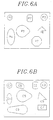
- Figs. 6A and 6B there are exemplarily demonstrated a previous and a current frames containing a plurality of contours, respectively.
- the previous frame in Fig. 6A includes 7 number of previous contours having index data P1 to P7 and the current frame in Fig. 6B consists of 9 number of current contours represented by index data C1 to C9 on requirement.
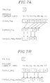
- FIG. 7A and 7B there are shown two examples of the flag signals produced based on the previous and the current frames in Figs. 6A and 6B.
- the current contours C1 and C3 are completely matched with the previous contours P1 and P3, respectively, by the global motion compensation; the current contour C2 is perfectly matched with the previous contour P2 by the local motion compensation executed after the global motion compensation; the current contours C4, C5, and C6 are partially matched with the previous contours P4, P5, and P6, respectively, by the global and local motion compensation; the current contours C7, C8, and C9 are matched with none of the previous contours; and the previous contour P7 is not matched with any current contour.
- the contour number L is 7 and the GPM is 2, L becomes smaller than 4xGPM.
- the Gfs_flag signal has a logic value 1 and the Global_flag, Contour_flag, and Contour_flag_status signals are determined as shown in Fig. 7A based on the definitions of the flag signals.
- the bit arrangements of the flag signals depend on the processing order of the previous contours. Consequently, considering the flag signals, the matching degrees between the previous contours and the current contours can be noticed and the sequences of the LMVs and the coded errors corresponding to the matched contours are also determined. That is, in the first example, there exist the LMVs corresponding to the previous contours P1 to P6 in view of the [TABLE 1].
- the sequence of the LMVs for the matched contours follows a sequence of P1-P2-P3-P4-P5-P6 although the LMVs corresponding to the previous contours P1 and P3 have zero values.
- the sequence of the coded errors for the matched contours is related to the processing order of the current and the previous contours.
- the sequence of the coded errors is determined according to a sequence of P1-P2-P3-P4-P5-P6-C7-C8-C9, wherein the coded errors for the current contours C1 to C3 corresponding to the previous contours P1 to P3 have zero values and the coded errors for the current contours C7 to C9 have been obtained by intra-encoding the contours C7 to C9.
- the Gfs_flag signal has a logic value 0 and the Contour_flag and Contour_flag_status signals are determined as shown in Fig. 7B except the Global_flag signal. According to the flag signals in Fig.
- the LMVs corresponding to the previous contours P1 to P6 exist in view of the [TABLE 1] and the LMVs for the matched contours are transferred in the same sequence of P1-P2-P3-P4-P5-P6.
- the LMV corresponding to the previous contour P1 only has a zero value because the previous contour P3 is partially matched with the current contour C3.
- the sequence of the coded errors for the current contours is determined in response to a sequence of P1-P2-P3-P4-P5-P6-C7-C8-C9, wherein the coded errors for the current contours C1 and C2 corresponding to the previous contours P1 and P2 have zero values and the coded errors for the current contours C7 to C9 were obtained by intra-encoding the contours C7 to C9.
- the flag signals and the sequences of the coded errors and LMVs for the current frame are produced at the flag signal generation block 840 and the storage block 820, and then provided to the MUX 860.
- the encoded contour data is produced to a transmitter(not shown) for the transmission thereof based on the GMV on the line L42, the flag signals on the line L80, the sequence of the coded errors on the line L82, and the sequence of the LMVs on the line L84.
Landscapes
- Engineering & Computer Science (AREA)
- Multimedia (AREA)
- Signal Processing (AREA)
- Physics & Mathematics (AREA)
- General Physics & Mathematics (AREA)
- Theoretical Computer Science (AREA)
- Compression Or Coding Systems Of Tv Signals (AREA)
- Image Processing (AREA)
- Compression, Expansion, Code Conversion, And Decoders (AREA)
- Image Analysis (AREA)
Applications Claiming Priority (2)
| Application Number | Priority Date | Filing Date | Title |
|---|---|---|---|
| KR1019970031211A KR19990008977A (ko) | 1997-07-05 | 1997-07-05 | 윤곽선 부호화 방법 |
| KR9731211 | 1997-07-05 |
Publications (3)
| Publication Number | Publication Date |
|---|---|
| EP0889652A2 true EP0889652A2 (fr) | 1999-01-07 |
| EP0889652A3 EP0889652A3 (fr) | 2003-02-26 |
| EP0889652B1 EP0889652B1 (fr) | 2004-04-21 |
Family
ID=19513508
Family Applications (1)
| Application Number | Title | Priority Date | Filing Date |
|---|---|---|---|
| EP19970306899 Expired - Lifetime EP0889652B1 (fr) | 1997-07-05 | 1997-09-05 | Méthode et dispositif de codage du contour d'un objet fondé sur une technique d'estimation de mouvement de contours |
Country Status (6)
| Country | Link |
|---|---|
| US (1) | US6023300A (fr) |
| EP (1) | EP0889652B1 (fr) |
| JP (1) | JP3977494B2 (fr) |
| KR (1) | KR19990008977A (fr) |
| CN (1) | CN1133329C (fr) |
| DE (1) | DE69728757T2 (fr) |
Cited By (6)
| Publication number | Priority date | Publication date | Assignee | Title |
|---|---|---|---|---|
| WO2002043388A1 (fr) * | 2000-11-24 | 2002-05-30 | Voxar Ag | Procedes et dispositifs de telecommunication |
| AU762791B2 (en) * | 2000-01-31 | 2003-07-03 | Canon Kabushiki Kaisha | Extracting key frames from a video sequence |
| RU2217881C2 (ru) * | 2001-11-15 | 2003-11-27 | Новосибирский государственный технический университет | Способ определения подвижных и неподвижных блоков изображения и их кодирования (декодирования) при записи-передаче (воспроизведении) изображения |
| RU2219680C2 (ru) * | 2001-11-15 | 2003-12-20 | Новосибирский государственный технический университет | Устройство для определения подвижных и неподвижных блоков изображения и их кодирования (декодирования) при записи-передаче (воспроизведении) изображения |
| US7046731B2 (en) | 2000-01-31 | 2006-05-16 | Canon Kabushiki Kaisha | Extracting key frames from a video sequence |
| US7469010B2 (en) | 2001-01-08 | 2008-12-23 | Canon Kabushiki Kaisha | Extracting key frames from a video sequence |
Families Citing this family (17)
| Publication number | Priority date | Publication date | Assignee | Title |
|---|---|---|---|---|
| JPH10341367A (ja) * | 1997-06-06 | 1998-12-22 | Toshiba Corp | 静止画像生成方法及び静止画像取り込みシステム |
| JP3753578B2 (ja) * | 1999-12-07 | 2006-03-08 | Necエレクトロニクス株式会社 | 動きベクトル探索装置および方法 |
| US7787696B2 (en) * | 2000-08-28 | 2010-08-31 | University Of North Carolina At Charlotte | Systems and methods for adaptive sampling and estimating a systematic relationship between a plurality of points |
| DE10123365A1 (de) * | 2001-05-14 | 2002-11-28 | Infineon Technologies Ag | Verfahren und Vorrichtung zum Ermitteln von Bewegung in mindestens zwei zeitlich aufeinander folgenden digitalen Bildern, Computerlesbares Speichermedium und Computerprogramm-Element |
| US7050500B2 (en) * | 2001-08-23 | 2006-05-23 | Sharp Laboratories Of America, Inc. | Method and apparatus for motion vector coding with global motion parameters |
| US20030123738A1 (en) * | 2001-11-30 | 2003-07-03 | Per Frojdh | Global motion compensation for video pictures |
| US20050100086A1 (en) * | 2001-12-20 | 2005-05-12 | Cecile Dufour | Video coding and decoding method |
| US7248741B2 (en) * | 2002-01-09 | 2007-07-24 | Hiroshi Akimoto | Video sequences correlation and static analysis and scene changing forecasting in motion estimation |
| US8194751B2 (en) * | 2003-02-19 | 2012-06-05 | Panasonic Corporation | Moving picture coding method and moving picture decoding method |
| JP4534723B2 (ja) * | 2004-11-05 | 2010-09-01 | 株式会社日立製作所 | 画像表示装置、画像処理装置および画像処理方法 |
| WO2008091205A1 (fr) * | 2007-01-26 | 2008-07-31 | Telefonaktiebolaget Lm Ericsson (Publ) | Classification de blocs d'images |
| US8817878B2 (en) * | 2007-11-07 | 2014-08-26 | Broadcom Corporation | Method and system for motion estimation around a fixed reference vector using a pivot-pixel approach |
| JP4506875B2 (ja) * | 2008-05-19 | 2010-07-21 | ソニー株式会社 | 画像処理装置および画像処理方法 |
| JP5147566B2 (ja) * | 2008-06-26 | 2013-02-20 | キヤノン株式会社 | 動きベクトル検出装置及びその方法 |
| JP5691374B2 (ja) * | 2010-10-14 | 2015-04-01 | 富士通株式会社 | データ圧縮装置 |
| CN102868879B (zh) * | 2011-07-05 | 2015-04-29 | 北京大学 | 一种视频帧速率上转换方法及系统 |
| TWI733188B (zh) * | 2019-09-11 | 2021-07-11 | 瑞昱半導體股份有限公司 | 用於獨立物件之運動估計的裝置以及方法 |
Family Cites Families (11)
| Publication number | Priority date | Publication date | Assignee | Title |
|---|---|---|---|---|
| US5592228A (en) * | 1993-03-04 | 1997-01-07 | Kabushiki Kaisha Toshiba | Video encoder using global motion estimation and polygonal patch motion estimation |
| JP3038143B2 (ja) * | 1994-12-29 | 2000-05-08 | 現代電子産業株式会社 | 映像機器の物体別形状情報の減縮装置及びその減縮方法並びに多角近似化方法 |
| US5691769A (en) * | 1995-09-07 | 1997-11-25 | Daewoo Electronics Co, Ltd. | Apparatus for encoding a contour of an object |
| KR100203656B1 (ko) * | 1996-04-09 | 1999-06-15 | 전주범 | 윤곽 영상신호 부호화 장치 |
| KR0181075B1 (ko) * | 1996-05-08 | 1999-04-01 | 배순훈 | 적응 윤곽선 부호화 방법 |
| KR100249029B1 (ko) * | 1996-06-12 | 2000-03-15 | 전주범 | 영상신호의 윤곽선 부호화 방법 및 그 장치 |
| KR100239307B1 (ko) * | 1997-01-10 | 2000-01-15 | 전주범 | 윤곽선 영상 부호화기 |
| US5912991A (en) * | 1997-02-07 | 1999-06-15 | Samsung Electronics Co., Ltd. | Contour encoding method using error bands |
| KR100229544B1 (ko) * | 1997-04-11 | 1999-11-15 | 전주범 | 움직임 추정기법을 이용한 윤곽선 부호화 장치 |
| KR19980084420A (ko) * | 1997-05-23 | 1998-12-05 | 배순훈 | 윤곽정보 검출장치 및 방법 |
| KR100244769B1 (ko) * | 1997-06-26 | 2000-02-15 | 전주범 | 스케일러빌리티를 갖는 간 윤곽선 부호화 방법 및 장치 |
-
1997
- 1997-07-05 KR KR1019970031211A patent/KR19990008977A/ko not_active Ceased
- 1997-09-03 JP JP23802097A patent/JP3977494B2/ja not_active Expired - Fee Related
- 1997-09-03 US US08/922,634 patent/US6023300A/en not_active Expired - Lifetime
- 1997-09-05 EP EP19970306899 patent/EP0889652B1/fr not_active Expired - Lifetime
- 1997-09-05 DE DE1997628757 patent/DE69728757T2/de not_active Expired - Lifetime
- 1997-09-10 CN CN97116297A patent/CN1133329C/zh not_active Expired - Fee Related
Cited By (6)
| Publication number | Priority date | Publication date | Assignee | Title |
|---|---|---|---|---|
| AU762791B2 (en) * | 2000-01-31 | 2003-07-03 | Canon Kabushiki Kaisha | Extracting key frames from a video sequence |
| US7046731B2 (en) | 2000-01-31 | 2006-05-16 | Canon Kabushiki Kaisha | Extracting key frames from a video sequence |
| WO2002043388A1 (fr) * | 2000-11-24 | 2002-05-30 | Voxar Ag | Procedes et dispositifs de telecommunication |
| US7469010B2 (en) | 2001-01-08 | 2008-12-23 | Canon Kabushiki Kaisha | Extracting key frames from a video sequence |
| RU2217881C2 (ru) * | 2001-11-15 | 2003-11-27 | Новосибирский государственный технический университет | Способ определения подвижных и неподвижных блоков изображения и их кодирования (декодирования) при записи-передаче (воспроизведении) изображения |
| RU2219680C2 (ru) * | 2001-11-15 | 2003-12-20 | Новосибирский государственный технический университет | Устройство для определения подвижных и неподвижных блоков изображения и их кодирования (декодирования) при записи-передаче (воспроизведении) изображения |
Also Published As
| Publication number | Publication date |
|---|---|
| DE69728757D1 (de) | 2004-05-27 |
| CN1133329C (zh) | 2003-12-31 |
| EP0889652A3 (fr) | 2003-02-26 |
| JPH1141612A (ja) | 1999-02-12 |
| KR19990008977A (ko) | 1999-02-05 |
| JP3977494B2 (ja) | 2007-09-19 |
| EP0889652B1 (fr) | 2004-04-21 |
| CN1204925A (zh) | 1999-01-13 |
| DE69728757T2 (de) | 2005-04-28 |
| US6023300A (en) | 2000-02-08 |
Similar Documents
| Publication | Publication Date | Title |
|---|---|---|
| EP0889652B1 (fr) | Méthode et dispositif de codage du contour d'un objet fondé sur une technique d'estimation de mouvement de contours | |
| US5737449A (en) | Apparatus for encoding a contour of regions contained in a video signal | |
| EP0801504B1 (fr) | Méthode pour coder le contour d'un objet dans un signal vidéo employant une technique d'estimation de mouvement du contour | |
| US6975768B2 (en) | Video coding and video decoding apparatus | |
| US6097756A (en) | Scalable inter-contour coding method and apparatus | |
| US6879633B2 (en) | Method and apparatus for efficient video processing | |
| US5691769A (en) | Apparatus for encoding a contour of an object | |
| US5805736A (en) | Method and apparatus for encoding a contour of an object in a video signal by using a contour motion estimation technique | |
| US5929917A (en) | Method and apparatus for adaptively coding a contour of an object | |
| EP0806742B1 (fr) | Codage de contour adaptatif | |
| US5706366A (en) | Apparatus for encoding an image signal having a still object using an image warping technique | |
| JP2004507943A (ja) | ビデオ・シーケンスの2つのイメージの間に補間される少なくとも一つのイメージを計算するための方法 | |
| JP3977893B2 (ja) | 適応的輪郭線符号化方法及びその装置 | |
| EP0858226B1 (fr) | Méthode et appareil pour le codage du contour d'un objet employant une technique d'insertion de sommets | |
| US5896467A (en) | Method and apparatus for encoding a contour image of an object in a video signal | |
| JPH09261660A (ja) | 輪郭線符号化方法及び輪郭線符号化装置 | |
| JP4043067B2 (ja) | 輪郭線映像信号符号化装置 | |
| GB2320386A (en) | Encoding the contour of an object in a video signal encoder | |
| JP3694349B2 (ja) | 輪郭符号化装置 | |
| Torres et al. | Segmentation based coding of textures using stochastic vector quantization | |
| GB2333002A (en) | Encoding a contour of an object in a video image by octant-based vertex coding | |
| Chen et al. | Low bit-rate video coding using image triangulation and warping | |
| Katsaggelos et al. | Exploitation of Spatio-Temporal Inter-Correlation Among Motion, Segmentation and Intensity Fields for Very Low Bit Rate Coding of Video | |
| GB2321359A (en) | Polygonal approximation in video contour encoding system |
Legal Events
| Date | Code | Title | Description |
|---|---|---|---|
| PUAI | Public reference made under article 153(3) epc to a published international application that has entered the european phase |
Free format text: ORIGINAL CODE: 0009012 |
|
| AK | Designated contracting states |
Kind code of ref document: A2 Designated state(s): AT BE CH DE DK ES FI FR GB GR IE IT LI LU MC NL PT SE |
|
| PUAL | Search report despatched |
Free format text: ORIGINAL CODE: 0009013 |
|
| AK | Designated contracting states |
Kind code of ref document: A3 Designated state(s): AT BE CH DE DK ES FI FR GB GR IE IT LI LU MC NL PT SE Designated state(s): AT BE CH DE DK ES FI FR GB GR IE IT LI LU MC NL PT SE |
|
| RIC1 | Information provided on ipc code assigned before grant |
Ipc: 7H 04N 7/26 A |
|
| RAP1 | Party data changed (applicant data changed or rights of an application transferred) |
Owner name: DAEWOO ELECTRONICS CORPORATION |
|
| GRAP | Despatch of communication of intention to grant a patent |
Free format text: ORIGINAL CODE: EPIDOSNIGR1 |
|
| 17P | Request for examination filed |
Effective date: 20030807 |
|
| AKX | Designation fees paid |
Designated state(s): CH DE FR GB IT LI NL |
|
| GRAS | Grant fee paid |
Free format text: ORIGINAL CODE: EPIDOSNIGR3 |
|
| GRAA | (expected) grant |
Free format text: ORIGINAL CODE: 0009210 |
|
| AK | Designated contracting states |
Kind code of ref document: B1 Designated state(s): CH DE FR GB IT LI NL |
|
| REG | Reference to a national code |
Ref country code: GB Ref legal event code: FG4D |
|
| REG | Reference to a national code |
Ref country code: CH Ref legal event code: EP |
|
| REG | Reference to a national code |
Ref country code: IE Ref legal event code: FG4D |
|
| REF | Corresponds to: |
Ref document number: 69728757 Country of ref document: DE Date of ref document: 20040527 Kind code of ref document: P |
|
| REG | Reference to a national code |
Ref country code: CH Ref legal event code: NV Representative=s name: BOVARD AG PATENTANWAELTE |
|
| ET | Fr: translation filed | ||
| PLBE | No opposition filed within time limit |
Free format text: ORIGINAL CODE: 0009261 |
|
| STAA | Information on the status of an ep patent application or granted ep patent |
Free format text: STATUS: NO OPPOSITION FILED WITHIN TIME LIMIT |
|
| 26N | No opposition filed |
Effective date: 20050124 |
|
| REG | Reference to a national code |
Ref country code: IE Ref legal event code: MM4A |
|
| REG | Reference to a national code |
Ref country code: CH Ref legal event code: PFA Owner name: DAEWOO ELECTRONICS CORPORATION Free format text: DAEWOO ELECTRONICS CORPORATION#686, AHYEON-DONG MAPO-GU#SEOUL 100-095 (KR) -TRANSFER TO- DAEWOO ELECTRONICS CORPORATION#686, AHYEON-DONG MAPO-GU#SEOUL 100-095 (KR) |
|
| REG | Reference to a national code |
Ref country code: CH Ref legal event code: PUE Owner name: MAPLE VISION TECHNOLOGIES INC., CA Free format text: FORMER OWNER: DAEWOO ELECTRONICS CORPORATION, KR |
|
| REG | Reference to a national code |
Ref country code: DE Ref legal event code: R082 Ref document number: 69728757 Country of ref document: DE Representative=s name: KLUNKER, SCHMITT-NILSON, HIRSCH, DE |
|
| REG | Reference to a national code |
Ref country code: GB Ref legal event code: 732E Free format text: REGISTERED BETWEEN 20130404 AND 20130410 |
|
| REG | Reference to a national code |
Ref country code: DE Ref legal event code: R082 Ref document number: 69728757 Country of ref document: DE Representative=s name: KLUNKER, SCHMITT-NILSON, HIRSCH, DE Effective date: 20130313 Ref country code: DE Ref legal event code: R081 Ref document number: 69728757 Country of ref document: DE Owner name: MAPLE VISION TECHNOLOGIES INC., CA Free format text: FORMER OWNER: DAEWOO ELECTRONICS CORP., SEOUL/SOUL, KR Effective date: 20130313 |
|
| REG | Reference to a national code |
Ref country code: FR Ref legal event code: TP Owner name: MAPLE VISION TECHNOLOGIES INC., CA Effective date: 20131226 |
|
| PGFP | Annual fee paid to national office [announced via postgrant information from national office to epo] |
Ref country code: CH Payment date: 20140915 Year of fee payment: 18 Ref country code: DE Payment date: 20140903 Year of fee payment: 18 Ref country code: NL Payment date: 20140910 Year of fee payment: 18 |
|
| PGFP | Annual fee paid to national office [announced via postgrant information from national office to epo] |
Ref country code: GB Payment date: 20140903 Year of fee payment: 18 |
|
| PGFP | Annual fee paid to national office [announced via postgrant information from national office to epo] |
Ref country code: IT Payment date: 20140912 Year of fee payment: 18 |
|
| PGFP | Annual fee paid to national office [announced via postgrant information from national office to epo] |
Ref country code: FR Payment date: 20140906 Year of fee payment: 18 |
|
| REG | Reference to a national code |
Ref country code: DE Ref legal event code: R119 Ref document number: 69728757 Country of ref document: DE |
|
| PG25 | Lapsed in a contracting state [announced via postgrant information from national office to epo] |
Ref country code: IT Free format text: LAPSE BECAUSE OF NON-PAYMENT OF DUE FEES Effective date: 20150905 |
|
| REG | Reference to a national code |
Ref country code: CH Ref legal event code: PL |
|
| GBPC | Gb: european patent ceased through non-payment of renewal fee |
Effective date: 20150905 |
|
| REG | Reference to a national code |
Ref country code: NL Ref legal event code: MM Effective date: 20151001 |
|
| REG | Reference to a national code |
Ref country code: FR Ref legal event code: ST Effective date: 20160531 |
|
| PG25 | Lapsed in a contracting state [announced via postgrant information from national office to epo] |
Ref country code: GB Free format text: LAPSE BECAUSE OF NON-PAYMENT OF DUE FEES Effective date: 20150905 Ref country code: DE Free format text: LAPSE BECAUSE OF NON-PAYMENT OF DUE FEES Effective date: 20160401 Ref country code: CH Free format text: LAPSE BECAUSE OF NON-PAYMENT OF DUE FEES Effective date: 20150930 Ref country code: LI Free format text: LAPSE BECAUSE OF NON-PAYMENT OF DUE FEES Effective date: 20150930 |
|
| PG25 | Lapsed in a contracting state [announced via postgrant information from national office to epo] |
Ref country code: FR Free format text: LAPSE BECAUSE OF NON-PAYMENT OF DUE FEES Effective date: 20150930 Ref country code: NL Free format text: LAPSE BECAUSE OF NON-PAYMENT OF DUE FEES Effective date: 20151001 |