EP0890212B1 - Montage transformateur - Google Patents
Montage transformateur Download PDFInfo
- Publication number
- EP0890212B1 EP0890212B1 EP19970916348 EP97916348A EP0890212B1 EP 0890212 B1 EP0890212 B1 EP 0890212B1 EP 19970916348 EP19970916348 EP 19970916348 EP 97916348 A EP97916348 A EP 97916348A EP 0890212 B1 EP0890212 B1 EP 0890212B1
- Authority
- EP
- European Patent Office
- Prior art keywords
- transformer
- winding
- arrangement according
- additional
- transmission line
- Prior art date
- Legal status (The legal status is an assumption and is not a legal conclusion. Google has not performed a legal analysis and makes no representation as to the accuracy of the status listed.)
- Expired - Lifetime
Links
Images
Classifications
-
- H—ELECTRICITY
- H02—GENERATION; CONVERSION OR DISTRIBUTION OF ELECTRIC POWER
- H02J—ELECTRIC POWER NETWORKS; CIRCUIT ARRANGEMENTS OR SYSTEMS FOR SUPPLYING OR DISTRIBUTING ELECTRIC POWER; SYSTEMS FOR STORING ELECTRIC ENERGY
- H02J3/00—Circuit arrangements for AC mains or AC distribution networks
- H02J3/04—Arrangements for connecting networks of the same frequency but supplied from different sources
- H02J3/06—Controlling the transfer of power between connected networks; Controlling load sharing between connected networks
Definitions
- center tap is a tap understood on the winding, which is not necessarily direct “in the middle" or exactly at half the total number of turns must lie.
- the lines to be connected can namely a symmetrical or asymmetrical division be provided.
Landscapes
- Engineering & Computer Science (AREA)
- Power Engineering (AREA)
- Control Of Eletrric Generators (AREA)
- Coils Or Transformers For Communication (AREA)
- Supply And Distribution Of Alternating Current (AREA)
- Housings And Mounting Of Transformers (AREA)
Claims (12)
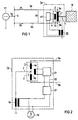
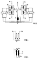
- Montage (1a, 1b, 1c) transformateur pour injecter une tension (Uz) supplémentaire dans une première ligne (9a) de transmission pour de l'énergie électrique, comportant un transformateur (4, 4a, 4b) supplémentaire qui peut être branché en série par au moins l'un de ses enroulements (3) avec la première ligne (9a) de transmission et qui est alimenté en énergie par l'intermédiaire d'un transformateur (15) excitateur dont l'enroulement (3) a une prise (7) médiane qui subdivise l'enroulement en deux sous-enroulements (5a, 5b),
caractérisé en ce que, pour relier la première ligne (9a) de transmission à une deuxième ligne (9b) de transmission, l'un (5a) des sous-enroulements peut être branché en série avec la première ligne (9a) de transmission et l'autre sous-enroulement (5a) peut être branché en série avec la deuxième ligne (9b) de transmission si bien que la prise (7) médiane forme un point (Y) nodal du réseau. - Montage transformateur suivant la revendication 1, caractérisé en ce qu'il est prévu une troisième et une quatrième lignes (9c, 9d) de transmission qui sont reliées l'une à l'autre également par l'intermédiaire de sous-enroulements associés d'un deuxième transformateur (4b) supplémentaire, les prises (7) médianes et deux transformateurs (4a, 4b) supplémentaires pouvant être reliées l'une à l'autre et formant un point (K) nodal du réseau.
- Montage transformateur suivant la revendication 2, caractérisé en ce que les deux transformateurs (4a, 4b) supplémentaires sont alimentés en énergie par l'intermédiaire du même transformateur (15) excitateur.
- Montage transformateur suivant la revendication 2, caractérisé en ce que les transformateurs (4a, 4b) supplémentaires sont alimentés en énergie par l'intermédiaire de transformateurs excitateurs distincts.
- Montage transformateur suivant l'une des revendications 1 à 4, caractérisé en ce que la/les prise(s) (7) médiane(s) peuvent être branchées au côté haute tension du/des transformateur(s) (15, 18) excitateur(s).
- Montage transformateur suivant l'une des revendications 1 à 5, caractérisé en ce que le transformateur excitateur sert de transformateur (18) rotatif, une génératrice (19) pouvant être raccordée à son enroulement (13) côté basse tension.
- Montage transformateur suivant l'une des revendications 1 à 7, en ce qu'il peut être branché respectivement un élément (17, 17a, 17b) de commande entre un transformateur (4, 4a, 4b) supplémentaire et un transformateur (15, 18) excitateur associé.
- Montage transformateur suivant la revendication 7, caractérisé en ce qu'un dispositif (21) mutateur sert d'élément (17, 17a, 17b) de commande.
- Montage transformateur suivant la revendication 8, caractérisé en ce que le montage (21) mutateur comporte un circuit (22) intermédiaire de courant continu.
- Montage transformateur suivant l'une des revendications 1 à 9, caractérisé en ce que le nombre de phases est égal au nombre de phases des lignes (9a à 9d) de transmission.
- Dispositif transformateur suivant l'une des revendications 1 à 10, caractérisé en ce que la/les prise(s) (7) médiane(s) est (sont) à environ 50 % du nombre total de spires de l'enroulement (3).
- Montage transformateur suivant l'une des revendications 1 à 10, caractérisé en ce que la prise (7) médiane est à environ 50 % du nombre total de spires de l'enroulement.
Applications Claiming Priority (3)
| Application Number | Priority Date | Filing Date | Title |
|---|---|---|---|
| DE1996112744 DE19612744C1 (de) | 1996-03-29 | 1996-03-29 | Transformatoranordnung |
| DE19612744 | 1996-03-29 | ||
| PCT/DE1997/000543 WO1997037419A1 (fr) | 1996-03-29 | 1997-03-17 | Montage transformateur |
Publications (2)
| Publication Number | Publication Date |
|---|---|
| EP0890212A1 EP0890212A1 (fr) | 1999-01-13 |
| EP0890212B1 true EP0890212B1 (fr) | 2002-07-03 |
Family
ID=7789983
Family Applications (1)
| Application Number | Title | Priority Date | Filing Date |
|---|---|---|---|
| EP19970916348 Expired - Lifetime EP0890212B1 (fr) | 1996-03-29 | 1997-03-17 | Montage transformateur |
Country Status (6)
| Country | Link |
|---|---|
| US (1) | US6194795B1 (fr) |
| EP (1) | EP0890212B1 (fr) |
| AT (1) | ATE220257T1 (fr) |
| CA (1) | CA2250112A1 (fr) |
| DE (2) | DE19612744C1 (fr) |
| WO (1) | WO1997037419A1 (fr) |
Families Citing this family (5)
| Publication number | Priority date | Publication date | Assignee | Title |
|---|---|---|---|---|
| DE19612744C1 (de) * | 1996-03-29 | 1997-11-13 | Siemens Ag | Transformatoranordnung |
| DE10056945C2 (de) | 2000-11-17 | 2003-08-21 | Epcos Ag | Ferritkern mit neuer Bauform, Überträger und Verwendung des Ferritkerns |
| JP3929767B2 (ja) * | 2001-12-14 | 2007-06-13 | 三菱電機株式会社 | 電力系統の横流補償制御システム |
| JP6075827B2 (ja) * | 2012-06-08 | 2017-02-08 | キヤノン株式会社 | スイッチング電源装置及び画像形成装置 |
| US10044187B2 (en) * | 2015-04-30 | 2018-08-07 | Abb Schweiz Ag | AC network power flow control |
Family Cites Families (7)
| Publication number | Priority date | Publication date | Assignee | Title |
|---|---|---|---|---|
| FR2541532A1 (fr) * | 1983-02-22 | 1984-08-24 | Gen Equipment Medical | Procede de commutation de l'alimentation electrique entre deux circuits de charge independants |
| EP0152002B1 (fr) * | 1984-02-10 | 1988-11-17 | BBC Brown Boveri AG | Déphaseur |
| US4626697A (en) * | 1984-10-22 | 1986-12-02 | American Hospital Supply Corporation | Power supply for providing plural DC voltages |
| JPH01144606A (ja) * | 1987-11-30 | 1989-06-06 | Nec Corp | オートトランス |
| ES2103129T3 (es) * | 1993-05-14 | 1997-08-16 | Citeq | Metodo de cambio de fase de los voltajes aplicados a componentes de circuito que interconectan dos redes de ca polifasicas sincronicas y un aparato de interconexion de cambio de fase al respecto. |
| DE4343929A1 (de) * | 1993-12-22 | 1995-06-29 | Siemens Ag | Verfahren zur Inbetriebnahme und zur Außerbetriebnahme eines Zusatztransformators |
| DE19612744C1 (de) * | 1996-03-29 | 1997-11-13 | Siemens Ag | Transformatoranordnung |
-
1996
- 1996-03-29 DE DE1996112744 patent/DE19612744C1/de not_active Expired - Fee Related
-
1997
- 1997-03-17 WO PCT/DE1997/000543 patent/WO1997037419A1/fr not_active Ceased
- 1997-03-17 AT AT97916348T patent/ATE220257T1/de not_active IP Right Cessation
- 1997-03-17 EP EP19970916348 patent/EP0890212B1/fr not_active Expired - Lifetime
- 1997-03-17 CA CA 2250112 patent/CA2250112A1/fr not_active Abandoned
- 1997-03-17 DE DE59707651T patent/DE59707651D1/de not_active Expired - Fee Related
-
1998
- 1998-09-25 US US09/160,869 patent/US6194795B1/en not_active Expired - Fee Related
Also Published As
| Publication number | Publication date |
|---|---|
| US6194795B1 (en) | 2001-02-27 |
| DE19612744C1 (de) | 1997-11-13 |
| WO1997037419A1 (fr) | 1997-10-09 |
| EP0890212A1 (fr) | 1999-01-13 |
| CA2250112A1 (fr) | 1997-10-09 |
| ATE220257T1 (de) | 2002-07-15 |
| DE59707651D1 (de) | 2002-08-08 |
Similar Documents
| Publication | Publication Date | Title |
|---|---|---|
| EP0152002B1 (fr) | Déphaseur | |
| WO2020079019A1 (fr) | Topologie de convertisseur statique polyphasée pour fonctionnement polyphasé et monophasé | |
| DE102012103048B4 (de) | Regeltransformatoren zur Spannungsregelung mit Halbleiter-Schaltelementen | |
| DE102019106485A1 (de) | Weissach-Gleichrichteranordnung | |
| EP2384606A1 (fr) | Dispositif de commande d'une pluralité de consommateurs électriques | |
| EP0890212B1 (fr) | Montage transformateur | |
| EP1638196A2 (fr) | Dispositif pour alimenter des charges variables | |
| EP3751692A1 (fr) | Station de transmission de courant continu à haute tension | |
| EP1446708A2 (fr) | Procede et dispositif de regulation de la tension electrique | |
| EP3069428B1 (fr) | Système de transmission à haute tension, en courant continu avec interrupteur de mise à terre | |
| WO2023217505A1 (fr) | Dispositif et procédé d'adaptation d'un angle de phase d'une tension dans une ligne de transmission | |
| EP4150753A1 (fr) | Onduleur photovoltaïque triphasé à fonctionnement isolé en 2 phases en cas de défaut de réseau | |
| DE641335C (de) | Einrichtung zum Betriebe elektrischer Netze | |
| WO2012065881A1 (fr) | Système redresseur de courant et système convertisseur comportant un système redresseur de ce type | |
| DE2753464A1 (de) | Einrichtung zur einstellung der spannung an transformatoren unter last | |
| DE882449C (de) | Gleichstromkraftuebertragungsanlage mit Stromrichtern an den Enden der UEbertragungsleitung | |
| AT406204B (de) | Transformator | |
| DE20318061U1 (de) | Schaltungsanordnung zur Versorgung von einer ungeraden Anzahl von parallel oder in Reihe geschalteten Lasten mit elektrischer Energie | |
| DE676591C (de) | Anordnung zur Beeinflussung des Leistungsfaktors von mit gittergesteuerten Dampf- oder Gasentladungsstrecken arbeitenden Umformungseinrichtungen | |
| DE623907C (de) | Einrichtung zur selbsttaetigen Ein- und Ausschaltung von Speiseleitungsschaltern in vermaschten Verteilungsnetzen | |
| WO2022112273A2 (fr) | Circuiterie et procédé de commande d'équipements électriques et/ou de parties de lignes de réseau | |
| DE588301C (de) | Schutzschaltung zur selbsttaetigen Steuerung der Schalter einer Leitungsstrecke | |
| DE19906457B4 (de) | Elektrische Energieübertragungsstrecke | |
| DE102023208670A1 (de) | Energietransfervorrichtung | |
| EP4654412A1 (fr) | Régulateur de débit de charge à plusieurs parties pour réseaux à tension continue |
Legal Events
| Date | Code | Title | Description |
|---|---|---|---|
| PUAI | Public reference made under article 153(3) epc to a published international application that has entered the european phase |
Free format text: ORIGINAL CODE: 0009012 |
|
| 17P | Request for examination filed |
Effective date: 19980917 |
|
| AK | Designated contracting states |
Kind code of ref document: A1 Designated state(s): AT DE SE |
|
| GRAG | Despatch of communication of intention to grant |
Free format text: ORIGINAL CODE: EPIDOS AGRA |
|
| 17Q | First examination report despatched |
Effective date: 20010504 |
|
| GRAG | Despatch of communication of intention to grant |
Free format text: ORIGINAL CODE: EPIDOS AGRA |
|
| GRAH | Despatch of communication of intention to grant a patent |
Free format text: ORIGINAL CODE: EPIDOS IGRA |
|
| GRAH | Despatch of communication of intention to grant a patent |
Free format text: ORIGINAL CODE: EPIDOS IGRA |
|
| GRAA | (expected) grant |
Free format text: ORIGINAL CODE: 0009210 |
|
| AK | Designated contracting states |
Kind code of ref document: B1 Designated state(s): AT DE SE |
|
| REF | Corresponds to: |
Ref document number: 220257 Country of ref document: AT Date of ref document: 20020715 Kind code of ref document: T |
|
| REF | Corresponds to: |
Ref document number: 59707651 Country of ref document: DE Date of ref document: 20020808 |
|
| PG25 | Lapsed in a contracting state [announced via postgrant information from national office to epo] |
Ref country code: SE Free format text: LAPSE BECAUSE OF FAILURE TO SUBMIT A TRANSLATION OF THE DESCRIPTION OR TO PAY THE FEE WITHIN THE PRESCRIBED TIME-LIMIT Effective date: 20021003 |
|
| PG25 | Lapsed in a contracting state [announced via postgrant information from national office to epo] |
Ref country code: AT Free format text: LAPSE BECAUSE OF NON-PAYMENT OF DUE FEES Effective date: 20030317 |
|
| PLBE | No opposition filed within time limit |
Free format text: ORIGINAL CODE: 0009261 |
|
| STAA | Information on the status of an ep patent application or granted ep patent |
Free format text: STATUS: NO OPPOSITION FILED WITHIN TIME LIMIT |
|
| 26N | No opposition filed |
Effective date: 20030404 |
|
| PG25 | Lapsed in a contracting state [announced via postgrant information from national office to epo] |
Ref country code: DE Free format text: LAPSE BECAUSE OF NON-PAYMENT OF DUE FEES Effective date: 20031001 |