EP0890214B1 - Machines a courant alternatif - Google Patents
Machines a courant alternatif Download PDFInfo
- Publication number
- EP0890214B1 EP0890214B1 EP97915581A EP97915581A EP0890214B1 EP 0890214 B1 EP0890214 B1 EP 0890214B1 EP 97915581 A EP97915581 A EP 97915581A EP 97915581 A EP97915581 A EP 97915581A EP 0890214 B1 EP0890214 B1 EP 0890214B1
- Authority
- EP
- European Patent Office
- Prior art keywords
- stator
- alternating current
- busbars
- machine according
- current machine
- Prior art date
- Legal status (The legal status is an assumption and is not a legal conclusion. Google has not performed a legal analysis and makes no representation as to the accuracy of the status listed.)
- Expired - Lifetime
Links
- 238000004804 winding Methods 0.000 claims abstract description 77
- 230000007935 neutral effect Effects 0.000 claims abstract description 25
- 239000004020 conductor Substances 0.000 claims description 17
- 238000001816 cooling Methods 0.000 claims description 10
- 238000009423 ventilation Methods 0.000 claims description 6
- 239000000463 material Substances 0.000 claims description 5
- 239000007787 solid Substances 0.000 claims description 5
- 239000004033 plastic Substances 0.000 claims description 4
- 229920003023 plastic Polymers 0.000 claims description 4
- 230000009471 action Effects 0.000 claims description 2
- 125000006850 spacer group Chemical group 0.000 claims description 2
- 230000004888 barrier function Effects 0.000 abstract description 4
- 239000011810 insulating material Substances 0.000 abstract description 3
- 238000000465 moulding Methods 0.000 description 9
- 230000008878 coupling Effects 0.000 description 6
- 238000010168 coupling process Methods 0.000 description 6
- 238000005859 coupling reaction Methods 0.000 description 6
- 230000005540 biological transmission Effects 0.000 description 4
- RYGMFSIKBFXOCR-UHFFFAOYSA-N Copper Chemical compound [Cu] RYGMFSIKBFXOCR-UHFFFAOYSA-N 0.000 description 3
- 239000004677 Nylon Substances 0.000 description 3
- 230000015572 biosynthetic process Effects 0.000 description 3
- 229910052802 copper Inorganic materials 0.000 description 3
- 239000010949 copper Substances 0.000 description 3
- 230000000694 effects Effects 0.000 description 3
- 238000005755 formation reaction Methods 0.000 description 3
- 239000011521 glass Substances 0.000 description 3
- 230000004048 modification Effects 0.000 description 3
- 238000012986 modification Methods 0.000 description 3
- 229920001778 nylon Polymers 0.000 description 3
- 239000011347 resin Substances 0.000 description 3
- 229920005989 resin Polymers 0.000 description 3
- 230000000717 retained effect Effects 0.000 description 3
- 229920000784 Nomex Polymers 0.000 description 2
- 230000005284 excitation Effects 0.000 description 2
- 238000009413 insulation Methods 0.000 description 2
- 229910052751 metal Inorganic materials 0.000 description 2
- 239000002184 metal Substances 0.000 description 2
- 239000004763 nomex Substances 0.000 description 2
- 229920000728 polyester Polymers 0.000 description 2
- 230000002459 sustained effect Effects 0.000 description 2
- 239000004593 Epoxy Substances 0.000 description 1
- ATJFFYVFTNAWJD-UHFFFAOYSA-N Tin Chemical compound [Sn] ATJFFYVFTNAWJD-UHFFFAOYSA-N 0.000 description 1
- 238000009954 braiding Methods 0.000 description 1
- 238000006243 chemical reaction Methods 0.000 description 1
- 238000010276 construction Methods 0.000 description 1
- ALKZAGKDWUSJED-UHFFFAOYSA-N dinuclear copper ion Chemical compound [Cu].[Cu] ALKZAGKDWUSJED-UHFFFAOYSA-N 0.000 description 1
- 238000006073 displacement reaction Methods 0.000 description 1
- 239000012777 electrically insulating material Substances 0.000 description 1
- 239000002320 enamel (paints) Substances 0.000 description 1
- 238000005470 impregnation Methods 0.000 description 1
- 230000006872 improvement Effects 0.000 description 1
- 230000006698 induction Effects 0.000 description 1
- 239000012212 insulator Substances 0.000 description 1
- 230000001788 irregular Effects 0.000 description 1
- 239000000203 mixture Substances 0.000 description 1
- 229920001187 thermosetting polymer Polymers 0.000 description 1
- 238000011144 upstream manufacturing Methods 0.000 description 1
Images





Classifications
-
- H—ELECTRICITY
- H02—GENERATION; CONVERSION OR DISTRIBUTION OF ELECTRIC POWER
- H02K—DYNAMO-ELECTRIC MACHINES
- H02K3/00—Details of windings
- H02K3/46—Fastening of windings on the stator or rotor structure
- H02K3/50—Fastening of winding heads, equalising connectors, or connections thereto
-
- H—ELECTRICITY
- H02—GENERATION; CONVERSION OR DISTRIBUTION OF ELECTRIC POWER
- H02K—DYNAMO-ELECTRIC MACHINES
- H02K5/00—Casings; Enclosures; Supports
- H02K5/04—Casings or enclosures characterised by the shape, form or construction thereof
- H02K5/20—Casings or enclosures characterised by the shape, form or construction thereof with channels or ducts for flow of cooling medium
- H02K5/207—Casings or enclosures characterised by the shape, form or construction thereof with channels or ducts for flow of cooling medium with openings in the casing specially adapted for ambient air
-
- H—ELECTRICITY
- H02—GENERATION; CONVERSION OR DISTRIBUTION OF ELECTRIC POWER
- H02K—DYNAMO-ELECTRIC MACHINES
- H02K5/00—Casings; Enclosures; Supports
- H02K5/04—Casings or enclosures characterised by the shape, form or construction thereof
- H02K5/22—Auxiliary parts of casings not covered by groups H02K5/06-H02K5/20, e.g. shaped to form connection boxes or terminal boxes
- H02K5/225—Terminal boxes or connection arrangements
-
- H—ELECTRICITY
- H02—GENERATION; CONVERSION OR DISTRIBUTION OF ELECTRIC POWER
- H02K—DYNAMO-ELECTRIC MACHINES
- H02K9/00—Arrangements for cooling or ventilating
- H02K9/02—Arrangements for cooling or ventilating by ambient air flowing through the machine
- H02K9/04—Arrangements for cooling or ventilating by ambient air flowing through the machine having means for generating a flow of cooling medium
- H02K9/06—Arrangements for cooling or ventilating by ambient air flowing through the machine having means for generating a flow of cooling medium with fans or impellers driven by the machine shaft
-
- H—ELECTRICITY
- H02—GENERATION; CONVERSION OR DISTRIBUTION OF ELECTRIC POWER
- H02K—DYNAMO-ELECTRIC MACHINES
- H02K2203/00—Specific aspects not provided for in the other groups of this subclass relating to the windings
- H02K2203/06—Machines characterised by the wiring leads, i.e. conducting wires for connecting the winding terminations
Definitions
- terminal leads are bunched together as a solid mass, problems with hot spots arise. Also difficulties arise which cause the terminals to which terminal leads are connected to be located well spaced from the axis of rotation of the rotor. In practice there is no insulation between those terminals and the annular array of stator windings of the machine as is shown in DE-A-1144382.
- US-A-5175458 discloses an assembly for carrying stator terminal leads to a terminator to which an electrical connection can be made.
- the alternator for which this assembly is designed is relatively small.
- the assembly comprises an arcuate, or horseshoe-shaped member which is fitted to the appropriate end of the stator.
- the horseshoe-shaped member is solid and has three circumferentially extending channels defined in its outer surface. Each channel receives a terminal lead which is an extension of a stator winding and leads that terminal lead along the circumferentially extending track it forms to the terminator to which it is connected.
- the channels are axially spaced from one another. This arrangement would suffer from cooling problems if it were to be used in large alternating current machines because the terminal leads would be shielded from cooling air flow through the stator.
- an alternating current machine as claimed in claim 1. Preferred features of that alternating current machine are claimed in claims 2 to 18.
- DE-A-1144382 illustrates an arrangement of output terminals of an alternating current machine to which stator winding terminal leads may be connected.
- Each terminal to which such a terminal lead is connected is supported by a metal angle member to which it is riveted.
- the angle members are spaced from one another and are mounted at either end on a support fixed to the casing through a respective insulator.
- FR-A-2693848 disclose a mounting for distribution busbars in which the busbars are clamped between elongate mouldings which fill spaces between faces of adjacent busbars.
- the mouldings have a uniform cross-section with flat sides which are in face to face abutment with the faces of the busbars. Gaps remain between the edges of adjacent busbars and adjacent mouldings since the mouldings are spaced from one another by the thickness of the busbars.
- the stack of mouldings and busbars is clamped by nuts fitted to the ends of screws which extend through the gaps and through aligned holes in the mouldings.
- the rotor of an alternating current machine may carry a fan at the end of the stator remote from the terminal leads.
- the fan would be operable to draw air through the stator from the remote end therof in order to cool the stator windings.
- DE-A-2526532 discloses such a rotor and fan arrangement.
- the fan is within a casing which cooperates with it to provide a conduit for discharge of air flow from the fan, the conduit being in the form of a volute whereby its area increases progressively in the downstream direction.
- a volute casing improves the cooling by increasing the volume of air that is drawn through the stator by the fan for discharge through the discharge passage formed by the volute casing, even more cooling is desirable.
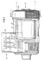
- FIGS 1 and 2 show an AC generator which comprises a casing 21.
- a casing 21 At the left hand of the casing 21, as seen in Figure 1, there is an output terminal block 22 by which a three phase alternating current generated by the AC generator is collected from armature windings 23 (see Figure 1) on a stator 24 which is housed within the casing 21.
- a rotor 25 is journalled in the stator 24.
- the rotor 25 carries a coupling plate 26 at its right hand end, as seen in Figure 1.
- the coupling plate 26 is for coupling to a fly-wheel of a prime mover or engine whereby the rotor 25 is driven.
- FIG. 3 shows the right hand end of the rotor 25 projecting from the right hand end of the stator 24.
- a radial flow fan 27 is bolted onto a hub 28 which is force fitted onto the end of the rotor 25 adjacent the coupling plate 26 which is fixed to it by set screws 29.
- the fan 27 may be forced fitted directly onto the rotor 25 instead.
- FIGS 3 and 4 show the fan 27 is surrounded by a volute casing 30 which is bolted to the end of the casing 21.
- the volute casing 30 is formed so that two diametrically opposed portions of it diverge in the downstream direction from the path traced by the tips of the blades 31 of the fan 27.
- two diametrically opposed passages 32 for the discharge of air from the fan 27 are formed between the fan 27 and the volute casing 30, the cross-sectional area of each of these discharge passages 32 increasing progressively in the discharge direction.
- Each blade 31 projects from the hub 28 at an angle which is oblique to the notional radius that passes through the root of that blade 31, each blade 31 diverging from its respective notional radius in a direction which is upstream with respect to air flow generated by the fan 27.
- the tip 33 of each blade 31 is tapered so that it converges with the axis of rotation, the angle of taper being of the order of 12.5 degrees and the taper being towards the coupling plate 26.
- FIG. 5 shows the stator 24 with the casing 21 and the rotor 25 removed.
- the stator windings 23 may be either perfect lap windings or perfect concentric windings as will be understood by a man skilled in the art.
- a circumferential array of cleats 35 project from the end of the stator core on which they are mounted.
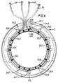
- Figure 6 shows that one of the cleats 35 is located at the top of the stator 24 and the others are equally spaced at angular intervals of about 30°.
- FIG. 7 shows an exemplary group of stator windings 23 at the end of the stator 24 from which the power output leads 34 are led to an output terminal block 22.
- Each winding 23 comprises a bunch of generally parallel wire conductors 36 which are led along generally parallel paths which run the length of the stator 24 from end to end and which are turned around at either end, so that a bunch of wire conductors 36 which emerges from one axially extending path in the stator 24 at one end of the stator 24 is turned around to re-enter a parallel axially extending path in the stator 24.
- windings 23 are a perfect lap winding arrangement so that each curved winding portion 37 by which the wire conductors 36 are so turned around overlap several of the adjacent curved winding portions 37 that are spaced from it in one circumferential direction around the stator 24, those being the other winding portions 37 that emerge from the stator 24 between its point of emergence from the stator 24 and its point of re-entry to the stator 52. Also, there are two bunches of conductors 36 laid one on the other in each parallel path in the stator 24. All the reentrant conductors 36 are laid over the other bunch of conductors 36 that they overlap, in the respective path. Each of these windings 23 has two ends which are extended outwards from the stator 24 to form the power output leads 34 by which the stator windings 23 are connected to the terminal block 22.
- Each cleat 35 is a moulding of an electrically insulating plastics material such as nylon.
- Figure 8 shows that each cleat 35 comprises an elongate back portion 39 from which seven prongs 41 project laterally so that it has the form of a comb.
- Each cleat 35 is mounted on the stator core with its back portion 39 extending axially with respect to the stator 24 and with the prongs 41 projecting radially outwardly.
- the prongs 41 are shaped so that the nearer sides of juxtaposed prongs 41 converge.
- each of the intervening spaces of each cleat 35 is thereby adapted to receive a lead 34 which is fitted into it with a snap action through its narrow mouth and which is retained in it by the prongs 37.
- Two spaced walls 42 project from the back portion 39 in the opposite direction to that in which the prongs 41 project, each side wall 42 extending from a respective one of the two longitudinally extending edges of the back portion 39.
- the spacing between the two side walls 42 is bridged at one end of the cleat 35 by a flat plate-like element 43 at the ends of the side walls 42 remote from the back portion 39, the plate-like element 43 projecting from the end of the side walls 42 to form a projecting tongue 44.
- the space between the side walls 42 is also bridged by another short plate-like portion 45 at a location which is about three-quarters of the length of the cleat 35 from the plate-like element 43.
- the thickness of the plate-like portion 45 increases progressively in the direction away from the plate-like element 43, flaring outwardly from the back portion 39 to the end which is remote from the plate-like element 43.
- each prong 41 has a rectangular recess 46 formed in it substantially centrally.
- the recesses 46 in each prong 41 are aligned.
- Each cleat 35 is provided with a respective strap 47 by which it is fastened to the adjacent group of curved stator winding portions 37.
- the strap 47 has a rectangular cross-section and is provided at one end with a ring portion 48 which serves as a retaining socket, the aperture of the socket having a similar form, it being for receiving the other end of the strap 47.
- One of the sides of the strap 47 is provided with formations which engage in a corresponding formation in the inner periphery of the ring portion 48 whereby the length of strap 47 threaded through the aperture of the ring portion 48 is retained therein against being pulled back.
- the strap 47 is laid in the recesses 46 at the ends of the prongs 41 so that it projects from either end of the cleat 35, the ring portion 48 being to the left as seen in Figure 8.
- the ring portion 48 is threaded into the channel between the side walls 42 and through the gap between the back portion 39 and the plate-like element 43. From there it is drawn through the gap between the plate-like element 43 and the plate-like portion 45 and passed around the plate-like portion 45 to the other end of the cleat 35 where it is fitted over the other end of the strap 47 which protrudes from the cleat 35 so as to complete a loop formed by the strap 47 which surrounds the cleat 35.
- the flared plate-like portion 45 rests upon the adjacent curved stator winding portion 37 and the tongue 44 locates against the end of the stator 24.
- the curved winding portions 37 that are below the cleat 35 are encircled by the strap 47 so that they are trapped between the strap 47 and the lower edges of the side walls 42 of the cleat 35 whereby the cleat 35 is fastened to them.
- the length of the strap 47 which is laid within the recesses 46 in the prongs 41 serves to brace leads 34 within the respective intervening spaces between juxtaposed prongs 41 through which they are led from the stator windings 23 to the terminal block 22 to resist electromagnetic forces, which would otherwise tend to displace them, especially under fault conditions, such as sudden or sustained short circuit faults, externally imposed on the alternator by the power transmission or distribution system to which it may be connected.
- the prongs also serve as spacers which space juxtaposed terminal leads 34 apart and react electromagnetic forces which act to urge towards them the leads 34 that they separate.
- the strap 47 is a moulding of electrically insulating plastics material such as nylon.
- the six radially outwardly tapered spaces formed between the prongs 41 of each of the cleats 35 are arranged as a circumferentially spaced series and thereby define six juxtaposed circumferential tracks for the leads 34 by which those leads 34 are guided from the stator 24 to a location to one side of and above the stator 24 at which they terminate as an array of twenty four upwardly projecting terminals 49.
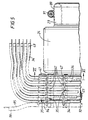
- Figures 1, 5 and 6 show that the leads 34 are spaced from one another in the direction of the axis of the stator 24 as they are led side by side around the six circumferentially extending tracks formed by the cleats 35.
- the linking together of the circumferential array of cleats 35 by the leads 34 into the grid structure provides additional strength to resist the effect of electromagnetic forces which, as previously described, would tend to displace the leads 34 and the protruding windings 23 under fault conditions, and thus augments the resistance to such electromagnetic forces provided by the straps 47 of each individual cleat 35 of the array.
- Figure 6 shows the arrangement of the four leads 34A and B and 34C and D that are led around an exemplary one of the circumferentially extending tracks, that being the track that is formed by those spaces of the cleats 35 that are nearest to the stator 24.
- the lead 34A extends axially from the stator 24 at a location which is spaced angularly from the top of the stator 24 by a few ° so that it is just to the right of the cleat 35T at the top, as seen in Figure 6. From there it is bent towards and snap-fitted into that cleat 35T from which it is bent upwards to its terminal 49.
- the lead 34B which is the other of the respective pair of leads 34 that are extensions of the opposite ends of a respective one of the stator windings 23, extends axially from the stator 24 at a location which is spaced angularly from the bottom of the stator 24 by about 25°. It is bent towards and snap-fitted into the respective space in the cleat 35A that is spaced from the bottom of the stator 24 by 30° and to the right as seen in Figure 6. The lead 34B is then snap-fitted into the respective space in each of the other four cleats 35B-35E on the same side of the stator 24 and finally it is snap-fitted into the cleat 35T above the lead 34A as can be seen from Figure 6. The lead 34B is then bent upwards to its terminal 49 alongside the lead 34A.
- the lead 34C emerges axially just to the left of the bottom cleat 35L. This is bent towards and snap-fitted into the respective space in the cleat 35F that is spaced from the bottom of the stator 24 by 25° and to the left as seen in Figure 6. It is then snap-fitted into the corresponding space in each of the other four cleats 35G to 35K on the same side of the stator 24.
- the other lead 34D of the respective pair emerges axially from the stator 24 just to the right of the cleat 35K. The two leads 34C and 34D are then bent together upwards to their respective terminals 49 alongside the pair of leads 34A and 34B.
- each of the six tracks leads a respective group of two pairs of leads 34 so that they extend upwardly to their terminals 49 in a manner similar to that described above with reference to Figure 6.
- Cleats having only four spaces instead of the six described and illustrated for the cleats 35 are used in single phase AC generators of otherwise similar design.
- Figures 9 and 10 show that the terminal block 22 comprises a structural panel 51.
- This panel 51 is formed of six similar elongate angle members 52A to 52F which are arranged in three juxtaposed pairs.
- the upright faces 53A and 53B, 53C and 53D, 53E and 53F, are abutting and the adjacent edges of the horizontal sides of juxtaposed angle members 52A to 52F are also abutting so that the six angle members 52A to 52F present a substantially continuous uninterrupted surface at the bottom of the terminal block 22.
- Each pair of abutting faces 53A-53F of each pair of angle members 52A and 52B, 52C and 52D, 52E and 52F have opposed grooves 54 and 55 formed in them running substantially vertically from the top to the bottom.
- each of those abutting faces 53A-53F There are four such grooves 54 and 55 formed in each of those abutting faces 53A-53F. They are spaced apart along the length of the respective angle members 52A to 52F to the same extent.
- the outer pair 54 of these four grooves are each about twice as long as each of the inner pair 55 of those grooves.
- Each opposed pair of grooves 54 and 55 in the abutting faces 53A-53F forms a rectangular section through passage running between the top and the bottom of the abutting vertical faces 53A-53F of the abutting angle members 52A-52F.
- Each such a through passage receives a respective busbar 56-58, 61-69 which is a close fit therein.
- the twelve busbars 56-58, 61-69 depend below the panel 51 spaced one from another, as can be seen in Figure 11, and each provides a terminal connection to which a respective terminal 49 of the leads 34 from the stator windings 23 is connected.
- Each of these busbars 56-58, 61-69 also projects above the panel 51.
- Each of the angle members 52 is formed from an insulating structural plastics material, such as nylon, by moulding.
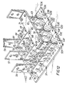
- the three busbars, 61-63, of the other group that extend through the three right hand larger through passages 54, as seen in Figures 11 and 12 are bent over at 90° above the panel 51 and are each connected to a common busbar 71 which provides the neutral output terminal of the AC generator.
- the two further groups of three separate busbars 64-66 and 67-69 that are provided between the three busbars 56-58 which serve as the three output terminals U, V and W and the other three busbars 61-63 that are connected together to the neutral output terminal 71, are spaced from each other and from those other busbars 56-58, 61-63 so as to be electrically insulated therefrom by the electrically insulating material of the structural panel 51.
- Each of the busbars 64-69 is located within a respective rectangular through passage which is formed by appropriate ones of the smaller grooves 55 in the abutting faces 53 of the angle members 52.
- Each of these two groups of three additional busbars 64-66, 67-69 is in line with a respective one of the output terminals U, V and W and the aligned busbar 61-63 that is connected to the neutral output terminal 71.
- the twelve busbars 56-58, 63-69 are arranged in four columns and in three rows.
- each of the pairs of busbars 64 and 67, 65 and 68, 66 and 69 between a respective one of the three output terminals U, V and W and a respective one of the busbars 61-63 which is connected to the neutral output terminal 71, is connected together by a respective connecting link 72-74.
- connecting links 72-74 are removed and replaced by separate connecting links 75 and 76, 77 and 78, 81 and 82 which are shown chain dotted in Figure 12 and by which each of the busbars 64-69 that is between a power output terminal U, V, W and the respective busbar 61-63 that is connected to the neutral output terminal 71 is itself connected by a respective connecting link 75-78, 81, 82 to the adjacent one of the respective power output terminals U, V, W or the neutral terminal busbar 61-63 as can be seen from Figure 12.
- connection arrangement can be changed from one to the other by working from above the structural panel 51 and there is no need to provide for access to the connections of the leads 34 to the busbars below the structural panel, which may therefore be permanent.
- a terminal block 22 which supports the electrical connections between the leads 34 and the output terminals U,V,W of the AC generator which is light in weight and which presents a substantially uninterrupted and electrically insulating barrier between the working area above those terminals U,V,W and the area within the casing 21 below the terminal block 22 such that there is a minimal risk of tools or debris being dropped or falling unintentionally into the AC generator during assembly or refurbishing.
- connection of the generator can be altered between series star and parallel star simply by changing over connections above that electrically insulating barrier.
- the construction of the terminal block 22 whereby it comprises six angle members 52 arranged side by side with upright faces 53 of adjacent angle members 52 abutting one another and adjacent edges of horizontal sides of those angle members 52 abutting one another as well, to form the substantially uninterrupted barrier, leads to the resultant panel 51 being a rigid formation.
- FIG. 13 shows armature windings which comprise twelve sets 83.1-83.12 of perfect concentric windings.
- Each set 83.1-83.12 of perfect concentric windings comprises a single conductor which is bent into four loops, one within another so that the four loops can lie substantially in the same plane, each loop being generally rectangular.
- each loop of a set of windings 83.1-83.12 are laid in a respective axially-extending slot 84 (see Figure 14) formed in the inner cylindrical surface of the stator 24 and extend beyond the stator 24 at either end so that the shorter sides of each loop of the stator windings overhang the stator 24 at the respective end.
- the four long sides 36 of the loops of each set 83.1-83.12 that lead in the clockwise sense, with respect to the other side of that set 83.1-83.12, are laid over the trailing long sides 36 of the next but one set 83.1-83.12 in the clockwise direction. This is so for each and everyone of the twelve sets 83.1-83.12 and is a characterising feature of perfect windings.
- Each winding set 83.1-83.12 has two output leads 34, one being a neutral lead and the other being a positive output lead.
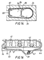
- Fig.14 shows that each stator slot 84 within which one long side 36 of a loop of a "perfect" concentric winding set 83.1-83.12 is laid upon another, is lined by an insulation 85. Also a Nomex shoe 86 is provided between the two loop side conductors 36 laid one on the other in the slot 84. Another such shoe 87 of insulating material, a Nomex polyester mixture, is laid on the one of those conductors 36 that is nearer the mouth of the slot 84. The latter is narrower than the remainder of the slot 84 and an epoxy glass board 88, which is wider than the mouth, closes that mouth so as to retain the shoes 86 and 87 and the conductors 36 within the slot 84.
- the right hand end of the stator 24, as seen in Fig.1, is known as the "Drive End”.
- the overhanging ends of the sets of windings 83.1-83.12 at the "Drive End” comprise the closed ends of all the loops of the twelve sets 83.1-83.12 of windings at the ends of those sets 83.1-83.12 remote from the terminal leads 34 and together comprise a circumferentially-extending annular array of windings 23.
- This circumferential array is encased in a wide mesh net 89 of lacing cord (as shown in Fig.) and is embraced around its outer surface by an encircling bracing rope 91.
- the bracing rope 91 comprises an inner core of pre-stressed linear mono-glass filaments within a woven outer sheath formed by braiding and impregnated with a thermosetting resin after assembly to comprise a rigid ring which restrains the winding array against displacement that may otherwise be caused in reaction to electromagnetic forces induced in the overhanging windings at that end of the stator 24 by high fault levels that may occur in a power transmission or distribution system into which the AC generator is installed.
- the prestressed linear mono-glass filaments encased in the outer sheath of braided polyester fibres is sufficiently flexible prior to impregnation with the insulating resin, for it to be wrapped around the overhanging portions of the windings 23 so that it closely conforms to the irregular shape of that overhanging portion, it being moulded into a rigid ring body having that form after the resin has set.
- the circumferential array of windings 23 at the "Non Drive End” is encased in a wide mesh net of lacing cord and is embraced at its end that is spaced from the stator 24 by a bracing rope 92.
- the bracing rope 92 is disposed radially inwardly with respect to the cleats 35 because of the presence of the latter. otherwise it is formed in substantially the same manner as has been described above for the bracing rope 91 at the "Drive End” .
- the coupling plate 26 is coupled to a fly-wheel of a driving prime mover or engine.
- its rotor windings are energised either by a direct current supply which is supplied to those windings via terminals on the rotor 25 through brushes and slip rings or, in the case of a brushless AC generator, by a rectified output of a separate small excitor which is usually mounted on the same shaft as the rotor 25.
- the latter has a DC stator winding and a 3-phase or single phase winding on its rotor, the output of which is rectified and fed to the windings on the rotor 25.
- This excitation current whether it is a separate DC supply or a rectified output of an exciter is a current of lower strength than the output of the AC generator.
- the driving prime motor is actuated to rotate the rotor 25 within the stator 24.
- the output current is generated in the stator windings 23 by mutual induction in the usual way and is led through the leads 34 to the terminals U, V, W of the terminal block.
- the fan 27 rotates with the rotor 25, draws air through the stator 24 from the remote end thereof and discharges that air through the discharge passages 32 formed by the volute casing 30.
- Use of the volute casing 30 improves the cooling by increasing the volume of air that is drawn through the stator 24 by the fan 27 for discharge through the discharge passages 32 formed by the volute casing 30.
- the arrangement of the blades 31 whereby they are oblique to the radial so that they trail the radial contributes to this arrangement.
- the tapering of the tips of the blades 31 leads to a lower noise output than has been found to be the case where the blades had tips which were substantially parallel to the axis of rotation.
- the air that is drawn through the stator 24 by the fan 27 is also drawn into the stator 24 around and through the leads 34 that are led around the six axially spaced circumferentially extending tracks formed by the circumferential array of cleats 35, those leads 34 being supported in free space by the cleats 35 with which they cooperate to form a grid structure as has been described above, the interstices of that grid structure serving as ventilation spaces through which that air is drawn. This enhances the ventilation of those leads 34 and further improves the cooling of the AC generator.
- the arrangement of the terminal block 22 results in the physical support for the metal busbars 56-59, 64-69 which conveniently are formed of a tin plated copper, being provided by the insulating material which is considerably more light weight than the conventional welded structure.
- Figures 15 and 16 show a modification of the AC generator described above with reference to Figures 1 to 14. Parts of the generator shown in Figures 15 and 16 which are similar to corresponding parts of the generator shown in Figures 1 to 14 are identified by the same reference characters. The generator shown in Figures 15 and 16 has "perfect" concentric windings 83 as have been described above with reference to Figures 13 and 14.
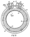
- Fig. 15 shows a circumferential array of six cleats 93 which are mounted on the curved winding portions that comprise the ends of the twelve sets 83.1-83.12 of winding portions that project from the "Non Drive End" of the stator 24.
- Fig. 16 shows that each of those cleats 93 is similar to the cleat 35 that has been described above with reference to and as shown in Fig. 8, except that the back portion 39 of the cleat 93 projects axially beyond the prongs 41 at the end thereof remote from the tongue 44 to form a shoulder 94 with the prong 41 that is furthest from the tongue 44.
- each of the circumferential array of cleats 93 provides a seat for a solid ring 95 of copper (shown chain dotted in Fig.5) which rests thereon whereby the ring 95 is supported by the circumferential array of cleats 93.
- the ring 95 is not a complete circle but extends over about 350 , the spaced ends of the resultant loop being at the top.
- Each of the neutral leads of the windings 23 is electrically connected to the ring 95 so supported on the annular array of cleats 93. To ensure a good electrical connection, the end of each such neutral lead is bared by removing the enamel coating to expose copper whereby to provide a good copper-copper contact.
- the ring 95 is retained upon its seat on each cleat 93 by the strap 47 that is passed around it.
- Each of the depending portions of the six narrower busbars 64-69 shown in Fig.11 and each of the load output terminals 56-58 has a respective pair of the positive output leads 34 connected to it.
- Two neutral connectors 96 and 97 are connected to one of the depending portions of the neutral busbars 61-63 (indeed the neutral busbars 61-63 may be arranged so that only one of them depends below the panel 51).
- Each of those neutral connectors 96 and 97 is connected to a respective end of the open loop that comprises the solid ring 95.
Landscapes
- Engineering & Computer Science (AREA)
- Power Engineering (AREA)
- Insulation, Fastening Of Motor, Generator Windings (AREA)
- Motor Or Generator Frames (AREA)
- Motor Or Generator Cooling System (AREA)
- Windings For Motors And Generators (AREA)
Abstract
Claims (18)
- Machine à courant alternatif comprenant un rotor (25) monté en rotation à l'intérieur d'un stator (24) comprenant des enroulements de stator (23), qui sont rassemblés en un agencement annulaire à une extrémité du stator (24), les enroulements de stator (23) ayant des fils de connexion (34) qui sont guidés autour de chemins respectifs, s'étendant dans la direction circonférentielle, et accouplés à des moyens de connexion (22), plusieurs de ces chemins s'étendant dans la direction circonférentielle étant prévus, chacun étant placé à une certaine distance axiale des autres chemins par rapport au stator (24), caractérisé en ce qu'un agencement circonférentiel de moyens de support et de guidage (35) est prévu à ladite extrémité du stator (24) pour guider lesdits fils de connexion (34) autour desdits chemins, les moyens de support et de guidage (35) étant espacés les uns des autres dans la direction circonférentielle, de telle sorte que lesdits fils de connexion (34) ainsi supportés et guidés s'étendent entre eux, dans des espaces libres, et des écartements de ventilation sont formés entre des fils de connexion (34) et des moyens de support et de guidage (35) contigus, ce qui augmente le refroidissement des fils de connexion (34) grâce à l'écoulement d'air à travers ces écartements de ventilation.
- Machine à courant alternatif selon la revendication 1, dans laquelle chacun des moyens de support et de guidage (35) dudit agencement comprend un élément orienté dans la direction axiale, qui est formé de matériaux plastiques isolants de l'électricité et qui peut être utilisé pour guider les faisceaux discrets côte à côte le long des chemins respectifs, entre les éléments contigus de l'agencement.
- Machine à courant alternatif selon la revendication 2, dans laquelle chaque élément (35) comprend une partie arrière allongée (39) ayant des dents (41) solidaires, qui en font saillie dans la direction latérale, de façon à avoir la forme d'un peigne, les dents (41) faisant saillie vers l'extérieur par rapport à l'axe du stator (24) et servant d'entretoises qui écartent les uns des autres les fils de connexion (34) qui sont juxtaposés, et qui exercent des forces électromagnétiques agissant de façon à pousser l'un vers l'autre, l'un ou l'autre des fils de connexion (34) qu'ils séparent.
- Machine à courant alternatif selon la revendication 3, dans laquelle les dents (40) sont configurées de telle sorte que les côtés les plus proches des dents juxtaposées (41) convergent vers les extrémités des dents (41) qui sont éloignées de la partie arrière (39), les embouchures formées entre ces extrémités des paires de dents (41) juxtaposées étant dimensionnées de telle sorte qu'un fil de connexion (34) puisse être installé dans les espaces intermédiaires entre chaque paire de dents (41) juxtaposées par une action d'encliquetage.
- Machine à courant alternatif selon la revendication 3 ou la revendication 4, dans laquelle chaque élément (35) est pourvu de moyens (47) montés aux extrémités de ses dents (41) pour y enserrer les fils (34).
- Machine à courant alternatif selon la revendication 5, dans laquelle lesdits moyens qui peuvent être utilisés pour enserrer les fils (34) dans chaque élément (35) sont une partie d'un long élément du type jonc flexible (47) qui, en plus de servir à enserrer les fils (34) dans l'élément (35) correspondant, comprend également une partie d'attache, qui est passée sous la partie arrière (39) de l'élément correspondant, à distance des dents (41), et sous des faisceaux de conducteurs (36) qui comprennent des parties des enroulements de stator (23) qui ont été enroulées au niveau de ladite extrémité du stator (24), ce en conséquence de quoi l'élément (35) correspondant est attaché aux enroulements de stator (23) par la partie d'attache (47).
- Machine à courant alternatif selon l'une quelconque des revendications 1 à 6, dans laquelle le rotor (25) est accouplé à un ventilateur (27) pour une rotation conjointe, le ventilateur (27) étant disposé à l'intérieur d'un carter (30) et pouvant être actionné pour provoquer un écoulement d'air à travers le stator (24), depuis ladite extrémité, cet écoulement d'air étant aspiré dans le stator (24) à travers les écartements de ventilation formés entre les fils de connexion (34) juxtaposés et les moyens de support et de guidage (35) contigus, au niveau de ladite extrémité du stator (24), le carter (30) coopérant avec le ventilateur (27) pour réaliser un conduit (32) servant évacuer l'écoulement d'air du ventilateur (27), le conduit (32) se présentant sous la forme d'une volute grâce à laquelle son aire augmente progressivement vers l'aval, le ventilateur (27) étant un ventilateur à écoulement radial qui présente des pales (31) faisant saillie du moyeu (28) suivant un angle oblique par rapport à la direction radiale, ce en conséquence de quoi ces pales (31) déplacent l'air dans la direction radiale.
- Machine à courant alternatif selon la revendication 7, dans laquelle le bout (33) de chaque pale (31) est incliné par rapport à l'axe de rotation du ventilateur (27), ce en conséquence de quoi il diverge de la paroi du carter environnant (30) dans la direction qui est parallèle à l'axe de rotation et qui s'écarte de ladite extrémité du stator (24).
- Machine à courant alternatif selon l'une quelconque des revendications 1 à 8, dans laquelle lesdits moyens de connexion (22) comprennent un panneau structurel (51) constitué d'un matériau structurel isolant de l'électricité, des barres omnibus (56-58, 61-69) qui s'étendent à travers le panneau (51) et qui sont supportées par ce dernier, avec un jeu minimal autour d'elles, les barres omnibus (56-58, 61-69) ayant des bornes de connexion formées à l'une de leurs extrémités, lesdits fils de connexion (34) étant connectés aux bornes des barres omnibus qui se trouvent du même côté du panneau (51) que les enroulements de stator (23), l'agencement étant tel que le panneau (51) ferme essentiellement le voisinage des barres omnibus (56-58, 61-69) autour desquelles il est ajusté serré.
- Machine à courant alternatif selon la revendication 9, dans laquelle le panneau structurel (51) comprend de longs éléments de butée juxtaposés (52).
- Machine à courant alternatif selon la revendication 10, dans laquelle chaque long élément est un élément incliné (52), des parties verticales des éléments inclinés juxtaposés (52) étant en butée, les unes en face des autres, avec les barres omnibus (56-58, 61-69) prises en sandwich entre elles, et les autres bords des éléments inclinés (52) étant également en butée, chaque barre omnibus (56-58, 61-69) s'étendant à travers un évidement (54, 55) correspondant formé dans l'une des faces en butée (53) des éléments inclinés juxtaposés (52).
- Machine à courant alternatif selon l'une quelconque des revendications 9 à 11, dans laquelle les barres omnibus (56-58, 61-69) comprennent trois barres omnibus de puissance (56-58) et, pour chacune de ces barres omnibus de puissance (56-58), une barre omnibus de neutre correspondante (61-63) et une paire de barres omnibus espacées (64&67, 65&68, 66&69), qui sont placées entre les barres omnibus de puissance et de neutre (56-58 et 61-63) respectives, desquelles elles sont espacées, et des moyens de liaison (72-78, 81, 82) pouvant être utilisés de manière sélective pour connecter ensemble lesdites paires de barres omnibus espacées (64&67, 65&68, 66&69) pour une connexion étoile en série, ou pour connecter une barre omnibus (64-69) de chacune desdites paires (64&67, 65&68, 66&69) à celle desdites barres omnibus de puissance et de neutre (56-58 et 61-63) qui est contiguë et connecter l'autre barre omnibus (64-69) de chacune desdites paires (64&67, 65&68, 66&69) à l'autre desdites barres omnibus de puissance et de neutre (56-58, 61-63) pour une connexion étoile en parallèle, lesdites connexions par lesdits moyens de liaison (72-78, 81, 82) étant effectuées sur le côté dudit panneau structurel (51) qui est opposé aux extrémités des barres omnibus (56-58, 61-69) auxquelles lesdits fils de connexion (34) sont connectés.
- Machine à courant alternatif selon l'une quelconque des revendications 1 à 12, dans laquelle les fils de connexion au neutre sont connectés à un anneau plein (95) constitué d'un matériau bon conducteur de l'électricité et qui est, quant à lui, connecté auxdits moyens de connexion (22).
- Machine à courant alternatif selon la revendication 13, lorsqu'elle dépend de la revendication 9, dans laquelle ledit anneau (95) est connecté à une barre omnibus de neutre (61-63) en dessous dudit panneau (51).
- Machine à courant alternatif selon la revendication 13 ou la revendication 14, dans laquelle ledit anneau (95) a des extrémités ouvertes et ses deux extrémités sont connectées à ladite barre omnibus de neutre (61-63) par des moyens de connexions respectifs (96, 97).
- Machine à courant alternatif selon l'une quelconque des revendications 13 à 15, dans laquelle ledit anneau (95) est supporté par lesdits moyens de support ou de guidage (35).
- Machine à courant alternatif selon la revendication 16, lorsqu'elle dépend de la revendication 3, dans laquelle ledit anneau (95) est supporté en contact avec celle desdites dents (41) de chacun desdits éléments (35) qui est la plus éloignée du stator (24).
- Machine à courant alternatif selon la revendication 17, lorsqu'elle dépend de la revendication 6, dans laquelle ledit anneau (95) est maintenu de façon à être supporté en contact avec ladite dent (41) de chacun desdits éléments (35), par le long élément du type jonc flexible (47) correspondant, par lequel cet élément (35) est attaché aux enroulements de stator (23).
Priority Applications (2)
| Application Number | Priority Date | Filing Date | Title |
|---|---|---|---|
| EP00117897A EP1081828A3 (fr) | 1996-03-29 | 1997-04-01 | Machine à courant alternatif |
| EP00117896A EP1077521A3 (fr) | 1996-03-29 | 1997-04-01 | Dispositifs de raccordement |
Applications Claiming Priority (7)
| Application Number | Priority Date | Filing Date | Title |
|---|---|---|---|
| GBGB9606679.0A GB9606679D0 (en) | 1996-03-29 | 1996-03-29 | Alternating current machines |
| GB9606679 | 1996-03-29 | ||
| GBGB9702666.0A GB9702666D0 (en) | 1997-02-10 | 1997-02-10 | Alternating current machines |
| GB9702666 | 1997-02-10 | ||
| GB9705649 | 1997-03-20 | ||
| GBGB9705649.3A GB9705649D0 (en) | 1997-03-20 | 1997-03-20 | Alternating current machines |
| PCT/GB1997/000931 WO1997037421A1 (fr) | 1996-03-29 | 1997-04-01 | Machines a courant alternatif |
Related Child Applications (2)
| Application Number | Title | Priority Date | Filing Date |
|---|---|---|---|
| EP00117896A Division EP1077521A3 (fr) | 1996-03-29 | 1997-04-01 | Dispositifs de raccordement |
| EP00117897A Division EP1081828A3 (fr) | 1996-03-29 | 1997-04-01 | Machine à courant alternatif |
Publications (2)
| Publication Number | Publication Date |
|---|---|
| EP0890214A1 EP0890214A1 (fr) | 1999-01-13 |
| EP0890214B1 true EP0890214B1 (fr) | 2001-08-01 |
Family
ID=27268213
Family Applications (3)
| Application Number | Title | Priority Date | Filing Date |
|---|---|---|---|
| EP97915581A Expired - Lifetime EP0890214B1 (fr) | 1996-03-29 | 1997-04-01 | Machines a courant alternatif |
| EP00117897A Withdrawn EP1081828A3 (fr) | 1996-03-29 | 1997-04-01 | Machine à courant alternatif |
| EP00117896A Withdrawn EP1077521A3 (fr) | 1996-03-29 | 1997-04-01 | Dispositifs de raccordement |
Family Applications After (2)
| Application Number | Title | Priority Date | Filing Date |
|---|---|---|---|
| EP00117897A Withdrawn EP1081828A3 (fr) | 1996-03-29 | 1997-04-01 | Machine à courant alternatif |
| EP00117896A Withdrawn EP1077521A3 (fr) | 1996-03-29 | 1997-04-01 | Dispositifs de raccordement |
Country Status (7)
| Country | Link |
|---|---|
| US (2) | US6271608B1 (fr) |
| EP (3) | EP0890214B1 (fr) |
| CN (1) | CN1244310A (fr) |
| AU (1) | AU2300997A (fr) |
| DE (1) | DE69705939T2 (fr) |
| ES (1) | ES2159129T3 (fr) |
| WO (1) | WO1997037421A1 (fr) |
Families Citing this family (39)
| Publication number | Priority date | Publication date | Assignee | Title |
|---|---|---|---|---|
| DE19752632A1 (de) * | 1997-11-27 | 1999-06-02 | Bitzer Kuehlmaschinenbau Gmbh | Kältemittelkompressor |
| JP3374776B2 (ja) * | 1999-02-05 | 2003-02-10 | 株式会社デンソー | 車両用交流発電機 |
| US7522878B2 (en) | 1999-06-21 | 2009-04-21 | Access Business Group International Llc | Adaptive inductive power supply with communication |
| JP2002199644A (ja) * | 2000-12-28 | 2002-07-12 | Aisin Aw Co Ltd | 3相モータ |
| KR100459144B1 (ko) * | 2002-02-08 | 2004-12-03 | 엘지전자 주식회사 | 세탁기용 아우터 로터형 유도전동기 |
| JP3681366B2 (ja) * | 2002-08-21 | 2005-08-10 | 日立電線株式会社 | 配電部品及びその製造方法 |
| US6933638B2 (en) * | 2003-10-30 | 2005-08-23 | A. O. Smith Corporation | Electric motor having a reverse air flow cooling system |
| US7291950B2 (en) | 2004-01-14 | 2007-11-06 | Mitsubishi Denki Kabushiki Kaisha | Electric rotating machine for vehicle |
| FR2865079B1 (fr) | 2004-01-14 | 2014-09-05 | Mitsubishi Electric Corp | Machine electrique tournante pour vehicule |
| DE102004002032A1 (de) * | 2004-01-14 | 2005-08-04 | Mitsubishi Denki K.K. | Elektrische Rotationsmaschine für ein Kraftfahrzeug |
| JP2005229755A (ja) * | 2004-02-13 | 2005-08-25 | Toyota Motor Corp | モータモジュール |
| US7002271B2 (en) * | 2004-03-22 | 2006-02-21 | General Motors Corporation | Wiring connection module for hybrid electro-mechanical transmission |
| JP4662200B2 (ja) * | 2004-09-29 | 2011-03-30 | 日本電産株式会社 | モータおよびブスバー |
| DE102005023363A1 (de) * | 2005-05-20 | 2006-11-23 | Robert Bosch Gmbh | Fünfphasiger Generator |
| JP4287418B2 (ja) * | 2005-09-02 | 2009-07-01 | 本田技研工業株式会社 | モータの結線構造 |
| US20080006045A1 (en) * | 2006-07-05 | 2008-01-10 | Scs Frigette | System, method, and apparatus for providing auxiliary power, heating, and air conditioning for a vehicle |
| US7495353B2 (en) * | 2006-08-01 | 2009-02-24 | Hamilton Sundstrand Corporation | Power interconnect block for an aircraft electrical component |
| DE502007007114D1 (de) * | 2007-03-10 | 2011-06-16 | Abm Greiffenberger Antriebstechnik Gmbh | Klemmbrett sowie elektrische Maschine |
| US7872385B2 (en) * | 2007-07-27 | 2011-01-18 | GM Global Technology Operations LLC | Electric motor power connection assembly |
| US20100213775A1 (en) * | 2009-02-24 | 2010-08-26 | C.E. Niehoff & Co. | High power density generator |
| JP5278546B2 (ja) * | 2009-12-18 | 2013-09-04 | トヨタ自動車株式会社 | ステータ |
| US8446058B2 (en) * | 2010-09-20 | 2013-05-21 | General Electric Company | Electric motor terminal block assembly |
| JP5875886B2 (ja) * | 2012-02-08 | 2016-03-02 | 本田技研工業株式会社 | 回転電機のステータ |
| US9143022B2 (en) * | 2013-07-29 | 2015-09-22 | General Electric Company | System and method for rebalancing generator rotor in-situ |
| FR3015795B1 (fr) * | 2013-12-20 | 2017-08-25 | Valeo Equip Electr Moteur | Interconnecteur pour stator de machine electrique et stator de machine electrique comportant un tel interconnecteur |
| GB2558171A (en) * | 2016-03-18 | 2018-07-11 | Cummins Generator Technologies | Adaptor with improved airflow |
| EP3340439B1 (fr) * | 2016-12-22 | 2019-06-19 | Elaphe Pogonske Tehnologije D.o.o. | Motif d'enroulement équilibré de tension pour une machine électrique avec un nombre minimal de connexions et procédé de montage d'un tel enroulement |
| IT201700087339A1 (it) | 2017-07-28 | 2019-01-28 | Hitachi Rail Italy S P A | Gruppo motore elettrico per la trazione ferroviaria |
| GB201810271D0 (en) * | 2018-06-22 | 2018-08-08 | Cummins Generator Technologies | Component for a power generation system |
| CN109286091B (zh) * | 2018-08-23 | 2021-01-08 | 广州市昊志机电股份有限公司 | 用于直线电机的接线装置、直线电机及直线电机系统 |
| WO2020057823A1 (fr) * | 2018-09-17 | 2020-03-26 | Arcelik Anonim Sirketi | Borne de moteur pour changement rapide de connexion |
| JP2022511440A (ja) * | 2018-11-30 | 2022-01-31 | シーメンス エナジー インコーポレイテッド | 多層ニュートラルバス |
| WO2021031783A1 (fr) * | 2019-08-20 | 2021-02-25 | 安徽威灵汽车部件有限公司 | Barre omnibus, corps principal de barre omnibus, moteur, système de direction assistée électrique et véhicule |
| JPWO2021044853A1 (fr) * | 2019-09-03 | 2021-03-11 | ||
| CN111628618B (zh) * | 2020-06-29 | 2024-06-11 | 镇江中船现代发电设备有限公司 | 发电机铜环定位工装及定位方法 |
| CN113904482B (zh) * | 2021-11-11 | 2022-09-16 | 华能伊敏煤电有限责任公司汇流河热电分公司 | 一种空气内冷发电机定子引出线结构 |
| CN117856499A (zh) * | 2022-09-30 | 2024-04-09 | 日本电产株式会社 | 马达 |
| DE102023105981A1 (de) * | 2023-03-10 | 2024-09-12 | Rosenberg Ventilatoren Gmbh | Gehäuse für eine Ventilatoreinrichtung und Ventilatoreinrichtung mit einem derartigen Gehäuse |
| JP2025023736A (ja) * | 2023-08-04 | 2025-02-17 | 株式会社ミツバ | モータ |
Family Cites Families (29)
| Publication number | Priority date | Publication date | Assignee | Title |
|---|---|---|---|---|
| US1860068A (en) * | 1928-04-26 | 1932-05-24 | D J Murray Mfg Company | Ventilating apparatus |
| GB556327A (en) * | 1941-02-08 | 1943-09-30 | Oerlikon Maschf | Improvements in or relating to an air-cooling arrangement for rotor windings of electric machines, especially turbo-generators |
| US2531719A (en) | 1947-02-14 | 1950-11-28 | Bendix Aviat Corp | Direction determining and reverse operating means |
| US2874317A (en) * | 1955-07-07 | 1959-02-17 | Couse Mfg Inc | Electrical machines and change-over plates therefor |
| DE1144382B (de) * | 1962-02-01 | 1963-02-28 | Siemens Ag | Klemmenkasten fuer elektrische Maschinen |
| DE1488025A1 (de) * | 1963-07-31 | 1969-08-28 | Siemens Ag | Fremd- oder eingenbelueftete elektrische Maschine |
| DE2161139A1 (de) * | 1971-12-09 | 1973-06-14 | Bbc Brown Boveri & Cie | Elastische wickelkopfabstuetzung fuer grosse elektrische maschine |
| US3746817A (en) * | 1972-05-24 | 1973-07-17 | Westinghouse Electric Corp | Metal-enclosed switchgear |
| DE2407796A1 (de) * | 1974-02-19 | 1975-08-28 | Lloyd Dynamowerke Gmbh | Durchzugbelueftete elektrische maschine |
| DE2526532A1 (de) * | 1975-06-13 | 1976-12-23 | Vyzk Vyvojovy Ustav Elektric | Rotierende elektrische maschine mit radialluefter |
| DE2648824C2 (de) * | 1976-10-27 | 1981-03-19 | Dipl.-Ing. Hitzinger & Co, Linz | Elektrische Maschine |
| YU39856B (en) * | 1978-12-14 | 1985-04-30 | Inst Rade Koncar | Assembly for generating intensive underpressure in an electric rotary machine |
| US4287446A (en) * | 1979-06-27 | 1981-09-01 | Amp Incorporated | Stator for stepper motor |
| US4314173A (en) * | 1980-04-10 | 1982-02-02 | Westinghouse Electric Corp. | Mounting bracket for bracing peripheral connecting rings for dynamoelectric machines' stator windings |
| JPS59144336A (ja) * | 1983-02-07 | 1984-08-18 | Fuji Electric Co Ltd | 空気冷却器付外扇形回転電機 |
| US4544856A (en) * | 1983-05-20 | 1985-10-01 | General Electric Company | Dynamoelectric machine and stator |
| FR2551588B1 (fr) * | 1983-09-07 | 1985-10-25 | Carrier Kheops Sa | Bornier pour le raccordement electrique du reseau avec le bobinage du stator d'un moteur |
| US4859886A (en) * | 1986-02-28 | 1989-08-22 | Honda Giken Kogyo Kabushiki Kaisha | Portable engine-operated electric generator |
| JPH01283040A (ja) * | 1988-05-09 | 1989-11-14 | Mitsubishi Electric Corp | 車両用回転電機の口出線接続構造 |
| US5063314A (en) * | 1990-10-29 | 1991-11-05 | Carrier Corporation | Miswire-proof interconnecting terminal block |
| US5175458A (en) * | 1991-09-04 | 1992-12-29 | Onan Corporation | Insulator for terminating electrodynamic stator coils |
| US5293091A (en) * | 1991-12-24 | 1994-03-08 | Onan Corporation | Generator output reconnection switch |
| JP3102665B2 (ja) * | 1992-02-17 | 2000-10-23 | 三菱電機株式会社 | 電動機 |
| FR2693848B1 (fr) * | 1992-07-16 | 1994-09-02 | Alsthom Gec | Pavé moulé pour jeu de barres de distribution et jeu de barres réalisé avec de tels pavés. |
| DE4331243A1 (de) * | 1993-09-15 | 1995-03-16 | Abb Management Ag | Luftgekühlte rotierende elektrische Maschine |
| DE4337870C2 (de) * | 1993-11-05 | 1995-08-24 | Ruoss Spezialmaschinen | Verfahren zum maschinellen Bewickeln eines Stators für Elektromotoren und Drahtführer sowie Endscheibe hierfür |
| JP3450041B2 (ja) * | 1994-02-15 | 2003-09-22 | 日本サーボ株式会社 | 電動機のリード線固定機構 |
| US5489810A (en) * | 1994-04-20 | 1996-02-06 | Sundstrand Corporation | Switched reluctance starter/generator |
| US5717273A (en) * | 1996-02-28 | 1998-02-10 | Onan Corporation | Insulating armature end turn cap |
-
1997
- 1997-04-01 EP EP97915581A patent/EP0890214B1/fr not_active Expired - Lifetime
- 1997-04-01 DE DE69705939T patent/DE69705939T2/de not_active Expired - Fee Related
- 1997-04-01 CN CN97194809A patent/CN1244310A/zh active Pending
- 1997-04-01 WO PCT/GB1997/000931 patent/WO1997037421A1/fr not_active Ceased
- 1997-04-01 AU AU23009/97A patent/AU2300997A/en not_active Abandoned
- 1997-04-01 EP EP00117897A patent/EP1081828A3/fr not_active Withdrawn
- 1997-04-01 US US09/147,056 patent/US6271608B1/en not_active Expired - Lifetime
- 1997-04-01 EP EP00117896A patent/EP1077521A3/fr not_active Withdrawn
- 1997-04-01 ES ES97915581T patent/ES2159129T3/es not_active Expired - Lifetime
-
2001
- 2001-08-02 US US09/920,691 patent/US20010043018A1/en not_active Abandoned
Also Published As
| Publication number | Publication date |
|---|---|
| DE69705939T2 (de) | 2001-11-22 |
| EP0890214A1 (fr) | 1999-01-13 |
| AU2300997A (en) | 1997-10-22 |
| DE69705939D1 (de) | 2001-09-06 |
| US20010043018A1 (en) | 2001-11-22 |
| EP1077521A3 (fr) | 2002-02-13 |
| CN1244310A (zh) | 2000-02-09 |
| EP1077521A2 (fr) | 2001-02-21 |
| WO1997037421A1 (fr) | 1997-10-09 |
| ES2159129T3 (es) | 2001-09-16 |
| EP1081828A2 (fr) | 2001-03-07 |
| US6271608B1 (en) | 2001-08-07 |
| EP1081828A3 (fr) | 2002-02-13 |
Similar Documents
| Publication | Publication Date | Title |
|---|---|---|
| EP0890214B1 (fr) | Machines a courant alternatif | |
| US6882077B2 (en) | Stator winding having cascaded end loops | |
| US6740995B2 (en) | Automotive alternator | |
| US7005772B1 (en) | Stator winding having two slots per phase per pole | |
| US7075206B1 (en) | Vehicle alternator stator winding having dual slot configuration | |
| US6822362B2 (en) | Rotary electric machine | |
| JP5864127B2 (ja) | 巻線装置、電機子、風力タービン、および巻線装置の使用方法 | |
| US5136195A (en) | Brushless two-pole generator main field leads connection to rectifier assembly | |
| US7386931B2 (en) | Method of forming cascaded stator winding | |
| EP2768121B1 (fr) | Structure de connexion de fil de sortie d'une machine électrique rotative | |
| US4191902A (en) | Rotary electric machines | |
| US20050006972A1 (en) | Twin coil claw pole rotor with segmented stator winding for electrical machine | |
| US20060208595A1 (en) | Three-phase synchronous ac generator with electrically phase shifted stator windings for reduced mechanical and magnetic noise | |
| EP1357659B1 (fr) | Alternateur de voiture | |
| US20060192447A1 (en) | Apparatus and method for connecting stator phase leads | |
| US12573909B2 (en) | Electrical machine having a lead retention assembly | |
| KR102856956B1 (ko) | 토로이달 모터 | |
| US8362666B2 (en) | Phase lead connection for parallel path electric machine | |
| GB1472263A (en) | Dynamo electric machines | |
| US932084A (en) | Dynamo-electric machine with distributed balancing-winding. | |
| Ellis | Steam turbine dynamos | |
| JPS58165650A (ja) | ブラシレス回転電機 | |
| MXPA99001070A (en) | Alternating current generator for mo ve vehicles |
Legal Events
| Date | Code | Title | Description |
|---|---|---|---|
| PUAI | Public reference made under article 153(3) epc to a published international application that has entered the european phase |
Free format text: ORIGINAL CODE: 0009012 |
|
| AK | Designated contracting states |
Kind code of ref document: A1 Designated state(s): DE ES FR GB IT |
|
| 17P | Request for examination filed |
Effective date: 19981021 |
|
| GRAG | Despatch of communication of intention to grant |
Free format text: ORIGINAL CODE: EPIDOS AGRA |
|
| 17Q | First examination report despatched |
Effective date: 20000519 |
|
| GRAG | Despatch of communication of intention to grant |
Free format text: ORIGINAL CODE: EPIDOS AGRA |
|
| GRAH | Despatch of communication of intention to grant a patent |
Free format text: ORIGINAL CODE: EPIDOS IGRA |
|
| GRAH | Despatch of communication of intention to grant a patent |
Free format text: ORIGINAL CODE: EPIDOS IGRA |
|
| GRAA | (expected) grant |
Free format text: ORIGINAL CODE: 0009210 |
|
| AK | Designated contracting states |
Kind code of ref document: B1 Designated state(s): DE ES FR GB IT |
|
| ITF | It: translation for a ep patent filed | ||
| REF | Corresponds to: |
Ref document number: 69705939 Country of ref document: DE Date of ref document: 20010906 |
|
| REG | Reference to a national code |
Ref country code: ES Ref legal event code: FG2A Ref document number: 2159129 Country of ref document: ES Kind code of ref document: T3 |
|
| EN | Fr: translation not filed | ||
| REG | Reference to a national code |
Ref country code: GB Ref legal event code: IF02 |
|
| PGFP | Annual fee paid to national office [announced via postgrant information from national office to epo] |
Ref country code: GB Payment date: 20020318 Year of fee payment: 6 |
|
| PGFP | Annual fee paid to national office [announced via postgrant information from national office to epo] |
Ref country code: ES Payment date: 20020401 Year of fee payment: 6 |
|
| EN | Fr: translation not filed |
Free format text: BO 01/52 PAGES: 283, IL Y A LIEU DE SUPPRIMER: LA MENTION DE LA NON REMISE. LA REMISE EST PUBLIEE DANS LE PRESENT BOPI. |
|
| ET | Fr: translation filed | ||
| PLBE | No opposition filed within time limit |
Free format text: ORIGINAL CODE: 0009261 |
|
| STAA | Information on the status of an ep patent application or granted ep patent |
Free format text: STATUS: NO OPPOSITION FILED WITHIN TIME LIMIT |
|
| PGFP | Annual fee paid to national office [announced via postgrant information from national office to epo] |
Ref country code: DE Payment date: 20020628 Year of fee payment: 6 |
|
| 26N | No opposition filed | ||
| PG25 | Lapsed in a contracting state [announced via postgrant information from national office to epo] |
Ref country code: GB Free format text: LAPSE BECAUSE OF NON-PAYMENT OF DUE FEES Effective date: 20030401 |
|
| PG25 | Lapsed in a contracting state [announced via postgrant information from national office to epo] |
Ref country code: ES Free format text: LAPSE BECAUSE OF NON-PAYMENT OF DUE FEES Effective date: 20030402 |
|
| PGFP | Annual fee paid to national office [announced via postgrant information from national office to epo] |
Ref country code: FR Payment date: 20030408 Year of fee payment: 7 |
|
| PG25 | Lapsed in a contracting state [announced via postgrant information from national office to epo] |
Ref country code: DE Free format text: LAPSE BECAUSE OF NON-PAYMENT OF DUE FEES Effective date: 20031101 |
|
| GBPC | Gb: european patent ceased through non-payment of renewal fee |
Effective date: 20030401 |
|
| REG | Reference to a national code |
Ref country code: ES Ref legal event code: FD2A Effective date: 20030402 |
|
| PG25 | Lapsed in a contracting state [announced via postgrant information from national office to epo] |
Ref country code: FR Free format text: LAPSE BECAUSE OF NON-PAYMENT OF DUE FEES Effective date: 20041231 |
|
| REG | Reference to a national code |
Ref country code: FR Ref legal event code: ST |
|
| PG25 | Lapsed in a contracting state [announced via postgrant information from national office to epo] |
Ref country code: IT Free format text: LAPSE BECAUSE OF NON-PAYMENT OF DUE FEES Effective date: 20050401 |