EP0890429B1 - Welleinrichtung, insbesondere für Blätter oder Bahnen aus Papier oder dergleichen - Google Patents
Welleinrichtung, insbesondere für Blätter oder Bahnen aus Papier oder dergleichen Download PDFInfo
- Publication number
- EP0890429B1 EP0890429B1 EP98112227A EP98112227A EP0890429B1 EP 0890429 B1 EP0890429 B1 EP 0890429B1 EP 98112227 A EP98112227 A EP 98112227A EP 98112227 A EP98112227 A EP 98112227A EP 0890429 B1 EP0890429 B1 EP 0890429B1
- Authority
- EP
- European Patent Office
- Prior art keywords
- roll
- cradle
- rolls
- corrugator
- movable
- Prior art date
- Legal status (The legal status is an assumption and is not a legal conclusion. Google has not performed a legal analysis and makes no representation as to the accuracy of the status listed.)
- Expired - Lifetime
Links
- 230000004323 axial length Effects 0.000 claims abstract description 9
- 230000006835 compression Effects 0.000 abstract description 3
- 238000007906 compression Methods 0.000 abstract description 3
- 238000010276 construction Methods 0.000 description 6
- 238000004519 manufacturing process Methods 0.000 description 5
- 230000002093 peripheral effect Effects 0.000 description 4
- 230000001419 dependent effect Effects 0.000 description 1
- 238000009826 distribution Methods 0.000 description 1
- 230000000694 effects Effects 0.000 description 1
- 238000005304 joining Methods 0.000 description 1
- 238000000034 method Methods 0.000 description 1
- 238000003199 nucleic acid amplification method Methods 0.000 description 1
- 230000000750 progressive effect Effects 0.000 description 1
- 238000005096 rolling process Methods 0.000 description 1
- 230000001360 synchronised effect Effects 0.000 description 1
- 238000013519 translation Methods 0.000 description 1
- 230000014616 translation Effects 0.000 description 1
Images


Classifications
-
- B—PERFORMING OPERATIONS; TRANSPORTING
- B31—MAKING ARTICLES OF PAPER, CARDBOARD OR MATERIAL WORKED IN A MANNER ANALOGOUS TO PAPER; WORKING PAPER, CARDBOARD OR MATERIAL WORKED IN A MANNER ANALOGOUS TO PAPER
- B31F—MECHANICAL WORKING OR DEFORMATION OF PAPER, CARDBOARD OR MATERIAL WORKED IN A MANNER ANALOGOUS TO PAPER
- B31F1/00—Mechanical deformation without removing material, e.g. in combination with laminating
- B31F1/20—Corrugating; Corrugating combined with laminating to other layers
- B31F1/24—Making webs in which the channel of each corrugation is transverse to the web feed
- B31F1/26—Making webs in which the channel of each corrugation is transverse to the web feed by interengaging toothed cylinders cylinder constructions
- B31F1/28—Making webs in which the channel of each corrugation is transverse to the web feed by interengaging toothed cylinders cylinder constructions combined with uniting the corrugated webs to flat webs ; Making double-faced corrugated cardboard
- B31F1/2845—Details, e.g. provisions for drying, moistening, pressing
- B31F1/2863—Corrugating cylinders; Supporting or positioning means therefor; Drives therefor
-
- Y—GENERAL TAGGING OF NEW TECHNOLOGICAL DEVELOPMENTS; GENERAL TAGGING OF CROSS-SECTIONAL TECHNOLOGIES SPANNING OVER SEVERAL SECTIONS OF THE IPC; TECHNICAL SUBJECTS COVERED BY FORMER USPC CROSS-REFERENCE ART COLLECTIONS [XRACs] AND DIGESTS
- Y10—TECHNICAL SUBJECTS COVERED BY FORMER USPC
- Y10T—TECHNICAL SUBJECTS COVERED BY FORMER US CLASSIFICATION
- Y10T428/00—Stock material or miscellaneous articles
- Y10T428/24—Structurally defined web or sheet [e.g., overall dimension, etc.]
- Y10T428/24628—Nonplanar uniform thickness material
- Y10T428/24669—Aligned or parallel nonplanarities
- Y10T428/24694—Parallel corrugations
- Y10T428/24711—Plural corrugated components
Definitions
- the invention relates to a corrugator unit, particularly for sheets of webs of paper or similar, comprising at least two rolls having a toothed or corrugated surface and being mutually engaged, which rolls are rotatably supported about their axis at their ends and are pushed radially against each other by a predetermined pressure or force exerted over the whole axial length of the rolls, at least one roll being movable towards the other roll and being held by a cradle which adheres against the side of the movable roll diametrically opposite to the other roll in a plurality of contact locations or areas distributed all over its axial length.
- a corrugator unit of this kind is known from the document DE-A-39 03 683 and US-A-3 383 133.
- Said corrugator units are particularly used in corrugated board manufacturing equipment, in which an intermediate corrugated layer is to be interposed between two smooth paper layers.
- the two peripherally corrugated or toothed rolls are supported by end hubs, rotatably about their axis. At least one of the two rolls is compressed against the other by means of pushers, acting on the end supports. Since rolls are considerably long (up to about 2.8 mt.), a uniform compressive force between the corrugator rolls is ensured all over their length by making use of roll deflection. Rolls, usually only one thereof, have a peripheral corrugated surface which is crowned in the axial direction to a predetermined extent, so as to obtain a uniform compression between the two corrugator rolls all along their axial length.
- the need for an accurate crowned profile of the corrugator rolls forces, especially in case of maximum lengths thereof, to provide very low crowning values, of about 0.2 to 0.6 mm, and therefore to use long-diameter rolls.
- the above arrangements also provide that flutes are formed on paper, by forcing the latter through the labyrinth formed by the teeth of the rolls, where it is subject to an undesired braking effect, due to friction, which, in some cases, causes paper resistance to be reduced or even paper to be torn.
- crowning values are generally very small, of the order of a few tenths of a millimeter (0.2 to 0.6 mm) and therefore specific pressure values are critically affected by any inaccuracy in construction and by the progressive wear of roll corrugations.
- specific pressure values are critically affected by any inaccuracy in construction and by the progressive wear of roll corrugations.
- the construction of crowned rolls requires a considerable accuracy, and therefore involves higher manufacturing costs.
- the profile of corrugator rolls is not homokinetic, being designed according to the intended corrugation, and having variations as regards both the velocity ratio and the distance between centers at each tooth pitch. Owing to this particular construction, combined with the considerable roll masses, vibrations may be generated in the operating condition, which may be subject to important autoamplification phenomena, such as resonance, especially at critical speeds.
- a corrugator unit in which the mutual radial compression between the rolls is uniformly exerted over the whole axial length of the rolls by magnetic means.
- the cradle which holds one of the rolls is formed by a plurality of ring-shaped pneumatic members rotatably mounted about a common axis parallel to the axis of the roll held by the cradle and having a peripheral surface in rolling contact with a relatively small portion of said roll.
- the invention has the object to provide a corrugator unit of the above described kind according to the pre-characterizing part of the independent claim, in such a way that by means of simple and relatively cheap arrangements the drawbacks of prior art equipments may be obtained without jeopardizing and even improving the productive efficiency of the corrugator unit.
- the invention solves the above problem by providing a corrugator unit of the type described hereinbefore and characterized in that the cradle is composed of a set of endless rotatable supporting belts arranged along the length of the movable roll, there being provided means for pushing the belts with a predetermined force towards the associated moving roll.
- the solution according to the invention allows to obtain considerable advantages.
- the value of specific pressure, uniformly distributed over the whole length of the roll may be adapted to real needs, imposed by the type of paper, or similar, being produced.
- the diameter of the roll may be chosen as the most appropriate for manufacturing needs, and without accounting for any stiffness requirement thereof.
- a roll construction without crowning requires a lower manufacturing accuracy and therefore lower costs.
- the corrugator unit according to the invention also allows to avoid any variations in specific pressure, required by roll wear.
- the number of paper-gripping teeth or corrugations may be reduced, allowing for the use of a less resistant paper.
- the invention also allows to adapt and adjust the distribution of the compressive force in the individual attachment locations, or over the length of the roll, so as to compensate for any variation of the compressive force or as to eliminate any vibration auto-amplification or resonance phenomena, thereby enormously reducing the noise of the corrugator unit, with respect to currently attainable values.
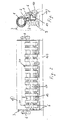
- a corrugator unit comprises at least two corrugator rolls 1 and 2, which are supported at their ends, rotatably about their axis, inside a framework 3.
- the rolls are rotatably driven, so as to be counterrotating.
- the roll 1, having a considerably greater diameter than the roll 2, according to a predetermined ratio of 1/2 to 1/10, is supported so as to be stationary with respect to transverse translations of its axis of rotation, particularly in the direction of the line passing through the axes of rotation of the two rolls 1 and 2.
- the second roll 2 is rotatably supported by end hubs 102, at the end of swinging arms 4, swingably pivoted on axes 5, projecting parallel to the axes of the rolls 1, 2, out of the framework 3.
- Figures 7 and 8 show the differences between a corrugator unit whose rolls have substantially identical diameters and a corrugator unit according to the present invention.
- the peripheral teeth or corrugations 101, 202 form a much longer labyrinth than the one formed by two corrugator rolls 1, 2, as usable according to the principle of the present invention. Due to the shorter radius of the roll 2, a smaller number of teeth or corrugations 101, 202 are in partial engagement. Therefore, the labyrinth in which the paper C is gripped is much shorter, thereby greatly reducing the risk of its being broken during the corrugation process, and involving less critical operational settings of the corrugator unit.
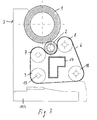
- the roll 2 with the smaller diameter rests on a cradle 106, which is formed by a set of adjacent endless belts 6 driven around pulleys 7, 8, 9, 10. All the belts 6 are driven in such a way as to follow coincident paths in the axial direction of the roll, the driving pulleys 7, 8, 9, 10 being identical for each belt and axially coincident.
- the pulleys 7, 8, 9, 10 are arranged so that the lines joining their axes of rotation form a trapezoid, whereas the driving pulleys 7, 8, which are level with the roll 2 have their axes aligned on a plane substantially parallel to the tangent passing trough the contact line between the two corrugator rolls 1, 2, which plane containing said axes is slightly staggered with respect to the axis of rotation of the roll 2, on the side opposite to the roll 1.
- the two pulleys 7, 8 which are level with the corrugator roll 2 have a diameter of the same order as the diameter of the latter, whereas their distance from the latter substantially corresponds to the thickness of the belt 6.
- All the pulleys 7 to 10 associated to each belt 6 are supported at the ends of arms 11, 12, 13, overhangingly projecting out of a central beam 14, extending parallel to the axes of the rolls 1, 2.
- the beam 14 is particularly swingably supported by a shaft 15, which is also the axis of rotation of the lower pulley 9, placed under the roll 1, whereas, on the opposite, outer side, the beam 14 is supported by the base 103, by means of linear actuators 16, such as hydraulic cylinders or similar, which allow to swing the whole beam 14 between two extreme operating and rest positions.
- linear actuators 16 such as hydraulic cylinders or similar, which allow to swing the whole beam 14 between two extreme operating and rest positions.
- the belts 6 In the operating position, shown in the figures, the belts 6 bring the roll 2 into contact with the roll 1, with the peripheral teeth and corrugations of the two rolls 1, 2 being in mutual engagement.
- the belts 6, i.e. the cradle 106 displaces the roll 2 from the roll 1, to allow for the introduction of the sheet of paper, or other similar material to be corrugated therebetween.
- the actuators 16 are disposed in a predetermined arrangement over the length of the roll 2 and of the beam 14, and are articulated on one side to the base 103, and on the other side to a corresponding arm 17 of the beam 14.
- At least one pulley 10 of each belt 6 is supported at the end of an arm 13, which is supported by the beam 14 so as to swing 110 about an axis parallel to that of the associated pulley 10, a linear actuator 18 being interposed between the arm 13 and a stationary matching member of the beam 14.
- the belts 6 are arranged in a predetermined order over the axial length of the roll 2 and particularly, in order to reduce the number of actuators, the belts 6 are supported in groups each formed by a pair of belts, said groups of belts, indicated as 20, being uniformly arranged, i.e. equally spaced all along the roll 2. Particularly, the axial distance between the belts of one group is shorter than the axial distance between the individual groups.
- Suitable means, well known per se, for controlling the actuators 18 allow to apply such a tension on the belts, as to obtain a uniform pushing force over the whole axial length of the roll 2 against the roll 1.
- each group or alternatively each belt 6 is provided with a separate actuator 18, the tension of the belts 6, associated to different segments of the roll 2 may be varied locally, thus allowing for a compensation of any local unevenness, and always ensuring a uniform pressure of the roll 2 against the roll 1, over their whole length.
- a swinging beam 14 allows to displace the roll 2 from the roll 1, so as to be able to introduce the paper, and to clean the machine.
- the actuators 16 are also arranged all along the roll 2 and the beam 14, preferably being associated to the intermediate areas between the individual groups 20 of belts 6.
- One of the rolls 1, 2 or both are rotatably driven, whereas the belts 6 may be idle or also rotatably driven about the pulleys 7 to 10, so as to be synchronized with the speed of rotation of the roll 2.
Landscapes
- Engineering & Computer Science (AREA)
- Mechanical Engineering (AREA)
- Machines For Manufacturing Corrugated Board In Mechanical Paper-Making Processes (AREA)
- Paper (AREA)
- Laminated Bodies (AREA)
Claims (8)
- Welleinrichtung, insbesondere für Blätter oder Bahnen aus Papier oder dergleichen, mit wenigstens zwei Walzen (1, 2), die eine gezahnte oder gewellte Oberfläche (101, 202) haben und gegenseitig in Eingriff sind,
wobei die Walzen (1, 2) um ihre Achsen an ihren Enden drehbar unterstützt sind und in radialer Richtung gegeneinander durch einen vorgegebenen Druck oder eine Kraft gedrückt sind, welche über die gesamte axiale Länge der Walzen wirkt, und
wobei wenigstens eine Walze (2) gegen die andere Walze (1) bewegbar ist und durch einen Träger (106) gehalten wird, welcher gegen die Seite der bewegbaren Walze (2) diametral gegenüber der anderen Walze (1) mit einer Vielzahl von Kontaktstellen oder-bereichen anliegt, welche über die axiale Länge verteilt sind,
dadurch gekennzeichnet, daß der Träger (106) aus einem Satz von endlos rotierenden Stützriemen (6), (7, 8, 9, 10) besteht, welche entlang der Länge der bewegbaren Walze (2) angeordnet sind,
wobei Mittel vorgesehen sind, um die Riemen (6) mit einer vorbestimmten Kraft gegen die zugehörig bewegte Walze (2) zu drücken. - Welleinrichtung nach Anspruch 1,
dadurch gekennzeichnet, daß der Träger (106) und die durch den Träger gehaltene bewegbare Walze (2) derart unterstützt sind, daß sie von einer Betriebsposition, in welcher die von dem Träger gehaltene Walze (2) tangential zu der anderen Walze (1) ist und gegen diese gedrückt ist, in eine Ruheposition, in welcher die von dem Träger gehaltene Walze (2) über einen vorbestimmten Bereich von der anderen Walze (1) entfernt ist, bewegbar (4, 5, 15, 16, 17) sind. - Welleinrichtung nach Anspruch 1 oder 2,
dadurch gekennzeichnet, daß wenigstens eine und/oder beide Walzen (1, 2) und/oder die Riemen (6), welche den Träger (106) bilden, drehbar angetrieben sind. - Welleinrichtung nach einem der vorhergehenden Ansprüche,
dadurch gekennzeichnet, daß die Riemen (6) über Riemenscheiben (7, 8, 9, 10) angetrieben sind, welche alle von einem gemeinsamen Rahmen (14) gestützt sind, wobei der Rahmen (14) bewegbar von und zu der anderen Walze (1) zwischen der Ruheposition und der Betriebsposition ist. - Welleinrichtung nach einem oder mehreren der vorhergehenden Ansprüche,
dadurch gekennzeichnet, daß für jeden einzelnen Riemen oder für Gruppen davon Riemenspannmittel (10, 13, 18, 19) vorgesehen sind. - Welleinrichtung nach einem oder mehreren der vorhergehenden Ansprüche,
dadurch gekennzeichnet, daß jeder Riemen (6) um vier Riemenscheiben (7, 8, 9, 10) angetrieben ist, welche die Ecken eines Trapezoids bilden und durch Arme (11, 12, 13) unterstützt sind, welche sich von einem gemeinsamen zentralen Balken (14) aus verzweigen, der sich über die Länge der von dem Träger gehaltenen Walze (2) erstreckt, wobei der Träger (106) durch den Riemenzweig im Bereich dieser Walze (2) gebildet ist, und die Riemenscheiben (7, 8), welche dem Riemenzweig gegenüberliegen, sind mit ihren Achsen parallel zu der Achse der Walze (2) auf der Seite diametral gegenüber der anderen Walze (1). - Welleinrichtung nach Anspruch 6,
dadurch gekennzeichnet, daß die Ebene, in welcher die Achsen der Riemenscheiben (7, 8) liegen, welche den Riemenzweigen gegenüberliegen und den Träger (106) bilden, parallel zu der Ebene tangential zu den Walzen (1, 2) ist und die Tangente dazwischen durchläuft. - Welleinrichtung nach einem oder mehreren der vorhergehenden Ansprüche,
dadurch gekennzeichnet, daß eine Walze (1) einen größeren Durchmesser hat und derart unterstützt wird, daß sie stationär bezüglich einer Bewegung quer zu ihrer Rotationsachse ist, wobei die andere Walze (2) einen kleineren Durchmesser hat und rotierbar durch den Träger (106) gehalten wird und innerhalb von Grenzen quer zu ihrer Achse bewegbar ist.
Applications Claiming Priority (2)
| Application Number | Priority Date | Filing Date | Title |
|---|---|---|---|
| IT97SV000036A IT1298011B1 (it) | 1997-07-11 | 1997-07-11 | Gruppo ondulare, in particolare per fogli o nastri di materiale cartaceo, o simili. |
| ITSV970036 | 1997-07-11 |
Publications (2)
| Publication Number | Publication Date |
|---|---|
| EP0890429A1 EP0890429A1 (de) | 1999-01-13 |
| EP0890429B1 true EP0890429B1 (de) | 2003-10-08 |
Family
ID=11408232
Family Applications (1)
| Application Number | Title | Priority Date | Filing Date |
|---|---|---|---|
| EP98112227A Expired - Lifetime EP0890429B1 (de) | 1997-07-11 | 1998-07-02 | Welleinrichtung, insbesondere für Blätter oder Bahnen aus Papier oder dergleichen |
Country Status (6)
| Country | Link |
|---|---|
| US (2) | US6478066B1 (de) |
| EP (1) | EP0890429B1 (de) |
| AT (1) | ATE251545T1 (de) |
| DE (1) | DE69818754T2 (de) |
| ES (1) | ES2205334T3 (de) |
| IT (1) | IT1298011B1 (de) |
Families Citing this family (10)
| Publication number | Priority date | Publication date | Assignee | Title |
|---|---|---|---|---|
| US6012501A (en) * | 1996-03-26 | 2000-01-11 | Marquip, Inc. | Single facer with small intermediate corrugating roll and variable wrap arm device |
| IT1298011B1 (it) * | 1997-07-11 | 1999-12-20 | Agnati Spa | Gruppo ondulare, in particolare per fogli o nastri di materiale cartaceo, o simili. |
| WO2000046020A1 (en) * | 1999-02-04 | 2000-08-10 | Marquip, Inc. | Single facer with small diameter high wear corrugating roll |
| FI108468B (fi) * | 1999-03-15 | 2002-01-31 | Maping Ky L Huotari | Menetelmõ ja laite paperin, kartongin tai sen kaltaisen kõsittelemiseen |
| IT1309926B1 (it) * | 1999-11-05 | 2002-02-05 | Agnati Spa | Cilindro ondulatore smorzante. |
| US6644653B1 (en) | 2000-11-02 | 2003-11-11 | Agnati S.P.A. | Damping corrugator roll |
| US6733408B2 (en) * | 2002-04-04 | 2004-05-11 | Martin Yale Industries, Inc. | Belt tension/drive for pinch roller system |
| BE1015327A3 (nl) * | 2003-01-27 | 2005-01-11 | Corrutech Nv | Werkwijze en inrichting voor het vervaardigen van golfkarton of dergelijke. |
| JP4418466B2 (ja) * | 2005-02-25 | 2010-02-17 | 三菱重工業株式会社 | 片面段ボール製造装置 |
| ES2686072T3 (es) * | 2013-04-19 | 2018-10-16 | Bp Agnati S.R.L. | Un dispositivo de corrugación para hojas de material de papel |
Family Cites Families (28)
| Publication number | Priority date | Publication date | Assignee | Title |
|---|---|---|---|---|
| US1186998A (en) * | 1915-09-02 | 1916-06-13 | Samuel M Langston | Machine for making corrugated paper. |
| US1519280A (en) * | 1922-01-14 | 1924-12-16 | Wandel Kurt | Method and apparatus for the manufacture of corrugated board |
| US1642782A (en) * | 1923-03-20 | 1927-09-20 | Samuel M Langston | Machine for making corrugated paper |
| US3192560A (en) * | 1963-11-08 | 1965-07-06 | Du Pont | Apparatus for heat treating porous sheet material |
| US3382133A (en) * | 1965-02-26 | 1968-05-07 | Little Inc A | Means for corrugating webs transversely |
| US3413915A (en) * | 1965-06-10 | 1968-12-03 | Du Pont | Magnetically biased pressure application to running length materials |
| US3390040A (en) * | 1965-08-17 | 1968-06-25 | Langston Company | Single facer machine |
| DE1511062B1 (de) * | 1966-08-18 | 1970-09-03 | Peters Maschf Werner H K | Wellpappenmaschine |
| US3527638A (en) * | 1967-09-20 | 1970-09-08 | Mas Fab Werner H K Peters Gmbh | Corrugated paper board machine with means for forming a crown on a corrugating roll |
| US3556000A (en) * | 1967-12-08 | 1971-01-19 | Du Pont | Magnetic calender |
| US3973894A (en) | 1970-11-02 | 1976-08-10 | Continental Gummi-Werke Aktiengesellschaft | Device for the production of toothed belts |
| CH577381A5 (de) * | 1974-04-25 | 1976-07-15 | Escher Wyss Ag | |
| US4046612A (en) | 1975-03-05 | 1977-09-06 | Gte Sylvania Incorporated | Method for producing a bilayered green ceramic tape |
| FI52394C (fi) * | 1975-12-31 | 1977-08-10 | Valmet Oy | Taipumakompensoitu, päistään kuormitettu tela, etenkin paperikoneen pu ristintela. |
| DE8331822U1 (de) * | 1983-11-07 | 1984-02-09 | Werner H.K. Peters Maschinenfabrik Gmbh, 2000 Hamburg | Einseitige wellpappenmaschine |
| US4531996A (en) | 1984-05-09 | 1985-07-30 | Corrugating Roll Corporation | Single facer corrugating machine |
| US4874457A (en) | 1988-04-21 | 1989-10-17 | Mcneil-Pc, Inc. | Web corrugating apparatus |
| DE8915517U1 (de) * | 1989-02-08 | 1990-08-30 | Peters Maschinenfabrik Gmbh, 2000 Hamburg | Einseitige Wellpappenmaschine |
| US5392702A (en) * | 1989-02-15 | 1995-02-28 | Bellmatic, Ltd. | Magnetic rolling system having rollers with laminated ply units disposed therein |
| DE4006003A1 (de) * | 1989-09-15 | 1991-03-28 | Kuesters Eduard Maschf | Wellpappenmaschine |
| JP2592183B2 (ja) * | 1990-12-25 | 1997-03-19 | 三菱重工業株式会社 | 片面段ボール製造機 |
| DE4420958A1 (de) * | 1994-06-16 | 1995-12-21 | Bhs Corr Masch & Anlagenbau | Maschine zur Herstellung einer einseitig kaschierten Wellpappebahn |
| DE4420726A1 (de) * | 1994-06-16 | 1995-12-21 | Bhs Corr Masch & Anlagenbau | Maschine zur Herstellung einer mindestens einseitig kaschierten Wellpappebahn |
| US5628865A (en) * | 1996-03-26 | 1997-05-13 | Marquip, Inc. | Single facer with small intermediate corrugating roll |
| US6012501A (en) * | 1996-03-26 | 2000-01-11 | Marquip, Inc. | Single facer with small intermediate corrugating roll and variable wrap arm device |
| US5951816A (en) | 1996-03-26 | 1999-09-14 | Marquip, Inc. | Single facer with small intermediate corrugating roll |
| IT1298011B1 (it) * | 1997-07-11 | 1999-12-20 | Agnati Spa | Gruppo ondulare, in particolare per fogli o nastri di materiale cartaceo, o simili. |
| US6644653B1 (en) * | 2000-11-02 | 2003-11-11 | Agnati S.P.A. | Damping corrugator roll |
-
1997
- 1997-07-11 IT IT97SV000036A patent/IT1298011B1/it active IP Right Grant
-
1998
- 1998-07-02 EP EP98112227A patent/EP0890429B1/de not_active Expired - Lifetime
- 1998-07-02 ES ES98112227T patent/ES2205334T3/es not_active Expired - Lifetime
- 1998-07-02 AT AT98112227T patent/ATE251545T1/de not_active IP Right Cessation
- 1998-07-02 DE DE69818754T patent/DE69818754T2/de not_active Expired - Fee Related
- 1998-07-10 US US09/113,506 patent/US6478066B1/en not_active Expired - Fee Related
-
2002
- 2002-11-01 US US10/285,414 patent/US20030054136A1/en not_active Abandoned
Also Published As
| Publication number | Publication date |
|---|---|
| ITSV970036A1 (it) | 1999-01-11 |
| DE69818754T2 (de) | 2004-08-19 |
| ITSV970036A0 (it) | 1997-07-11 |
| IT1298011B1 (it) | 1999-12-20 |
| DE69818754D1 (de) | 2003-11-13 |
| ATE251545T1 (de) | 2003-10-15 |
| ES2205334T3 (es) | 2004-05-01 |
| EP0890429A1 (de) | 1999-01-13 |
| US20030054136A1 (en) | 2003-03-20 |
| US6478066B1 (en) | 2002-11-12 |
Similar Documents
| Publication | Publication Date | Title |
|---|---|---|
| EP0890429B1 (de) | Welleinrichtung, insbesondere für Blätter oder Bahnen aus Papier oder dergleichen | |
| US6863107B2 (en) | Device for applying a spot embossing pattern to a web of multi-ply tissue paper | |
| US5732902A (en) | Method and device in winding of a web | |
| US3973483A (en) | Apparatus for the continuous pressure treatment of a web | |
| GB2157660A (en) | Revolving transfer roll | |
| CN1203549A (zh) | 两个压花辊筒转速不同的压花和层压机 | |
| US20080073033A1 (en) | Machine for producing a corrugated cardboard web lined at least on one side | |
| US4932855A (en) | Press for the continuous production of chip-boards and fiber boards | |
| EP1024314A1 (de) | Vorrichtung zum Spannen von um Rollen gewickelten flexiblelen Elementen | |
| SE421199B (sv) | Maskin for vikning av arkmaterial | |
| WO2003031170A1 (en) | Device and method for applying a spot embossing pattern to a web of multi-ply tissue paper | |
| JP3737785B2 (ja) | 連続紙の幅調整装置 | |
| KR19980086964A (ko) | 소형 중간 주름 형성 롤을 갖는 개량된 편면 페이서 | |
| KR19990078044A (ko) | 작은중간파형성형롤및가변형랩아암장치를갖는단일페이서 | |
| GB2188074A (en) | Single facer machine | |
| US5680979A (en) | Drawing roller drive | |
| EP0607283B1 (de) | Walze mit mitteln zum axialen bewegen derselben | |
| CN115679742B (zh) | 一种造纸设备的压榨装置 | |
| US4464986A (en) | Device for reducing the vibration of a press section constituted by two or more rolls pressed one against the other in a paper manufacturing machine | |
| EP1021606B1 (de) | Rauhmaschine mit einer vorrichtung zur verstellung des laufes der zu behandelden textilen warenbahn | |
| JP2678826B2 (ja) | ウェブの巻取り装置 | |
| US6602375B2 (en) | Single facer drive apparatus | |
| CN219903053U (zh) | 一种用于卷材生产的定厚辊结构、定厚装置及生产设备 | |
| KR101714993B1 (ko) | 무한 벨트 교체 장치 및 방법 | |
| RU2167351C1 (ru) | Устройство передачи движения (варианты) |
Legal Events
| Date | Code | Title | Description |
|---|---|---|---|
| PUAI | Public reference made under article 153(3) epc to a published international application that has entered the european phase |
Free format text: ORIGINAL CODE: 0009012 |
|
| AK | Designated contracting states |
Kind code of ref document: A1 Designated state(s): AT BE CH DE DK ES FI FR GB GR IE IT LI LU MC NL PT SE |
|
| AX | Request for extension of the european patent |
Free format text: AL;LT;LV;MK;RO;SI |
|
| 17P | Request for examination filed |
Effective date: 19990611 |
|
| AKX | Designation fees paid |
Free format text: DE ES FR GB |
|
| RBV | Designated contracting states (corrected) |
Designated state(s): AT BE CH DE DK ES FI FR GB GR IE IT LI LU MC NL PT SE |
|
| 17Q | First examination report despatched |
Effective date: 20020823 |
|
| GRAH | Despatch of communication of intention to grant a patent |
Free format text: ORIGINAL CODE: EPIDOS IGRA |
|
| GRAS | Grant fee paid |
Free format text: ORIGINAL CODE: EPIDOSNIGR3 |
|
| GRAA | (expected) grant |
Free format text: ORIGINAL CODE: 0009210 |
|
| AK | Designated contracting states |
Kind code of ref document: B1 Designated state(s): AT BE CH DE DK ES FI FR GB GR IE IT LI LU MC NL PT SE |
|
| PG25 | Lapsed in a contracting state [announced via postgrant information from national office to epo] |
Ref country code: NL Free format text: LAPSE BECAUSE OF FAILURE TO SUBMIT A TRANSLATION OF THE DESCRIPTION OR TO PAY THE FEE WITHIN THE PRESCRIBED TIME-LIMIT Effective date: 20031008 Ref country code: FI Free format text: LAPSE BECAUSE OF FAILURE TO SUBMIT A TRANSLATION OF THE DESCRIPTION OR TO PAY THE FEE WITHIN THE PRESCRIBED TIME-LIMIT Effective date: 20031008 Ref country code: BE Free format text: LAPSE BECAUSE OF FAILURE TO SUBMIT A TRANSLATION OF THE DESCRIPTION OR TO PAY THE FEE WITHIN THE PRESCRIBED TIME-LIMIT Effective date: 20031008 Ref country code: AT Free format text: LAPSE BECAUSE OF FAILURE TO SUBMIT A TRANSLATION OF THE DESCRIPTION OR TO PAY THE FEE WITHIN THE PRESCRIBED TIME-LIMIT Effective date: 20031008 |
|
| REG | Reference to a national code |
Ref country code: GB Ref legal event code: FG4D |
|
| REG | Reference to a national code |
Ref country code: CH Ref legal event code: EP |
|
| REG | Reference to a national code |
Ref country code: IE Ref legal event code: FG4D |
|
| REF | Corresponds to: |
Ref document number: 69818754 Country of ref document: DE Date of ref document: 20031113 Kind code of ref document: P |
|
| PG25 | Lapsed in a contracting state [announced via postgrant information from national office to epo] |
Ref country code: SE Free format text: LAPSE BECAUSE OF FAILURE TO SUBMIT A TRANSLATION OF THE DESCRIPTION OR TO PAY THE FEE WITHIN THE PRESCRIBED TIME-LIMIT Effective date: 20040108 Ref country code: GR Free format text: LAPSE BECAUSE OF FAILURE TO SUBMIT A TRANSLATION OF THE DESCRIPTION OR TO PAY THE FEE WITHIN THE PRESCRIBED TIME-LIMIT Effective date: 20040108 Ref country code: DK Free format text: LAPSE BECAUSE OF FAILURE TO SUBMIT A TRANSLATION OF THE DESCRIPTION OR TO PAY THE FEE WITHIN THE PRESCRIBED TIME-LIMIT Effective date: 20040108 |
|
| REG | Reference to a national code |
Ref country code: CH Ref legal event code: AEN Free format text: DAS PATENT IST AUF GRUND DES WEITERBEHANDLUNGSANTRAGS VOM 04.02.2004 REAKTIVIERT WORDEN. |
|
| NLV1 | Nl: lapsed or annulled due to failure to fulfill the requirements of art. 29p and 29m of the patents act | ||
| REG | Reference to a national code |
Ref country code: ES Ref legal event code: FG2A Ref document number: 2205334 Country of ref document: ES Kind code of ref document: T3 |
|
| PG25 | Lapsed in a contracting state [announced via postgrant information from national office to epo] |
Ref country code: LU Free format text: LAPSE BECAUSE OF NON-PAYMENT OF DUE FEES Effective date: 20040702 Ref country code: IE Free format text: LAPSE BECAUSE OF NON-PAYMENT OF DUE FEES Effective date: 20040702 |
|
| ET | Fr: translation filed | ||
| PG25 | Lapsed in a contracting state [announced via postgrant information from national office to epo] |
Ref country code: MC Free format text: LAPSE BECAUSE OF NON-PAYMENT OF DUE FEES Effective date: 20040731 |
|
| PLBE | No opposition filed within time limit |
Free format text: ORIGINAL CODE: 0009261 |
|
| STAA | Information on the status of an ep patent application or granted ep patent |
Free format text: STATUS: NO OPPOSITION FILED WITHIN TIME LIMIT |
|
| 26N | No opposition filed |
Effective date: 20040709 |
|
| REG | Reference to a national code |
Ref country code: IE Ref legal event code: MM4A |
|
| PG25 | Lapsed in a contracting state [announced via postgrant information from national office to epo] |
Ref country code: IT Free format text: LAPSE BECAUSE OF NON-PAYMENT OF DUE FEES;WARNING: LAPSES OF ITALIAN PATENTS WITH EFFECTIVE DATE BEFORE 2007 MAY HAVE OCCURRED AT ANY TIME BEFORE 2007. THE CORRECT EFFECTIVE DATE MAY BE DIFFERENT FROM THE ONE RECORDED. Effective date: 20050702 |
|
| PGFP | Annual fee paid to national office [announced via postgrant information from national office to epo] |
Ref country code: GB Payment date: 20060718 Year of fee payment: 9 |
|
| PGFP | Annual fee paid to national office [announced via postgrant information from national office to epo] |
Ref country code: CH Payment date: 20060719 Year of fee payment: 9 |
|
| PGFP | Annual fee paid to national office [announced via postgrant information from national office to epo] |
Ref country code: FR Payment date: 20060720 Year of fee payment: 9 |
|
| PGFP | Annual fee paid to national office [announced via postgrant information from national office to epo] |
Ref country code: DE Payment date: 20060722 Year of fee payment: 9 |
|
| PGFP | Annual fee paid to national office [announced via postgrant information from national office to epo] |
Ref country code: ES Payment date: 20060830 Year of fee payment: 9 |
|
| PG25 | Lapsed in a contracting state [announced via postgrant information from national office to epo] |
Ref country code: PT Free format text: LAPSE BECAUSE OF NON-PAYMENT OF DUE FEES Effective date: 20040308 |
|
| REG | Reference to a national code |
Ref country code: CH Ref legal event code: PL |
|
| GBPC | Gb: european patent ceased through non-payment of renewal fee |
Effective date: 20070702 |
|
| PG25 | Lapsed in a contracting state [announced via postgrant information from national office to epo] |
Ref country code: LI Free format text: LAPSE BECAUSE OF NON-PAYMENT OF DUE FEES Effective date: 20070731 Ref country code: DE Free format text: LAPSE BECAUSE OF NON-PAYMENT OF DUE FEES Effective date: 20080201 Ref country code: CH Free format text: LAPSE BECAUSE OF NON-PAYMENT OF DUE FEES Effective date: 20070731 |
|
| PG25 | Lapsed in a contracting state [announced via postgrant information from national office to epo] |
Ref country code: GB Free format text: LAPSE BECAUSE OF NON-PAYMENT OF DUE FEES Effective date: 20070702 |
|
| REG | Reference to a national code |
Ref country code: FR Ref legal event code: ST Effective date: 20080331 |
|
| PG25 | Lapsed in a contracting state [announced via postgrant information from national office to epo] |
Ref country code: FR Free format text: LAPSE BECAUSE OF NON-PAYMENT OF DUE FEES Effective date: 20070731 |
|
| REG | Reference to a national code |
Ref country code: ES Ref legal event code: FD2A Effective date: 20070703 |
|
| PG25 | Lapsed in a contracting state [announced via postgrant information from national office to epo] |
Ref country code: ES Free format text: LAPSE BECAUSE OF NON-PAYMENT OF DUE FEES Effective date: 20070703 |