EP0890435A1 - Vorrichtung zum Befestigen einer biegsamen Platte auf dem Umfang des Zylinders einer Lackiermaschine - Google Patents
Vorrichtung zum Befestigen einer biegsamen Platte auf dem Umfang des Zylinders einer Lackiermaschine Download PDFInfo
- Publication number
- EP0890435A1 EP0890435A1 EP98112367A EP98112367A EP0890435A1 EP 0890435 A1 EP0890435 A1 EP 0890435A1 EP 98112367 A EP98112367 A EP 98112367A EP 98112367 A EP98112367 A EP 98112367A EP 0890435 A1 EP0890435 A1 EP 0890435A1
- Authority
- EP
- European Patent Office
- Prior art keywords
- plate
- edge
- cylinder
- hanging bar
- strip
- Prior art date
- Legal status (The legal status is an assumption and is not a legal conclusion. Google has not performed a legal analysis and makes no representation as to the accuracy of the status listed.)
- Granted
Links
Images

Classifications
-
- B—PERFORMING OPERATIONS; TRANSPORTING
- B41—PRINTING; LINING MACHINES; TYPEWRITERS; STAMPS
- B41F—PRINTING MACHINES OR PRESSES
- B41F27/00—Devices for attaching printing elements or formes to supports
- B41F27/12—Devices for attaching printing elements or formes to supports for attaching flexible printing formes
- B41F27/1218—Devices for attaching printing elements or formes to supports for attaching flexible printing formes comprising printing plate tensioning devices
- B41F27/1225—Devices for attaching printing elements or formes to supports for attaching flexible printing formes comprising printing plate tensioning devices moving in the printing plate end substantially rectilinearly
- B41F27/1243—Devices for attaching printing elements or formes to supports for attaching flexible printing formes comprising printing plate tensioning devices moving in the printing plate end substantially rectilinearly by pivotal or swivelling motion, e.g. by means of a rocking lever
Definitions
- the invention relates to an axially extending Clamping channel of a cylinder arranged device to attach a flexible plate the circumference of the cylinder, especially for fastening a varnish or printing plate or a rubber blanket on the circumference of a lacquer or blanket cylinder a painting machine, at the beginning and formed at the end of the plate, in the Edges pointing to the tensioning channel, with an initial edge fastening device the start edge the plate and with an end edge fastening device held the end edge of the plate is.
- the invention is therefore based on the object a device of the type mentioned create that with a simple design very little Requires space so that the start and end edge of the The plate is very close together. This has to Consequence that almost the full circumferential length of the painting cylinder available as usable painting length stands. The usable rolling of the coating cylinder circumference is therefore very large, that is, it exists optimal format use.
- this object is achieved by that the leading edge fastener of an initial hanging bar is formed by the starting edge of the plate is gripped behind that the end edge fastener of one of a clamping shaft cantilevered end hanging bar which is gripped by the end edge of the plate and that the start and end edge respectively without the use of clamping devices, but only by engaging in the Start and end rails are held.
- the invention thus provides that for attachment the plate on the cylinder only the initial and End edge by means of the start hanging bar respectively of the end hanging bar become.
- Start and end mounting rails can be therefore facing each other with only a very short distance, the distance must only be so large that on the one hand by moving relative to each other of the two strips stretch the plate the size of the cylinder is possible, that is, it a sufficient span must be possible, and on the other hand the start and / or end edge of the Plate a sufficiently large entry gap for Are available to the backhand to the respective To enable fastening device during assembly or solve during disassembly can.
- the end hanging rail in protrudes tangentially from the tension shaft.
- the end suspension strips diverged - in cross section seen- to this radial with the the trailing edge area behind the panel of the end suspension rail around the intersection of the radial lies with the circumference of the cylinder.
- the initial hanging strip receiving the starting edge diverges (also seen in cross section), that is, the two ledges are inclined towards each other and only form between themselves the narrowest possible gap, which is about Height of an imaginary on the outer circumference of the cylinder along the line.
- the end hanging strip is preferably elastic in itself, namely designed as a spring element.
- the elastic property can cause inaccuracies at the ends of the plate, for example, by Manufacturing tolerances (parallelism inaccuracies) are caused to be balanced.
- the end hook arranged on the already mentioned tension shaft it can be turned by turning the Tensioning shaft - in the direction of the initial hanging bar move, creating the plate on the circumference of the cylinder is excited.
- the tension shaft a spring element, preferably in the form of a Torsion bar, assigned, which makes the plate is always under tension, which means possible Rolling effects and so on added become.
- the end suspension bar can act as a spring element be provided that the end hanging bar eccentric is stored, that means it can in the area one end be adjusted to make possible Compensate for parallelism inaccuracies of the plate.
- the eccentric camp is - as already mentioned - in an end area of the end suspension rail, while the other end area accordingly is pivotally mounted. Since also at the beginning of the record Parallelism inaccuracies and the like can occur is preferably provided that the initial hanging bar also the parallelism inaccuracies can be adjusted by a "moveable" start mounting bracket attachment is present.
- the one end area of the start hanging bar by means of a fastening element for example a threaded screw is such that a pivoting possibility of Initial hanging bar is created and that in the other End area of the start hanging bar one Adjustment option, in particular by means of a lever mechanism exists, so that a corresponding It is possible to incline the initial mounting rail becomes.
- the grip angle of the start and / or end edge is less than 90 °, preferably about 60 °, that is, there is virtually a positive connection to the respective Hanging bar in front. A slight one The tension of the plate closes in this way and Way out that one end of the plate can come loose. On the other hand can the ends of the plate without effort lifted when releasing the circumferential tension become, that is, a plate change is extraordinary easy and effortless.
- the initial hanging bar and / or the end hanging rail in the cover on the start edge and / or the end edge formation the plate in their respective rear grip area have such cross-sectional contours, that a form-fitting, large area lies on top of each other the parts is achieved. This offers optimal safety and reproducibility.
- start edge and / or the end edge by bent Areas of the plate formed.
- the bent Area allow the grip behind the initial hanging bar or end hanging rails, so that additional, serving the attachment Parts are not required.
- start edge and / or the end edge by at the beginning of the board and / or on Panel end attached profile end strips formed are.
- the profile end strips allow a precise fit Interact with the respective bar and have high dimensional stability.
- each profile end strip preferably has a clamping channel into which the plate engages for attachment.
- the profile end strip on the plate Gluing is held.
- too Profilendance have a channel in which the Plate end or the beginning of the plate below Interposition of an adhesive intervenes.
- the plate can have a plastic carrier material, in particular polyester or consist of this material.
- the plate is technical similar to a rubber blanket, but can for example used as a lacquer plate for painting become.
- the lateral position of the plate on the Cylinder, for example the center position Alignment means that it fits perfectly and is reproducible given.
- the alignment device is preferably from at least one pin on the initial hanging bar and / or the end hanging bar and a stop edge interacting with this pin of the plate.
- the stop edge can preferably by means of a recess in the plate be formed, the recess in particular in the area of the start edge and / or end edge the plate.
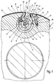
- Figure 1 shows a portion of a cylinder 1, which is designed as a painting cylinder 2 and in used a painting machine, not shown becomes.
- the cylinder 1 is - parallel to its axis of rotation - penetrated by a clamping channel 3 which opens into the outer surface 4 of the painting cylinder 2.
- the tensioning channel 3 a part-circular wall contour 5, whose Circle center 6 on a radial 7 of the painting cylinder 2 lies.
- the part-circular wall contour 5 goes into one Step contour 8 over a base 9 and has a side surface 10, base and The side surface is preferably at right angles to each other.
- A is rotatably supported within the tensioning channel 3 hollow tension shaft 13, -in the area of its lateral surface 14- has a flat 15 on which one End edge fastening device 16 is arranged, which has an end hanging bar 17.
- the end hanging strip extends 17 projecting from the tension shaft 13 away, with the free end 18 of the end hanging bar 17 approximately up to the imaginary lateral surface 4 within of the tension channel 3 extends.
- the attachment the end hanging bar 17 on the tension shaft 13 takes place by means of threaded screws 19, several of which spaced apart over the length of the arrangement are arranged to each other, each threaded screw 19 a receiving bore of the end hanging bar 17 interspersed and in a threaded hole the hollow tension shaft 13 is screwed.
- a spring element is located within the tension shaft 13 20, which is designed as a torsion bar 21 is. This makes it possible for the rotatably mounted Preload tensioning shaft 13 in the direction of rotation.
- an initial edge fastening device 22 used which is an initial hanging bar 23 has.
- the start hanging bar 23 is in one end region with a Threaded screw 24 connected to the painting cylinder 2.
- a stepped bore 25 on the threaded screw 24 is penetrated, the threaded portion the threaded screw 24 in a corresponding Threaded bore 26 of the painting cylinder 2 is screwed in.
- the initial hanging bar 23 has an adjustment device, especially a lever-like one Adjustment device so that it is in the circumferential direction of the painting cylinder 2 considered Axis of rotation of the painting cylinder inclined can be to any parallelism inaccuracies one on the outer surface 4 of the painting cylinder Compensate 2 flexible plate 28 to be fastened to be able to.
- a corresponding possibility is given at the end hanging bar 17. This is created in that one end of the end hook 17 is mounted eccentrically, so that possible parallelism inaccuracies of the plate 28 can be compensated.
- the plate 28 is a lacquer plate 29 trained so that painting work with her can be carried out.
- the plate 28 instructs an edge 31 at its beginning 30 and 32 at its end an edge 33, the edge 31 being a starting edge 34 and the edge 33 forms an end edge 35.
- Start edge 34 and end edge 35 are by bending of the respective end regions of the plate 28. The turn is made so that the start edge 34 and the end edge 35 each adapted an acute angle to the lateral surface 4 Form the contour of the plate 28.
- This hook-shaped Contours become backhand angles from preferably formed about 60 °.
- the rear grip angles corresponding counter contours are on the initial hanging bar 23 and in the area of Free end 18 of the end hanging bar 17 is formed.
- the arrangement is such that the Start hanging bar 23 and the end hanging bar 17 in their respective rear grip area Cross-sectional contours have a shape-matched large contact of the start edge 34 and the end edge 35 of the plate 28 is present. That at the start edge 34 and the end edge 35 adjacent areas of the plate 28, which on the imaginary lateral surface contour of the painting cylinder 2 or approximately the outer surface contour follow, are also supported extensively on corresponding Areas of the initial hanging bar 23 as well as end hanging bar 17 from.
- the alignment device 42 Correct lateral alignment of plate 28 on cylinder 1, for example the middle position, is ensured by the alignment device 42.
- This has a pin 43 with a head 43 ' on the one with an end in the start hanging bar 23 is held and its other, free End in the clamping channel 3 points.
- the one from the initial hanging bar 23 protruding pin 43 protrudes with the bottom of his head 43 'the surface the initial hanging bar 23 about one Length corresponding to the thickness of the plate 28.
- Of the Pin 43 penetrates a recess 44 which in the Start edge 34 of the plate 28 is introduced and forms a stop edge 45. This is a reproducible, precise lateral positioning the plate 28 possible.
- the recess 44 will superfluous if the stop edge 45 of a Side edge of the plate 28 is formed, which in in this case for the lateral alignment of the plate 28 move up to contact with pin 43 becomes.
- the pin 43 or the alignment device 42 also on the End hanging bar 17 may be arranged. It can several alignment devices 42 are also provided be. For the sake of clarity it is only an alignment device 42 shown in Figure 1.
- the embodiment of Figure 2 largely corresponds the embodiment of Figure 1, so that below only for significant changes is received.
- the plate 28 has no bent start and end edges, but that at the end areas of the plate 28 profile end strips 37 are attached, the -im Cross-section seen - have a V-shaped contour, the one profile end strip 37 is a starting edge 38 and the other profile end strip 37 has an end edge 39, the start edge 38 or the end edge 39 one each Has leg of the aforementioned V-shaped contour and the other leg of the respective V-shaped Provide contour with a channel 40 or 41 in which the respective start or End portion of the plate 28 engages and there is held by clamping or gluing.
Landscapes
- Engineering & Computer Science (AREA)
- Mechanical Engineering (AREA)
- Supply, Installation And Extraction Of Printed Sheets Or Plates (AREA)
Abstract
Description
- Figur 1
- einen Querschnitt durch einen Lackierzylinder einer nicht dargestellten Lackiermaschine im Bereich einer Befestigungsvorrichtung und
- Figur 2
- eine der Figur 1 entsprechende Darstellung nach einem weiteren Ausführungsbeispiel.
Claims (17)
- In einem axial verlaufenden Spannkanal eines Zylinders angeordnete Vorrichtung zum Befestigen einer biegsamen Platte auf dem Umfang des Zylinders, insbesondere zum Befestigen einer Lack- oder Druckplatte oder eines Gummituchs auf dem Umfang eines Lack- oder Gummituchzylinders einer Lackiermaschine, mit am Anfang und am Ende der Platte ausgebildeten, in den Spannkanal weisenden Kanten, wobei mit einer Anfangskantenbefestigungseinrichtung die Anfangskante der Platte sowie mit einer Endkantenbefestigungseinrichtung die Endkante der Platte gehalten ist, dadurch gekennzeichnet, daß die Anfangskantenbefestigungseinrichtung (22) von einer Anfangseinhängeleiste (23) gebildet ist, die von der Anfangskante (34,38) der Platte (28) hintergriffen wird, daß die Endkantenbefestigungseinrichtung (16) von einer von einer Spannwelle (13) auskragenden Endeinhängeleiste (17) gebildet ist, die von der Endkante (35,39) der Platte (28) hintergriffen wird und daß die Anfangs- und Endkante (34,38,35,39) jeweils ohne Verwendung von Klemmbeaufschlagungsmitteln, sondern lediglich durch Hintergriff an der Anfangs- und Endeinhängeleiste (23,17) gehalten sind.
- Vorrichtung nach Anspruch 1, dadurch gekennzeichnet, daß die Endeinhängeleiste (17) in tangentialer Richtung von der Spannwelle (13) auskragt.
- Vorrichtung nach einem der vorhergehenden Ansprüche, dadurch gekennzeichnet, daß die Endeinhängeleiste (17) als Federelement (20) ausgebildet ist.
- Vorrichtung nach einem der vorhergehenden Ansprüche, dadurch gekennzeichnet, daß der Hintergriffswinkel der Anfangs- und/oder Endkante (34,38,35,39) kleiner 90°, vorzugsweise etwa 60° beträgt.
- Vorrichtung nach einem der vorhergehenden Ansprüche, dadurch gekennzeichnet, daß die Anfangseinhängeleiste (23) und/oder die Endeinhängeleiste (17) in Bezug auf die Anfangskanten- und/oder die Endkanten-Ausbildung der Platte (28) in ihrem jeweiligen Hintergriffbereich derartige Querschnittskonturen aufweist/aufweisen, daß ein formangepaßtes, großflächiges Aufeinanderliegen der Teile erzielt ist.
- Vorrichtung nach einem der vorhergehenden Ansprüche, dadurch gekennzeichnet, daß die Anfangskante (34) und/oder die Endkante (35) durch abgebogene Bereiche der Platte (28) gebildet sind.
- Vorrichtung nach einem der vorhergehenden Ansprüche, dadurch gekennzeichnet, daß die Anfangskante (38) und/oder die Endkante (39) durch am Plattenanfang und/oder Plattenende befestigte Profilendleisten (37) gebildet sind.
- Vorrichtung nach einem der vorhergehenden Ansprüche, dadurch gekennzeichnet, daß die Profilendleiste (37) an der Platte (28) durch Klemmbefestigung gehalten ist.
- Vorrichtung nach einem der vorhergehenden Ansprüche, dadurch gekennzeichnet, daß die Profilendleiste (37) einen Klemmkanal (Kanal (40), Kanal (41)) aufweist, in den die Platte (28) zur Befestigung eingreift.
- Vorrichtung nach einem der vorhergehenden Ansprüche, dadurch gekennzeichnet, daß die Profilendleiste (37) an der Platte (28) durch Klebung gehalten ist.
- Vorrichtung nach einem der vorhergehenden Ansprüche, dadurch gekennzeichnet, daß die Platte (28) ein Kunststoffträgermaterial, insbesondere Polyester, aufweist oder aus diesem Material besteht.
- Vorrichtung nach einem der vorhergehenden Ansprüche, dadurch gekennzeichnet, daß die seitliche Position der Platte (28) auf dem Zylinder (1) durch eine Ausrichteinrichtung (42) paßgenau und reproduzierbar vorgegeben wird.
- Vorrichtung nach einem der vorhergehenden Ansprüche, dadurch gekennzeichnet, daß die Ausrichteinrichtung (42) von mindestens einem Stift (43) an der Anfangseinhängeleiste (23) und/oder Endeinhängeleiste (17) sowie eine mit dem Stift (43) zusammenwirkenden Anschlagkante (45) der Platte (28) gebildet ist.
- Vorrichtung nach einem der vorhergehenden Ansprüche, dadurch gekennzeichnet, daß die Anschlagkante (45) mittels mindestens einer Ausnehmung (44) der Platte (28) gebildet ist.
- Vorrichtung nach einem der vorhergehenden Ansprüche, dadurch gekennzeichnet, daß die Ausnehmung (44) im Bereich der Anfangskante (34,38) und/oder Endkante (35,39) der Platte (28) angeordnet ist.
- Vorrichtung nach einem der vorhergehenden Ansprüche, dadurch gekennzeichnet, daß die paßgenaue Platte (28) -in Laufrichtung des Zylinders (1)-durch ein spielfreies Einhängen der Anfangskante (34,38) an der Anfangseinhängeleiste (23) erzielt ist.
- Vorrichtung nach einem der vorhergehenden Ansprüche, dadurch gekennzeichnet, daß die Anfangseinhängeleiste (23) und/oder die Endeinhängeleiste (17) insbesondere zum Ausgleich von Parallelitätsungenauigkeiten der Anfangskante (34, 38) und/ oder Endkante (35, 39) der Platte (28) zur Drehachse des Zylinders (1) schräg verstellbar anordenbar ist/sind.
Applications Claiming Priority (2)
| Application Number | Priority Date | Filing Date | Title |
|---|---|---|---|
| DE19729375 | 1997-07-09 | ||
| DE19729375A DE19729375A1 (de) | 1997-07-09 | 1997-07-09 | Vorrichtung zum Befestigen einer biegsamen Platte auf dem Umfang des Zylinders einer Lackiermaschine |
Publications (2)
| Publication Number | Publication Date |
|---|---|
| EP0890435A1 true EP0890435A1 (de) | 1999-01-13 |
| EP0890435B1 EP0890435B1 (de) | 2002-04-10 |
Family
ID=7835159
Family Applications (1)
| Application Number | Title | Priority Date | Filing Date |
|---|---|---|---|
| EP98112367A Expired - Lifetime EP0890435B1 (de) | 1997-07-09 | 1998-07-04 | Vorrichtung zum Befestigen einer biegsamen Platte auf dem Umfang des Zylinders einer Lackiermaschine |
Country Status (4)
| Country | Link |
|---|---|
| US (1) | US6231490B1 (de) |
| EP (1) | EP0890435B1 (de) |
| DE (2) | DE19729375A1 (de) |
| ES (1) | ES2175561T3 (de) |
Families Citing this family (6)
| Publication number | Priority date | Publication date | Assignee | Title |
|---|---|---|---|---|
| DE19913701A1 (de) * | 1999-03-26 | 2000-09-28 | Heidelberger Druckmasch Ag | Einrichtung zum Spannen von Druckformen in Spannkanälen reduzierter Größe |
| EP1038672B1 (de) | 1999-03-26 | 2003-12-03 | Heidelberger Druckmaschinen Aktiengesellschaft | Einrichtung zum Spannen von Druckplatten in Spannkanälen reduzierter Grösse |
| JP3446122B2 (ja) * | 2000-07-12 | 2003-09-16 | 株式会社東京機械製作所 | ブランケット胴 |
| JP4279551B2 (ja) * | 2000-12-05 | 2009-06-17 | マンローラント・アーゲー | 輪転印刷機のためのラッカ塗布装置 |
| DE10208262A1 (de) * | 2002-02-26 | 2003-09-04 | Roland Man Druckmasch | Vorrichtung zum Befestigen einer Bespannung auf einem Druckwerkzylinder |
| DE102005017229A1 (de) * | 2005-04-14 | 2006-10-19 | Man Roland Druckmaschinen Ag | Farbübertragungseinrichtung einer Druckmaschine |
Citations (4)
| Publication number | Priority date | Publication date | Assignee | Title |
|---|---|---|---|---|
| FR2082373A5 (de) * | 1970-03-12 | 1971-12-10 | Jager Jeune Nle Ets | |
| DE2207138A1 (de) * | 1972-02-16 | 1973-09-06 | Barenschee Fa Wilhelm | Vorrichtung zum aufspannen von biegsamen druckplatten auf eine an einem zylinder oder dergleichen zu befestigende gebogene traegerplatte |
| DE2808168A1 (de) * | 1978-02-25 | 1979-08-30 | Barenschee Wilhelm | Plattenzylinderanordnung fuer biegsame druckplatten |
| DE3327972A1 (de) * | 1983-08-03 | 1985-02-14 | Fa. Georg Gernhard, 6000 Frankfurt | Gummidrucktuch |
Family Cites Families (18)
| Publication number | Priority date | Publication date | Assignee | Title |
|---|---|---|---|---|
| US2743065A (en) | 1952-04-08 | 1956-04-24 | Rol O Matic Corp | Web rolling machine |
| US3941055A (en) | 1972-02-16 | 1976-03-02 | Wilhelm Barenschee | Carrier for flexible printing plates |
| DE2313943A1 (de) | 1973-03-21 | 1974-09-26 | Monforts Fa A | Zweiwalzensteigdocke |
| DE2908294C3 (de) | 1979-03-03 | 1983-11-10 | J.M. Voith Gmbh, 7920 Heidenheim | Vorrichtung zum Aufwickeln von bahnförmigem Gut, z.B. von Papier |
| SE426373B (sv) * | 1981-05-18 | 1983-01-17 | Wifag Maschf | Anordning for att festa och spenna en gummiduk |
| DE3328972C2 (de) | 1983-08-11 | 1986-08-21 | Rheinische Braunkohlenwerke AG, 5000 Köln | Bandtrommel oder Riemenscheibe |
| DE3416187A1 (de) * | 1984-05-02 | 1985-11-07 | Fa. Wilhelm Barenschee, 2120 Lüneburg | Plattenzylinderanordnung fuer biegsame druckplatten |
| FI74260C (fi) | 1985-11-20 | 1988-01-11 | Valmet Paper Machinery Inc | Upprullningsanordning. |
| FI81551C (fi) | 1987-05-20 | 1990-11-12 | Valmet Paper Machinery Inc | Foerfarande och anordning vid rullningen av en bana. |
| DD290624B3 (de) * | 1989-12-22 | 1993-01-07 | Roland Man Druckmasch | Vorrichtung zum befestigen einer biegsamen druckplatte |
| DE4011303C2 (de) * | 1990-04-07 | 2001-06-13 | Roland Man Druckmasch | Vorrichtung zum Befestigen eines Gummituches auf einem Gummizylinder einer Offsetdruckmaschine |
| DE9004130U1 (de) * | 1990-04-10 | 1990-06-13 | MAN Roland Druckmaschinen AG, 6050 Offenbach | Vorrichtung zum Spannen von Platten auf einen Formzylinder einer Rotationsdruckmaschine |
| ES2129909T3 (es) | 1993-08-24 | 1999-06-16 | Beloit Technologies Inc | Maquina de arrollamiento para arrollar cintas. |
| DE4415683C2 (de) * | 1994-05-04 | 1998-04-09 | Roland Man Druckmasch | Vorrichtung zum Befestigen einer biegsamen Druckplatte |
| DE29600845U1 (de) * | 1996-01-19 | 1996-03-07 | MAN Roland Druckmaschinen AG, 63075 Offenbach | Vorrichtung zum Befestigen einer Bespannung auf einem Druckwerkzylinder |
| DE19701046C5 (de) * | 1996-01-19 | 2008-04-10 | Man Roland Druckmaschinen Ag | Vorrichtung zum Befestigen einer Bespannung auf einem Druckwerkzylinder |
| DE19602102A1 (de) * | 1996-01-22 | 1997-07-24 | Heidelberger Druckmasch Ag | Vorrichtung zum Aufbringen eines Drucktuches auf einen Gummituchzylinder einer Rotationsdruckmaschine |
| DE19636412C1 (de) * | 1996-09-07 | 1998-01-08 | Koenig & Bauer Albert Ag | Zylinder |
-
1997
- 1997-07-09 DE DE19729375A patent/DE19729375A1/de not_active Withdrawn
-
1998
- 1998-07-04 DE DE59803693T patent/DE59803693D1/de not_active Expired - Lifetime
- 1998-07-04 ES ES98112367T patent/ES2175561T3/es not_active Expired - Lifetime
- 1998-07-04 EP EP98112367A patent/EP0890435B1/de not_active Expired - Lifetime
- 1998-07-09 US US09/112,645 patent/US6231490B1/en not_active Expired - Fee Related
Patent Citations (4)
| Publication number | Priority date | Publication date | Assignee | Title |
|---|---|---|---|---|
| FR2082373A5 (de) * | 1970-03-12 | 1971-12-10 | Jager Jeune Nle Ets | |
| DE2207138A1 (de) * | 1972-02-16 | 1973-09-06 | Barenschee Fa Wilhelm | Vorrichtung zum aufspannen von biegsamen druckplatten auf eine an einem zylinder oder dergleichen zu befestigende gebogene traegerplatte |
| DE2808168A1 (de) * | 1978-02-25 | 1979-08-30 | Barenschee Wilhelm | Plattenzylinderanordnung fuer biegsame druckplatten |
| DE3327972A1 (de) * | 1983-08-03 | 1985-02-14 | Fa. Georg Gernhard, 6000 Frankfurt | Gummidrucktuch |
Also Published As
| Publication number | Publication date |
|---|---|
| DE19729375A1 (de) | 1999-01-14 |
| EP0890435B1 (de) | 2002-04-10 |
| US6231490B1 (en) | 2001-05-15 |
| ES2175561T3 (es) | 2002-11-16 |
| DE59803693D1 (de) | 2002-05-16 |
Similar Documents
| Publication | Publication Date | Title |
|---|---|---|
| DE69511812T2 (de) | Befestigungsvorrichtung für Zweiradfahrzeugteile mit verstellbarem Befestigungswinkel | |
| DE2705802C2 (de) | Verriegelungsvorrichtung für Fenster, Türen oder dergleichen | |
| DE2338232A1 (de) | Skibindungsanordnung | |
| DE2614447C2 (de) | Scharnier | |
| DE3617581C2 (de) | ||
| EP1155782A2 (de) | Trägerkopf für eine Halterungsvorrichtung zur Halterung eines Werkstücks | |
| DE3905351A1 (de) | Fluegeltuer, insbesondere in einer duschabtrennung | |
| EP0890435B1 (de) | Vorrichtung zum Befestigen einer biegsamen Platte auf dem Umfang des Zylinders einer Lackiermaschine | |
| EP0963307A1 (de) | Befestigungsvorrichtung für ein fahrzeugteil | |
| DE3521783C1 (de) | Abstandsbüchse für die Befestigung eines Beschlagteils an einem mit einem vorgesetzten Profilteil versehenen Hohlprofil | |
| DE3782557T2 (de) | Einstellbare doppelbohreinheit. | |
| DE102008049828A1 (de) | Bandbefestigungsteil | |
| DE3611714A1 (de) | Schnellspannverschluss zur befestigung von ersatzraedern in einem kraftfahrzeug | |
| DE2149503C3 (de) | Möbelscharnier | |
| DE102004048879A1 (de) | Anlenkung | |
| DE4303945A1 (de) | Spiegelanordnung für ein Kraftfahrzeug | |
| DE2130779B2 (de) | Möbelbeschlagteil aus Metall | |
| DE4341426C2 (de) | Vorrichtung zur Befestigung von Formen an Zylindern von Veredelungseinheiten | |
| DE3940926C2 (de) | Demontierbares Türscharnier für Kraftfahrzeugtüren | |
| DE60005236T2 (de) | Befestigungssystem | |
| DE3200879A1 (de) | "vorrichtung zur einstellung der schwenkachse eines gelenks zur schwenkfaehigen aufhaengung eines fuehrungslenkers zur fuehrung eines rades, insbesondere eines fahrzeughinterrades" | |
| EP1308379B1 (de) | Schwenkbare und längsverlagerbare Lagerung eines Karosserieschwenkteils, insbesondere des Gepäckraumdeckels eines Kraftfahrzeugs | |
| DE19527454A1 (de) | Demontierbares Scharnier für Fahrzeugtüren | |
| DE9205483U1 (de) | Befestigungseinrichtung für eine Kamera in einem Fahrschulwagen | |
| DE9011077U1 (de) | Drehmomentstütze für das Antriebsaggregat eines Kraftfahrzeuges |
Legal Events
| Date | Code | Title | Description |
|---|---|---|---|
| PUAI | Public reference made under article 153(3) epc to a published international application that has entered the european phase |
Free format text: ORIGINAL CODE: 0009012 |
|
| AK | Designated contracting states |
Kind code of ref document: A1 Designated state(s): DE ES GB IT NL |
|
| AX | Request for extension of the european patent |
Free format text: AL;LT;LV;MK;RO;SI |
|
| 17P | Request for examination filed |
Effective date: 19990518 |
|
| AKX | Designation fees paid |
Free format text: DE ES GB IT NL |
|
| 17Q | First examination report despatched |
Effective date: 20000215 |
|
| GRAG | Despatch of communication of intention to grant |
Free format text: ORIGINAL CODE: EPIDOS AGRA |
|
| GRAG | Despatch of communication of intention to grant |
Free format text: ORIGINAL CODE: EPIDOS AGRA |
|
| GRAG | Despatch of communication of intention to grant |
Free format text: ORIGINAL CODE: EPIDOS AGRA |
|
| GRAG | Despatch of communication of intention to grant |
Free format text: ORIGINAL CODE: EPIDOS AGRA |
|
| GRAH | Despatch of communication of intention to grant a patent |
Free format text: ORIGINAL CODE: EPIDOS IGRA |
|
| REG | Reference to a national code |
Ref country code: GB Ref legal event code: IF02 |
|
| GRAH | Despatch of communication of intention to grant a patent |
Free format text: ORIGINAL CODE: EPIDOS IGRA |
|
| GRAA | (expected) grant |
Free format text: ORIGINAL CODE: 0009210 |
|
| AK | Designated contracting states |
Kind code of ref document: B1 Designated state(s): DE ES GB IT NL |
|
| PG25 | Lapsed in a contracting state [announced via postgrant information from national office to epo] |
Ref country code: NL Free format text: LAPSE BECAUSE OF FAILURE TO SUBMIT A TRANSLATION OF THE DESCRIPTION OR TO PAY THE FEE WITHIN THE PRESCRIBED TIME-LIMIT Effective date: 20020410 Ref country code: GB Free format text: LAPSE BECAUSE OF FAILURE TO SUBMIT A TRANSLATION OF THE DESCRIPTION OR TO PAY THE FEE WITHIN THE PRESCRIBED TIME-LIMIT Effective date: 20020410 |
|
| RTI1 | Title (correction) |
Free format text: DEVICE FOR ATTACHING A FLEXIBLE PLATE TO THE SURFACE OF A CYLINDER OF A VARNISHING MACHINE |
|
| REF | Corresponds to: |
Ref document number: 59803693 Country of ref document: DE Date of ref document: 20020516 |
|
| NLV1 | Nl: lapsed or annulled due to failure to fulfill the requirements of art. 29p and 29m of the patents act | ||
| GBV | Gb: ep patent (uk) treated as always having been void in accordance with gb section 77(7)/1977 [no translation filed] |
Effective date: 20020410 |
|
| REG | Reference to a national code |
Ref country code: ES Ref legal event code: FG2A Ref document number: 2175561 Country of ref document: ES Kind code of ref document: T3 |
|
| PLBE | No opposition filed within time limit |
Free format text: ORIGINAL CODE: 0009261 |
|
| STAA | Information on the status of an ep patent application or granted ep patent |
Free format text: STATUS: NO OPPOSITION FILED WITHIN TIME LIMIT |
|
| 26N | No opposition filed |
Effective date: 20030113 |
|
| REG | Reference to a national code |
Ref country code: DE Ref legal event code: R082 Ref document number: 59803693 Country of ref document: DE |
|
| REG | Reference to a national code |
Ref country code: DE Ref legal event code: R081 Ref document number: 59803693 Country of ref document: DE Owner name: KBA-METALPRINT GMBH, DE Free format text: FORMER OWNER: LTG HOLDING GMBH, 70435 STUTTGART, DE Effective date: 20111115 |
|
| REG | Reference to a national code |
Ref country code: ES Ref legal event code: PC2A Owner name: KBA-METALPRINT GMBH Effective date: 20120510 |
|
| PGFP | Annual fee paid to national office [announced via postgrant information from national office to epo] |
Ref country code: ES Payment date: 20130704 Year of fee payment: 16 Ref country code: DE Payment date: 20130913 Year of fee payment: 16 |
|
| PGFP | Annual fee paid to national office [announced via postgrant information from national office to epo] |
Ref country code: IT Payment date: 20130726 Year of fee payment: 16 |
|
| REG | Reference to a national code |
Ref country code: DE Ref legal event code: R119 Ref document number: 59803693 Country of ref document: DE |
|
| PG25 | Lapsed in a contracting state [announced via postgrant information from national office to epo] |
Ref country code: DE Free format text: LAPSE BECAUSE OF NON-PAYMENT OF DUE FEES Effective date: 20150203 Ref country code: IT Free format text: LAPSE BECAUSE OF NON-PAYMENT OF DUE FEES Effective date: 20140704 |
|
| REG | Reference to a national code |
Ref country code: DE Ref legal event code: R119 Ref document number: 59803693 Country of ref document: DE Effective date: 20150203 |
|
| REG | Reference to a national code |
Ref country code: ES Ref legal event code: FD2A Effective date: 20150828 |
|
| PG25 | Lapsed in a contracting state [announced via postgrant information from national office to epo] |
Ref country code: ES Free format text: LAPSE BECAUSE OF NON-PAYMENT OF DUE FEES Effective date: 20140705 |