EP0890461A1 - Druckluftkreislauf für Fahrzeuge - Google Patents
Druckluftkreislauf für Fahrzeuge Download PDFInfo
- Publication number
- EP0890461A1 EP0890461A1 EP97600006A EP97600006A EP0890461A1 EP 0890461 A1 EP0890461 A1 EP 0890461A1 EP 97600006 A EP97600006 A EP 97600006A EP 97600006 A EP97600006 A EP 97600006A EP 0890461 A1 EP0890461 A1 EP 0890461A1
- Authority
- EP
- European Patent Office
- Prior art keywords
- air
- pressure
- tyres
- tyre
- vehicles
- Prior art date
- Legal status (The legal status is an assumption and is not a legal conclusion. Google has not performed a legal analysis and makes no representation as to the accuracy of the status listed.)
- Withdrawn
Links
- 230000005540 biological transmission Effects 0.000 description 12
- 230000007423 decrease Effects 0.000 description 10
- 230000007547 defect Effects 0.000 description 6
- 230000001105 regulatory effect Effects 0.000 description 3
- 238000009434 installation Methods 0.000 description 2
- 241000282414 Homo sapiens Species 0.000 description 1
- 239000010426 asphalt Substances 0.000 description 1
- 238000007664 blowing Methods 0.000 description 1
- 230000002498 deadly effect Effects 0.000 description 1
- 230000003247 decreasing effect Effects 0.000 description 1
- 238000004880 explosion Methods 0.000 description 1
- 239000000446 fuel Substances 0.000 description 1
- 239000002184 metal Substances 0.000 description 1
- 238000000034 method Methods 0.000 description 1
- 230000008092 positive effect Effects 0.000 description 1
- 230000002265 prevention Effects 0.000 description 1
- 230000000246 remedial effect Effects 0.000 description 1
- 239000002699 waste material Substances 0.000 description 1
Images

Classifications
-
- B—PERFORMING OPERATIONS; TRANSPORTING
- B60—VEHICLES IN GENERAL
- B60C—VEHICLE TYRES; TYRE INFLATION; TYRE CHANGING; CONNECTING VALVES TO INFLATABLE ELASTIC BODIES IN GENERAL; DEVICES OR ARRANGEMENTS RELATED TO TYRES
- B60C23/00—Devices for measuring, signalling, controlling, or distributing tyre pressure or temperature, specially adapted for mounting on vehicles; Arrangement of tyre inflating devices on vehicles, e.g. of pumps or of tanks; Tyre cooling arrangements
- B60C23/001—Devices for manually or automatically controlling or distributing tyre pressure whilst the vehicle is moving
- B60C23/003—Devices for manually or automatically controlling or distributing tyre pressure whilst the vehicle is moving comprising rotational joints between vehicle-mounted pressure sources and the tyres
- B60C23/00372—Devices for manually or automatically controlling or distributing tyre pressure whilst the vehicle is moving comprising rotational joints between vehicle-mounted pressure sources and the tyres characterised by fluid diagrams
Definitions
- the invention relates to a compressed air circuit that can be added to the basic design of all types of vehicles' rubber tyres filled with air.
- the circuit operates automatically by the vehicle start key. Its aim is to maintain the designed air pressure of the tyre regular, i.e. it increases the tyre air pressure when it is decreased, and decreases it when it is increased. This can take place while the vehicle is being driven.
- Small passenger cars, large transportation vehicles (buses) and also freight trucks, namely all types of vehicles that run on air-filled rubber tyres, are subject to accidents, even deadly ones, due to the sudden damage (puncture) of one of their tyres.
- This damage (puncture) may result in the vehicle tumbling down, collapsing and decease of a great number of persons thereinside, in addition to the psychological and financial loss and damages caused by such kind of accidents.
- the present invention is a compressed air circuit designed to insure ultimate safety and protection for human beings and cars. It is actually a positive action and a great improvement for the car industry. It is designed to save time, guarantee passengers safety and to protect vehicles from accidents due to the increase or decrease of tyres air pressure.
- the circuit does not allow tyres discharge as part of the circuit works automatically, as the air compressor tank will be full of air to its maximum capacity and consequently any shortage of tyres air will be immediately compensated through the air available in the tank without the need for operating the circuit. This can carry on until the tank becomes completely empty of air.
- the air circuit operates automatically while the vehicle is being driven, and when a defect takes place in the tyres air pressure (either increase or decrease of pressure), at any speed whatsoever, the air circuit will act to decrease the pressure when it becomes higher than the designed one, or increase the pressure when it becomes lower than the designed one, wihout the need for the driver to stop the vehicle.
- a light signal is to be installed in the control panel in front of the driver to warn the driver and alarm him of any damage or danger taking place in a vehicle tyre.
- a sound alarm in addition to the light one, which can assure the presence of danger when the driver does not pay attention to the light signal.
- the present invention is a compressed air circuit, the aim of which is to regulate pressure of air within rubber tyres.
- This circuit can be added and adjusted to the basic design of any vehicle and of any type, be it a passenger car, a passenger transport bus, a freight truck etc.
- a special warning system is to be installed on the vehicle control panel. Any suitable method for warning may be chosen, it may be a sound or a light. The goal is to warn the driver of defect presence in one of his vehicle tyres, when the defect is a decrease of air pressure less than the average specified by the manufacturer.
- the warning signal comes out on the control panel of the vehicle. If this alarm lasts for more than a preset time period, this means that the defect of tyre is great and that the compressor cannot compensate the lost air, because the hole is very great and wide, volume of the lost air is also big, and consequently the vehicle and everybody therein are in a very serious condition. In this case, the driver has to slow down his vehicle speed and resort to the nearest parking area or fuel station to check the tyres and take necessary remedial actions.
- the compressed air circuit operates by the vehicle starting key, i.e. as soon as the start key is turned on, the circuit starts working if necessary in case of low pressure on one tyre or all tyres. For example, if the vehicle was parked and a decrease of air pressure took place in one of its tyres because of air leakage due to a puncture of one tyre by means of a sharp instrument, or the defect of the non-return valve installed on every tyre to prevent air leakage, the driver would not be obliged to waste his time to fill the tyre(s) with air, as volume of the lost air may be significant (50 % approximately), but he may only turn on the start key which starts the operation of the air circuit and continue driving his vehicle calmly and safely.
- the circuit will directly and automatically compensate the lost quantity of air and returns the tyres air pressure to the design pressure specified by the manufacturer. If the pressure decrease is so great and volume of the lost air is about 70-80 % or 100 %, the driver will turn on the start key, wait few moments to compensate the lost air and carry on driving his vehicle. While the vehicle is running, the air circuit will act to return the tyres air pressure back to its level designed by the manufacturer.
- the defect in tyre may be due to increase of air pressure in it, which always happens during long distance travels, because of the increase of temperature of air inside the tyre and its expansion, consequently leading to increase of air pressure.
- the present invention does not allow increase of air pressure in tyre at all, as there is a reverse non-return valve (discharge charge), that directly decreases the pressure and eliminates pressure increase problems before they take place, which entirely eliminates this danger.
- the present invention is a circuit working on compressed air, the work of which is to maintain the designed pressure of the air in vehicles tyres, as recommended by the manufacturer.
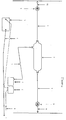
- the air circuit consists, in general, of an air generation system (compressor), air distribution pipes, non-return valves, air tank and air pressure regulators. All of the above listed parts constitute one integrated air circuit, that works automatically on regulating the designed air pressure inside vehicle tyres.
- the compressor sensor acts to detect whether there is a decrease of air pressure in one tyre or the four tyres.
- This sensor works by the battery (1) to dynamo (2), then the compressor (3) starts working to pump air to the air tank (5) through metallic pipes (4). Then air is to be distributed from the tank (5) through the air transmission metallic pipes (4) to two air pressure regulators (6), one of which is frontal, to regulate air pressure of the front tyres.
- the regulated air is being transported through pipe connection (10) to the front tyres.
- the other one is rear air regulator set to regulate air pressure of the rear tyres.
- the regulated air is being transported through a pipe connection (9) to the rear tyres.
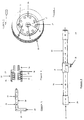
- Air is being transported through the pipe connection (10) to the base of wheel axle fixing (12). Air can be entered through a flexible hose joint (11) to the tyre axle (13), through the elastic and flexible joint (11) to air passage (19) in the tyre axle (13). Then air carries on its passage, passing from the circular motion transmission system (18) to the circular metallic pipe (20), then to air outlet (30), on which a non-return valve as regulator (6) is installed. Then air is transported within the pipe connection (28) between the non-return valve (27) and the circular metallic pipe (20).
- the non-return valve (27) and the circular metallic pipe (20) can be connected by means of a flexible joint - pipe connection (28), on both ends of which two pins are fixed to open the non-return valves between the two ends, to keep air passage between the non-return valve (27) and the circular metallic pipe (20) open.
- a flexible joint - pipe connection (28) on both ends of which two pins are fixed to open the non-return valves between the two ends, to keep air passage between the non-return valve (27) and the circular metallic pipe (20) open.
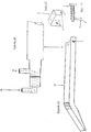
- valve (31) In emergencies, i.e. when the compressor (3), the dynamo (2) turning the compressor, breaks one of the pipes connecting air, or the breaking of one pipe intentionally by a person, the function of valve (31) will be maintaining the pressure of air equal in all tyres, due to the presence of the non-return valve (32) installed thereon.
- valve (31) function will be preventing discharge of the air present within tyres, and consequently maintaining the designed pressure specified by the manufacturer.
- a valve is also fixed on the opening (32) to discharge the surplus air, in cases of pressure increase in tyres due to the expansion of the present air because of temperature increase due to friction.
- axle (13) can be punctured from outside, without touching the differential hub, and the pattern will be like in Fig. 4.
- the hole pattern will be as in Fig. 2. If air entrance is from the side of which there is no differential hub, from the axle (13) through hole (11), the air outlet will be through the hole (30).
- a holder (36) of the flexible pipe holder (37) is designed to prevent the friction of the pipe connection (28) with the interior side of the vehicles right and left side wheel cover or even with the tyre itself. This holder assists also to prevent the detachment of the pipe connection (28) from its fixing place.
Landscapes
- Engineering & Computer Science (AREA)
- Mechanical Engineering (AREA)
- Tires In General (AREA)
Priority Applications (1)
| Application Number | Priority Date | Filing Date | Title |
|---|---|---|---|
| EP97600006A EP0890461A1 (de) | 1997-07-08 | 1997-07-08 | Druckluftkreislauf für Fahrzeuge |
Applications Claiming Priority (1)
| Application Number | Priority Date | Filing Date | Title |
|---|---|---|---|
| EP97600006A EP0890461A1 (de) | 1997-07-08 | 1997-07-08 | Druckluftkreislauf für Fahrzeuge |
Publications (1)
| Publication Number | Publication Date |
|---|---|
| EP0890461A1 true EP0890461A1 (de) | 1999-01-13 |
Family
ID=8230106
Family Applications (1)
| Application Number | Title | Priority Date | Filing Date |
|---|---|---|---|
| EP97600006A Withdrawn EP0890461A1 (de) | 1997-07-08 | 1997-07-08 | Druckluftkreislauf für Fahrzeuge |
Country Status (1)
| Country | Link |
|---|---|
| EP (1) | EP0890461A1 (de) |
Citations (2)
| Publication number | Priority date | Publication date | Assignee | Title |
|---|---|---|---|---|
| DE802377C (de) * | 1949-02-01 | 1951-02-12 | R Dr Jaeckel | Automatische Reifendruck-Kontroll- und Drucknachfuellvorrichtung fuer Lastzuege |
| EP0457028A2 (de) * | 1990-05-17 | 1991-11-21 | Equalaire Systems, Inc. | Luftkontrollsystem für Fahrzeugreifen |
-
1997
- 1997-07-08 EP EP97600006A patent/EP0890461A1/de not_active Withdrawn
Patent Citations (2)
| Publication number | Priority date | Publication date | Assignee | Title |
|---|---|---|---|---|
| DE802377C (de) * | 1949-02-01 | 1951-02-12 | R Dr Jaeckel | Automatische Reifendruck-Kontroll- und Drucknachfuellvorrichtung fuer Lastzuege |
| EP0457028A2 (de) * | 1990-05-17 | 1991-11-21 | Equalaire Systems, Inc. | Luftkontrollsystem für Fahrzeugreifen |
Similar Documents
| Publication | Publication Date | Title |
|---|---|---|
| US7880597B2 (en) | Hybrid vehicle battery information display device | |
| US20080278299A1 (en) | Vehicle brake pressure monitoring system an method | |
| CN108422917B (zh) | 一种自卸车 | |
| JPH02503662A (ja) | 自動車の機械ユニツトおよび積み荷保護装置 | |
| JP2003226207A (ja) | 車両用電源システム | |
| US6230556B1 (en) | Axle assembly integrated with a tire inflation system and an electronic recorder | |
| CN114148173A (zh) | 一种电动汽车动力电池包碰撞预警与安全保护系统及方法 | |
| CN110886799A (zh) | 一种用于半挂车鼓式制动器的衬片磨损报警装置 | |
| US7308823B2 (en) | Tire pressure control system for a vehicle | |
| EP1500528A1 (de) | Sender und Empfänger für eine Reifenzustandüberwachungsgerät | |
| CN207120624U (zh) | 一种轮胎自动监测充气系统 | |
| JPH10114207A (ja) | タイヤの空気抜け検出器 | |
| CN109572338B (zh) | 一种汽车安全监测报警系统 | |
| CN216742228U (zh) | 一种转向油罐组件和具有其的车辆 | |
| JP2002055715A (ja) | 乗員への車両状態通知システム | |
| CN200967395Y (zh) | 车辆行驶中轮胎应急充气装置 | |
| CN215154543U (zh) | 融合胎压监测的气压式防抱死制动系统 | |
| CN2741808Y (zh) | 汽车轮胎安全装置 | |
| CN221293481U (zh) | 气制动极限位置报警装置 | |
| GB2331053A (en) | Vehicle engine control during temporary tyre repair | |
| CN218750671U (zh) | 一种可视预防预警控制设备 | |
| CN216331985U (zh) | 一种汽车驾驶室无人防溜车系统 | |
| CN101195329A (zh) | 汽车行驶中轮胎应急充气装置 | |
| KR19990018375U (ko) | 자동차 타이어압 보충장치 | |
| JPH0549548U (ja) | エアタンクの水溜り警報装置 |
Legal Events
| Date | Code | Title | Description |
|---|---|---|---|
| PUAI | Public reference made under article 153(3) epc to a published international application that has entered the european phase |
Free format text: ORIGINAL CODE: 0009012 |
|
| AK | Designated contracting states |
Kind code of ref document: A1 Designated state(s): DE FR GB IT |
|
| AX | Request for extension of the european patent |
Free format text: AL;LT;LV;RO;SI |
|
| AKX | Designation fees paid |
Free format text: DE FR GB IT |
|
| 17P | Request for examination filed |
Effective date: 19990713 |
|
| 17Q | First examination report despatched |
Effective date: 20020326 |
|
| STAA | Information on the status of an ep patent application or granted ep patent |
Free format text: STATUS: THE APPLICATION IS DEEMED TO BE WITHDRAWN |
|
| 18D | Application deemed to be withdrawn |
Effective date: 20020806 |