EP0890499A1 - Système de direction des roues arrières - Google Patents
Système de direction des roues arrières Download PDFInfo
- Publication number
- EP0890499A1 EP0890499A1 EP98305443A EP98305443A EP0890499A1 EP 0890499 A1 EP0890499 A1 EP 0890499A1 EP 98305443 A EP98305443 A EP 98305443A EP 98305443 A EP98305443 A EP 98305443A EP 0890499 A1 EP0890499 A1 EP 0890499A1
- Authority
- EP
- European Patent Office
- Prior art keywords
- axial centre
- wheel steering
- movable member
- rod
- steering system
- Prior art date
- Legal status (The legal status is an assumption and is not a legal conclusion. Google has not performed a legal analysis and makes no representation as to the accuracy of the status listed.)
- Granted
Links
- 238000003754 machining Methods 0.000 description 3
- 238000005452 bending Methods 0.000 description 1
- 239000002783 friction material Substances 0.000 description 1
- 238000004519 manufacturing process Methods 0.000 description 1
- 230000002093 peripheral effect Effects 0.000 description 1
Images


Classifications
-
- B—PERFORMING OPERATIONS; TRANSPORTING
- B62—LAND VEHICLES FOR TRAVELLING OTHERWISE THAN ON RAILS
- B62D—MOTOR VEHICLES; TRAILERS
- B62D7/00—Steering linkage; Stub axles or their mountings
- B62D7/06—Steering linkage; Stub axles or their mountings for individually-pivoted wheels, e.g. on king-pins
- B62D7/14—Steering linkage; Stub axles or their mountings for individually-pivoted wheels, e.g. on king-pins the pivotal axes being situated in more than one plane transverse to the longitudinal centre line of the vehicle, e.g. all-wheel steering
- B62D7/15—Steering linkage; Stub axles or their mountings for individually-pivoted wheels, e.g. on king-pins the pivotal axes being situated in more than one plane transverse to the longitudinal centre line of the vehicle, e.g. all-wheel steering characterised by means varying the ratio between the steering angles of the steered wheels
- B62D7/1581—Steering linkage; Stub axles or their mountings for individually-pivoted wheels, e.g. on king-pins the pivotal axes being situated in more than one plane transverse to the longitudinal centre line of the vehicle, e.g. all-wheel steering characterised by means varying the ratio between the steering angles of the steered wheels characterised by comprising an electrical interconnecting system between the steering control means of the different axles
-
- B—PERFORMING OPERATIONS; TRANSPORTING
- B62—LAND VEHICLES FOR TRAVELLING OTHERWISE THAN ON RAILS
- B62D—MOTOR VEHICLES; TRAILERS
- B62D5/00—Power-assisted or power-driven steering
- B62D5/04—Power-assisted or power-driven steering electrical, e.g. using an electric servo-motor connected to, or forming part of, the steering gear
- B62D5/0421—Electric motor acting on or near steering gear
- B62D5/0424—Electric motor acting on or near steering gear the axes of motor and final driven element of steering gear, e.g. rack, being parallel
- B62D5/0427—Electric motor acting on or near steering gear the axes of motor and final driven element of steering gear, e.g. rack, being parallel the axes being coaxial
-
- B—PERFORMING OPERATIONS; TRANSPORTING
- B62—LAND VEHICLES FOR TRAVELLING OTHERWISE THAN ON RAILS
- B62D—MOTOR VEHICLES; TRAILERS
- B62D5/00—Power-assisted or power-driven steering
- B62D5/04—Power-assisted or power-driven steering electrical, e.g. using an electric servo-motor connected to, or forming part of, the steering gear
- B62D5/0442—Conversion of rotational into longitudinal movement
- B62D5/0445—Screw drives
-
- Y—GENERAL TAGGING OF NEW TECHNOLOGICAL DEVELOPMENTS; GENERAL TAGGING OF CROSS-SECTIONAL TECHNOLOGIES SPANNING OVER SEVERAL SECTIONS OF THE IPC; TECHNICAL SUBJECTS COVERED BY FORMER USPC CROSS-REFERENCE ART COLLECTIONS [XRACs] AND DIGESTS
- Y10—TECHNICAL SUBJECTS COVERED BY FORMER USPC
- Y10T—TECHNICAL SUBJECTS COVERED BY FORMER US CLASSIFICATION
- Y10T74/00—Machine element or mechanism
- Y10T74/18—Mechanical movements
- Y10T74/18568—Reciprocating or oscillating to or from alternating rotary
- Y10T74/18576—Reciprocating or oscillating to or from alternating rotary including screw and nut
- Y10T74/18664—Shaft moves through rotary drive means
-
- Y—GENERAL TAGGING OF NEW TECHNOLOGICAL DEVELOPMENTS; GENERAL TAGGING OF CROSS-SECTIONAL TECHNOLOGIES SPANNING OVER SEVERAL SECTIONS OF THE IPC; TECHNICAL SUBJECTS COVERED BY FORMER USPC CROSS-REFERENCE ART COLLECTIONS [XRACs] AND DIGESTS
- Y10—TECHNICAL SUBJECTS COVERED BY FORMER USPC
- Y10T—TECHNICAL SUBJECTS COVERED BY FORMER US CLASSIFICATION
- Y10T74/00—Machine element or mechanism
- Y10T74/18—Mechanical movements
- Y10T74/18568—Reciprocating or oscillating to or from alternating rotary
- Y10T74/18576—Reciprocating or oscillating to or from alternating rotary including screw and nut
- Y10T74/18712—Contamination related
- Y10T74/1872—Imperforate enclosure
Definitions
- the present invention relates to a rear-wheel steering system of a motor vehicle.
- a rear-wheel steering system of a motor vehicle is disclosed in, for example, Japanese Patent Application Laid-Open 7-215226.
- This rear-wheel steering system is provided with a nut member contained in a housing and connected to an electric motor through a planetary gear unit, and a rod having an external thread portion in mesh with an internal thread portion of the nut member.
- the rod is laterally moved across a width of the vehicle by rotation of the electric motor so as to steer rear wheels connected thereto,.
- the generally employed rear-wheel steering system as described above has a nut member 120 for converting a rotational motion of an electric motor into an axial straight motion of a rod 110.
- the nut member 120 has an internal thread portion 120a, which is engaged with an external thread portion 110a of the rod 110.
- each dimension thereof is likely to vary depending on the individual machining process condition.
- looseness between the internal thread portion 120a and the external thread portion 110a is unavoidably generated. Such looseness may cause the wheel of the running vehicle to slightly vibrate, leading to noise from the thread portions in mesh with each other.
- an object of the present invention is to provide a rear-wheel steering system in which a looseness between internal and external thread portions in mesh with each other is compensated for reducing the noise generated in the meshed thread portions without raising the costs of producing the threaded portions.
- the present invention provides a rear-wheel steering system including an electric motor for generating a rotational force, a rotational member connected to the electric motor and rotated thereby, a movable member axially moved by rotation of the rotational member for steering rear wheels of a vehicle to which both ends of the movable member are connected, an internal thread portion provided with the rotational member, and an external thread portion provided with the movable member in mesh with the internal thread portion.
- the external thread portion is not allowed to rotate.
- the internal and external thread portions are engaged such that each axial centre thereof is off-centred.
- the internal thread portion of the rotational member and the external thread portion of the movable member, meshed with each other, are off-centred. This arrangement compensates for the looseness between the thread portions in mesh with each other, thus reducing the noise during running of the vehicle at a low cost.
- the present invention is further provided with a first support portion for radially supporting the rotational member, a second support portion for radially supporting the movable member, and a housing in which each axial centre of the first support portion and the second support portion is off-centred.
- the housing is structured such that each axial centre of the first support portion radially supporting the rotational member and the second support portion radially supporting the movable member is off-centred, the internal thread portion of the rotational member and the external thread portion of the movable member, thus, can easily be off-centred.
- the present invention is further provided with a first support portion for radially supporting the rotational member, and a housing containing a second support portion for radially supporting the movable member.
- a slide portion supported by the second support portion of the movable member and an axial centre of the external thread portion are off-centred. As the slide portion supported by the second support portion of the movable member and the axial centre of the external thread portion are off-centred, the internal thread portion of the rotational member and the external thread portion of the movable member can easily be off-centred.
- Fig. 1 is a cross-sectional view of a rear-wheel steering system according to the present invention.
- a housing 1 is defined by a cylindrical portion la, a conical portion 1b fitted therewith, and a cylindrical portion 1c.
- the cylindrical portion la has a diameter larger than that of the cylindrical portion lc.
- the cylindrical portion la contains a brushless motor 3 therein.
- a hollow rotational shaft 5 is disposed to pass through the inside of the brushless motor 3.
- the hollow rotational shaft 5 is rotatably supported by the inner periphery of the cylindrical portion 1c with a bearing 7 as represented on the left-hand side of Fig. 1. Meanwhile the hollow rotational shaft 5 is rotatably supported by the inner periphery of the cylindrical portion la with a bearing 9 as represented on the right-hand side of Fig. 1.
- the brushless motor 3 is connected to a power source (not shown) of a motor vehicle through a harness 11.
- the hollow rotational shaft 5 is connected to a planetary gear unit 13 disposed in series at two stages.
- An output side of the second stage of the planetary gear 13 is connected to a nut member 15.
- the nut member 15 is attached to the housing 1 such that the nut member is not permitted to move linearly with respect to the housing.
- the nut member 15 is rotatably supported by an inner periphery lab of the cylindrical portion la with a bearing 17, and is thus rotatable with respect to the housing 1.
- the rotation of the brushless motor 3 is decelerated by the planetary gear unit 13, which is transmitted to the nut member 15.
- the brushless motor 3 causes the nut member 15 to rotate with respect to the stationary conical portion 1b of the housing 1.
- a spline portion 19a located at a right end of a rod 19 as shown in Fig. 1 is fitted with a support portion 1ba having a spline provided for the conical portion 1b such that the spline portion 19a is slidably supported by the conical portion 1b axially. That is, as shown in Fig. 4, the conical portion 1b, or an insert positioned therein, has a plurality of teeth that extend parallel with the longitudinal axis of the rod 19 and that mate with corresponding parallel teeth on the rod 19.
- relative linear movement can occur between the rod 19 and the conical portion 1b, but rotational movement between the rod 19 and the conical portion 1b is prevented.
- a slide portion 19b of the rod 19 is located at a left end of the rod 19 as shown in Fig. 1 and is fitted with a bushing 1ca made of a low friction material.
- the bushing lca can be integral with the housing 1 or can be a separate item attached to the housing 1.
- the bushing lca is connected to the cylindrical portion 1c of the housing 1.
- the bushing lca is received by the cylindrical portion 1c and the bushing receives the slide portion 19b.
- the slide portion 19b is slidably supported by the bushing lca located in cylindrical portion 1c axially.
- the rod 19, thus, is slidably axially supported by the cylindrical portion 1c, and relative linear movement can occur between the rod 19 and the bushing lca (and cylindrical portion 1c).
- the bushing 1ca and the slide portion 19b are configured such that rotational movement between the bushing 1ca and the slide portion 19b is prevented. Accordingly, the rod 19 is supported by the housing 1 non-rotatably.
- the rod 19 has an external thread portion 19c disposed at a position apart from its right end by approximately 1/4 of the whole length thereof as shown in Fig. 1.
- the external thread portion 19c is engaged with the internal thread portion 15a of the nut member 15, by which the rotational motion transmitted to the nut member 15 is converted into a straight motion of the rod 19.
- male threads on the rod 19 are received by female threads on the nut member 15. Because the nut member 15 is permitted to rotate but is not permitted to move linearly, rotation of the nut member 15 with respect to the rod 19 will cause the rod to move linearly.
- Both ends of the rod 19 are connected to tie rods 23a, 23b through universal joints 21a,21b respectively.
- the tie rods 23a,23b are connected to rear wheels (not shown) of the motor vehicle.
- the rotation of the brushless motor 3 moves the rod 19 axially to steer rear wheels of the vehicle.
- the support portion lba of the conical portion 1b and the bushing 1ca of the cylindrical portion 1c each have a centre that is off-centre with respect to the axial centre of the cylindrical inner periphery lab of the cylindrical portion la. Accordingly, the axial centre of the internal thread portion 15a of the nut member 15 supported by the support portion lab is eccentric with respect to the axial centre of the external thread portion 19c of the rod 19 supported by the bushing lca. That is, the axis of the rod 19 is located away from the centre axis of cylindrical inner periphery lab of the housing and is, thus, also located away from the centre axis of the nut member 15. For example, referring to Fig. 2, the external thread portion 19c is eccentrically disposed upward of the internal thread portion 15a. Thus, the looseness between the meshed internal and external thread portions shown in Fig. 2 is compensated.
- the rod 19 continuously receives a reaction force or bending moment exerted from the nut member 15, which prevents the rod 19 from substantially vibrating with respect to the nut member 15.
- each of the axis of the spline portion 19a and slide portion 19b of the rod 19 is also eccentrically disposed downward with respect to each of the centre axis of the support portion 1ba of the conical portion 1b and the bushing 1ca of the cylindrical portion 1c, as shown in Fig. 4, by the reaction force from the nut member 15 to the rod 19.
- the eccentricity of the axes of the rod 19 and the housing 1 can be greater or lesser at the spline portion 19a than at the threaded portion 19c.
- the looseness in the peripheral direction between the spline portion 19a of the rod 19 and the spline of the support portion lba of the conical portion 1b can be compensated to prevent the rod 19 from rotating. Because one embodiment of the present invention strives to prevent at least the thread portions 15a, 19c from vibrating, vehicle noise and vibrations are lessened. The rotation of the brushless motor 3, thus, can be efficiently applied to perform rear-wheel steering.
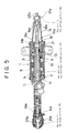
- the present invention may be structured such that the axial centre of the external thread portion 19c is off-centre with respect to the axial centre of the spline portion 19a and the axial centre of the slide portion 19b of the rod 19 as shown in Fig 5, without causing the axial centre of the support portion lba of the conical portion 1b and the axial centre of the bushing lca of the cylindrical portion 1c to be eccentrically off-centre with respect to the inner periphery lab of the housing 1.
- the above-described advantages may be obtained by this structure.
Landscapes
- Engineering & Computer Science (AREA)
- Chemical & Material Sciences (AREA)
- Combustion & Propulsion (AREA)
- Transportation (AREA)
- Mechanical Engineering (AREA)
- Power Steering Mechanism (AREA)
- Steering-Linkage Mechanisms And Four-Wheel Steering (AREA)
Applications Claiming Priority (3)
| Application Number | Priority Date | Filing Date | Title |
|---|---|---|---|
| JP182588/97 | 1997-07-08 | ||
| JP09182588A JP3108389B2 (ja) | 1997-07-08 | 1997-07-08 | 後輪操舵装置 |
| JP18258897 | 1997-07-08 |
Publications (2)
| Publication Number | Publication Date |
|---|---|
| EP0890499A1 true EP0890499A1 (fr) | 1999-01-13 |
| EP0890499B1 EP0890499B1 (fr) | 2002-11-06 |
Family
ID=16120925
Family Applications (1)
| Application Number | Title | Priority Date | Filing Date |
|---|---|---|---|
| EP98305443A Expired - Lifetime EP0890499B1 (fr) | 1997-07-08 | 1998-07-08 | Système de direction des roues arrières |
Country Status (4)
| Country | Link |
|---|---|
| US (1) | US6041886A (fr) |
| EP (1) | EP0890499B1 (fr) |
| JP (1) | JP3108389B2 (fr) |
| DE (1) | DE69809138T2 (fr) |
Cited By (5)
| Publication number | Priority date | Publication date | Assignee | Title |
|---|---|---|---|---|
| DE10032120A1 (de) * | 1999-12-17 | 2001-07-19 | Zf Lenksysteme Gmbh | Lenkvorrichtung für Kraftfahrzeuge |
| US6810985B1 (en) | 1999-12-17 | 2004-11-02 | Zf Lenksysteme Gmbh | Steering device for a vehicle |
| EP1538066A1 (fr) | 2003-12-02 | 2005-06-08 | Renault | Actionneur pour essieu de véhicule automobile comprenant un moteur électrique à rotor extérieur et essieu de véhicule automobile commandé par un tel actionneur |
| EP2484577A3 (fr) * | 2011-02-08 | 2013-01-09 | Aisin Seiki Kabushiki Kaisha | Dispositif de direction de roue arrière de véhicule |
| IT201700004014A1 (it) * | 2017-01-16 | 2018-07-16 | Ognibene Power Spa | Sistema di sterzatura |
Families Citing this family (17)
| Publication number | Priority date | Publication date | Assignee | Title |
|---|---|---|---|---|
| JPH0554319U (ja) * | 1991-12-26 | 1993-07-20 | 中国パール販売株式会社 | 海苔巻おにぎり包装具 |
| JP2001180512A (ja) * | 1999-10-13 | 2001-07-03 | Honda Motor Co Ltd | 後輪操舵装置の制御装置 |
| DE10044733A1 (de) * | 2000-09-09 | 2002-03-21 | Schaeffler Waelzlager Ohg | Vorschubeinheit |
| US6540043B2 (en) * | 2001-06-21 | 2003-04-01 | General Motors Corporation | Vehicle steering system with electronic power regulation unit for limiting the steering angle of rear wheels at high speeds |
| US6560524B2 (en) | 2001-09-26 | 2003-05-06 | General Motors Corporation | Integration of rear wheel steering with vehicle stability enhancement system |
| KR100746687B1 (ko) * | 2002-07-29 | 2007-08-06 | 주식회사 만도 | 차량용 전동 파워스티어링장치 |
| US6813552B2 (en) | 2002-11-18 | 2004-11-02 | General Motors Corporation | Method and apparatus for vehicle stability enhancement system |
| US6865468B2 (en) | 2002-11-26 | 2005-03-08 | General Motors Corporation | Method and apparatus for vehicle stability enhancement system |
| US6819998B2 (en) * | 2002-11-26 | 2004-11-16 | General Motors Corporation | Method and apparatus for vehicle stability enhancement system |
| US6968261B2 (en) * | 2003-01-03 | 2005-11-22 | General Motors Corporation | Method and apparatus for vehicle stability enhancement system |
| US6879898B2 (en) * | 2003-01-03 | 2005-04-12 | General Motors Corporation | Method and apparatus for vehicle integrated chassis control system |
| US20050223986A1 (en) | 2004-04-12 | 2005-10-13 | Choi Soo Y | Gas diffusion shower head design for large area plasma enhanced chemical vapor deposition |
| JP2009113730A (ja) * | 2007-11-08 | 2009-05-28 | Aisin Seiki Co Ltd | 車両の後輪操舵装置 |
| JP2009292433A (ja) * | 2008-06-09 | 2009-12-17 | Aisin Seiki Co Ltd | 車両の後輪操舵装置 |
| JP6094384B2 (ja) * | 2013-05-29 | 2017-03-15 | アイシン精機株式会社 | 車両の後輪操舵装置 |
| KR20150078780A (ko) * | 2013-12-31 | 2015-07-08 | 현대자동차주식회사 | 후륜 조향장치의 스티어링 링키지 구조 |
| JP2016084011A (ja) * | 2014-10-24 | 2016-05-19 | アイシン精機株式会社 | 車両の後輪操舵装置 |
Citations (1)
| Publication number | Priority date | Publication date | Assignee | Title |
|---|---|---|---|---|
| FR2605280A1 (fr) * | 1986-10-20 | 1988-04-22 | Honda Motor Co Ltd | Dispositif de braquage des roues arriere pour vehicule a quatre roues directrices |
Family Cites Families (9)
| Publication number | Priority date | Publication date | Assignee | Title |
|---|---|---|---|---|
| US3730016A (en) * | 1971-06-14 | 1973-05-01 | Continental Can Co | Friction drive differential screw |
| GB2107263B (en) * | 1981-07-28 | 1985-01-16 | Honda Motor Co Ltd | Vehicular steering system |
| US5284220A (en) * | 1988-07-25 | 1994-02-08 | Atsugi Unisia Corporation | Pressure control valve assembly for hydraulic circuit and automotive rear wheel steering system utilizing the same |
| JPH03136975A (ja) * | 1989-10-24 | 1991-06-11 | Atsugi Unisia Corp | 前後輪操舵車の後輪操舵装置 |
| US5086861A (en) * | 1990-04-06 | 1992-02-11 | Peterson Donald W | Electric rear wheel steering actuator |
| US5487439A (en) * | 1992-04-28 | 1996-01-30 | Kayaba Industry Co., Ltd. | Rear wheel steering device |
| JP2553012B2 (ja) * | 1993-06-30 | 1996-11-13 | リードライト・エスエムアイ株式会社 | 薄膜磁気ヘッド |
| JP3206783B2 (ja) * | 1993-08-04 | 2001-09-10 | アイシン精機株式会社 | 車両の後輪操舵装置 |
| JPH07285450A (ja) * | 1994-04-20 | 1995-10-31 | Aisin Seiki Co Ltd | リニアアクチュエ−タ |
-
1997
- 1997-07-08 JP JP09182588A patent/JP3108389B2/ja not_active Expired - Lifetime
-
1998
- 1998-07-07 US US09/110,972 patent/US6041886A/en not_active Expired - Lifetime
- 1998-07-08 DE DE69809138T patent/DE69809138T2/de not_active Expired - Lifetime
- 1998-07-08 EP EP98305443A patent/EP0890499B1/fr not_active Expired - Lifetime
Patent Citations (1)
| Publication number | Priority date | Publication date | Assignee | Title |
|---|---|---|---|---|
| FR2605280A1 (fr) * | 1986-10-20 | 1988-04-22 | Honda Motor Co Ltd | Dispositif de braquage des roues arriere pour vehicule a quatre roues directrices |
Cited By (7)
| Publication number | Priority date | Publication date | Assignee | Title |
|---|---|---|---|---|
| DE10032120A1 (de) * | 1999-12-17 | 2001-07-19 | Zf Lenksysteme Gmbh | Lenkvorrichtung für Kraftfahrzeuge |
| US6810985B1 (en) | 1999-12-17 | 2004-11-02 | Zf Lenksysteme Gmbh | Steering device for a vehicle |
| EP1538066A1 (fr) | 2003-12-02 | 2005-06-08 | Renault | Actionneur pour essieu de véhicule automobile comprenant un moteur électrique à rotor extérieur et essieu de véhicule automobile commandé par un tel actionneur |
| EP2484577A3 (fr) * | 2011-02-08 | 2013-01-09 | Aisin Seiki Kabushiki Kaisha | Dispositif de direction de roue arrière de véhicule |
| US8875835B2 (en) | 2011-02-08 | 2014-11-04 | Aisin Seiki Kabushiki Kaisha | Vehicular rear wheel steering device |
| IT201700004014A1 (it) * | 2017-01-16 | 2018-07-16 | Ognibene Power Spa | Sistema di sterzatura |
| EP3348452A1 (fr) * | 2017-01-16 | 2018-07-18 | Ognibene Power S.P.A. | Système de direction |
Also Published As
| Publication number | Publication date |
|---|---|
| US6041886A (en) | 2000-03-28 |
| DE69809138D1 (de) | 2002-12-12 |
| JP3108389B2 (ja) | 2000-11-13 |
| EP0890499B1 (fr) | 2002-11-06 |
| JPH1120713A (ja) | 1999-01-26 |
| DE69809138T2 (de) | 2003-07-24 |
Similar Documents
| Publication | Publication Date | Title |
|---|---|---|
| EP0890499B1 (fr) | Système de direction des roues arrières | |
| EP2226235B1 (fr) | Direction assistée électrique | |
| US7278334B2 (en) | Electric power steering apparatus | |
| US9683639B2 (en) | Reaction force actuator and steering device | |
| EP0931714A1 (fr) | Système de direction assistée électrique avec réducteur de vitesse | |
| JP2019100439A (ja) | 補助装置 | |
| EP2052946B1 (fr) | Dispositif de direction pour véhicule automobile | |
| EP1559631B1 (fr) | Systeme de guidage | |
| JP2016203758A (ja) | 車両の後輪操舵装置 | |
| EP0896917B1 (fr) | Dispositif de direction assistee | |
| EP2090495A1 (fr) | Dispositif de direction de vehicule | |
| EP3486139B1 (fr) | Dispositif de direction | |
| US11293524B2 (en) | Vehicle drive device | |
| JPH1134888A (ja) | 電動式パワーステアリング装置 | |
| JP2024045301A (ja) | 操舵補助装置 | |
| JP2001219856A (ja) | 直線的に駆動されるアクチュエーター・シャフトを有する自動車用操舵システム | |
| JPH07237551A (ja) | 電動式パワーステアリング装置 | |
| JP2676286B2 (ja) | 内接噛合形遊星歯車減速機構を使用した制御装置 | |
| JP2004291741A (ja) | 電動式パワーステアリング装置 | |
| JP2008183934A (ja) | 電動パワーステアリング装置 | |
| EP3012174A1 (fr) | Dispositif de braquage des roues arrière d'un véhicule | |
| JP2001315655A (ja) | 電動パワーステアリング装置 | |
| JP2023102403A (ja) | 電動パワーステアリング装置 | |
| JP2000016314A (ja) | 電動式パワーステアリング装置 | |
| KR20250143034A (ko) | 차량용 조향 장치 |
Legal Events
| Date | Code | Title | Description |
|---|---|---|---|
| PUAI | Public reference made under article 153(3) epc to a published international application that has entered the european phase |
Free format text: ORIGINAL CODE: 0009012 |
|
| AK | Designated contracting states |
Kind code of ref document: A1 Designated state(s): DE FR GB |
|
| AX | Request for extension of the european patent |
Free format text: AL;LT;LV;MK;RO;SI |
|
| 17P | Request for examination filed |
Effective date: 19990123 |
|
| AKX | Designation fees paid |
Free format text: DE FR GB |
|
| 17Q | First examination report despatched |
Effective date: 20010529 |
|
| GRAG | Despatch of communication of intention to grant |
Free format text: ORIGINAL CODE: EPIDOS AGRA |
|
| GRAG | Despatch of communication of intention to grant |
Free format text: ORIGINAL CODE: EPIDOS AGRA |
|
| GRAH | Despatch of communication of intention to grant a patent |
Free format text: ORIGINAL CODE: EPIDOS IGRA |
|
| GRAH | Despatch of communication of intention to grant a patent |
Free format text: ORIGINAL CODE: EPIDOS IGRA |
|
| GRAA | (expected) grant |
Free format text: ORIGINAL CODE: 0009210 |
|
| AK | Designated contracting states |
Kind code of ref document: B1 Designated state(s): DE FR GB |
|
| REG | Reference to a national code |
Ref country code: GB Ref legal event code: FG4D |
|
| REF | Corresponds to: |
Ref document number: 69809138 Country of ref document: DE Date of ref document: 20021212 |
|
| ET | Fr: translation filed | ||
| PLBE | No opposition filed within time limit |
Free format text: ORIGINAL CODE: 0009261 |
|
| STAA | Information on the status of an ep patent application or granted ep patent |
Free format text: STATUS: NO OPPOSITION FILED WITHIN TIME LIMIT |
|
| 26N | No opposition filed |
Effective date: 20030807 |
|
| REG | Reference to a national code |
Ref country code: FR Ref legal event code: PLFP Year of fee payment: 19 |
|
| REG | Reference to a national code |
Ref country code: FR Ref legal event code: PLFP Year of fee payment: 20 |
|
| PGFP | Annual fee paid to national office [announced via postgrant information from national office to epo] |
Ref country code: FR Payment date: 20170613 Year of fee payment: 20 |
|
| PGFP | Annual fee paid to national office [announced via postgrant information from national office to epo] |
Ref country code: DE Payment date: 20170705 Year of fee payment: 20 Ref country code: GB Payment date: 20170705 Year of fee payment: 20 |
|
| REG | Reference to a national code |
Ref country code: DE Ref legal event code: R071 Ref document number: 69809138 Country of ref document: DE |
|
| REG | Reference to a national code |
Ref country code: GB Ref legal event code: PE20 Expiry date: 20180707 |
|
| PG25 | Lapsed in a contracting state [announced via postgrant information from national office to epo] |
Ref country code: GB Free format text: LAPSE BECAUSE OF EXPIRATION OF PROTECTION Effective date: 20180707 |