EP0890505A1 - Zweirad-Radnaben-Montagevorrichtung - Google Patents
Zweirad-Radnaben-Montagevorrichtung Download PDFInfo
- Publication number
- EP0890505A1 EP0890505A1 EP97450018A EP97450018A EP0890505A1 EP 0890505 A1 EP0890505 A1 EP 0890505A1 EP 97450018 A EP97450018 A EP 97450018A EP 97450018 A EP97450018 A EP 97450018A EP 0890505 A1 EP0890505 A1 EP 0890505A1
- Authority
- EP
- European Patent Office
- Prior art keywords
- tube
- hub
- cassette
- frame
- mounting device
- Prior art date
- Legal status (The legal status is an assumption and is not a legal conclusion. Google has not performed a legal analysis and makes no representation as to the accuracy of the status listed.)
- Granted
Links
- 238000013519 translation Methods 0.000 claims description 6
- 230000000903 blocking effect Effects 0.000 claims description 4
- 230000000149 penetrating effect Effects 0.000 abstract 1
- 208000031968 Cadaver Diseases 0.000 description 5
- 238000006073 displacement reaction Methods 0.000 description 2
- 240000008042 Zea mays Species 0.000 description 1
- 238000013459 approach Methods 0.000 description 1
- 238000010276 construction Methods 0.000 description 1
- 238000011161 development Methods 0.000 description 1
- 238000012423 maintenance Methods 0.000 description 1
- 230000000717 retained effect Effects 0.000 description 1
- 238000005728 strengthening Methods 0.000 description 1
- 230000009897 systematic effect Effects 0.000 description 1
- 238000012549 training Methods 0.000 description 1
- 230000017105 transposition Effects 0.000 description 1
- 238000011144 upstream manufacturing Methods 0.000 description 1
Images


Classifications
-
- B—PERFORMING OPERATIONS; TRANSPORTING
- B60—VEHICLES IN GENERAL
- B60B—VEHICLE WHEELS; CASTORS; AXLES FOR WHEELS OR CASTORS; INCREASING WHEEL ADHESION
- B60B27/00—Hubs
- B60B27/02—Hubs adapted to be rotatably arranged on axle
- B60B27/023—Hubs adapted to be rotatably arranged on axle specially adapted for bicycles
- B60B27/026—Hubs adapted to be rotatably arranged on axle specially adapted for bicycles comprising quick release devices
-
- B—PERFORMING OPERATIONS; TRANSPORTING
- B62—LAND VEHICLES FOR TRAVELLING OTHERWISE THAN ON RAILS
- B62K—CYCLES; CYCLE FRAMES; CYCLE STEERING DEVICES; RIDER-OPERATED TERMINAL CONTROLS SPECIALLY ADAPTED FOR CYCLES; CYCLE AXLE SUSPENSIONS; CYCLE SIDE-CARS, FORECARS, OR THE LIKE
- B62K25/00—Axle suspensions
- B62K25/02—Axle suspensions for mounting axles rigidly on cycle frame or fork, e.g. adjustably
-
- B—PERFORMING OPERATIONS; TRANSPORTING
- B62—LAND VEHICLES FOR TRAVELLING OTHERWISE THAN ON RAILS
- B62K—CYCLES; CYCLE FRAMES; CYCLE STEERING DEVICES; RIDER-OPERATED TERMINAL CONTROLS SPECIALLY ADAPTED FOR CYCLES; CYCLE AXLE SUSPENSIONS; CYCLE SIDE-CARS, FORECARS, OR THE LIKE
- B62K2206/00—Quick release mechanisms adapted for cycles
Definitions
- the present invention relates to a device for mounting the wheel, especially rear of a two-wheeler so as to allow disassembly in leaving the chain in place on its sprocket.
- two-wheeler is used wisely because the present invention is described in application to a bicycle for the sake of simplification but is found applicable by direct transposition to a motorcycle, to the number of pinions since the bike only has one crown on the back instead of one sprocket cassette.
- the rear wheel of a bicycle includes a hub on the edges from which are fixed the spokes which support the rim.
- This hub includes known manner an inner shaft with interposed bearings, both ends of this tree coming to be fixed on the ends of the frame of the bicycle, in housing provided for this purpose.
- the shaft is generally held in place by fastening means fast, eccentric.
- the derailleur is also fixed on the frame, at the level of this shaft, in kind of stay on the frame when the wheel is removed.
- the chain is arranged between a tray or a set of trays and a pinion cassette, this cassette being integral in rotation with the hub with means of freewheeling this pinion cassette relative to said hub.
- the present invention provides a device for mounting a rear wheel hub which allows disassembly of the wheel while leaving places the pinion cassette, which retains the resistance of the the prior art, which avoids the increase in the number of parts, which is directly adaptable to the rear wheels of existing two-wheelers, which is of a certain reliability and which avoids any untimely withdrawal of the wheel even in case of incomplete reassembly of the device.
- a freewheel mechanism is arranged either in the cylindrical hub body or in the cassette body.
- the connecting means comprise a connecting tube designed to slide in the first and second half-tubes between at least one first position in which the connecting tube is retracted inside the first half-tube and a second position in which the connecting tube is protruding from the first half-tube and enters the second half-tube when the first and second tubes are aligned.
- the connecting tube comprises a closed light provided to receive a pin secured to the means of maneuver.
- the connecting tube comprises at minus a rectilinear opening light with a recess, provided for cooperate with at least one pin integral with the second half-tube.
- the maneuvering means comprise an axis of central operation, integral with the locking means and movable in translation and in rotation relative to the first half-tube.
- the removable means for rotationally connecting the cassette body and the hub cylindrical body include a hub side guide Vee and a cassette side adapter.
- the adapter is triangular in shape.
- This device also comprises elastic return means for the connecting means in the connecting position and retaining means at soft notched friction of the operating means relative to the first half tube.
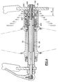
- FIG. 1A a hub 10 with spokes 12 has been shown. connected to a rim, not shown for clarity of the drawing, a cassette 14 to sprockets, a freewheel 16, a bicycle frame 18 and fixing means 20 fast.
- the hub comprises a cylindrical part 22 of revolution with side wings 24 provided with holes 26 provided to receive the ends of the rays.
- This hub further comprises a half-tube 28, inside left, in taking into account the direction of movement.
- a pair of bearings 30 ensures the free rotation of the cylindrical part 22 of revolution relative to this half-tube 28, interior left.
- a seal 32 seals on the left side.
- This tube 28, inside left protrudes outside the part cylindrical of the hub to cooperate by a shoulder 34 with the frame 18, usually in a slot 36.
- the pinion cassette 14 comprises a cassette body 38 with grooves 40 into which slide internal teeth 41 of the pinions 42 to form a stack, spacing and thickness of each sprockets are well known and suitable for forming given stacks whose characteristics are well known.
- a nut 44 locks the stack on the body 38 of cassette.
- This cassette body 38 is mounted coaxially on a half-tube 46, inside right.
- This half-tube 46, right interior, has a shoulder 48 provided to cooperate with a slot 50, made in the frame 18, right side.
- a nut 52 secures the half-tube 46, right interior on the frame.
- a pair of bearings 54 with the corresponding locking circlips ensure free rotation of the cassette body 38 relative to the half-tube 46, inside right.
- the freewheel 16 comprises for example in known manner a crown 56 internal with inclined notches, integral in rotation with the body 38 of cassette and free in translation thanks to grooves 58.
- a spring 60 of reminder tends to push this crown 56 against a ring 62 whose face in opposite also includes notches provided to cooperate with those of the crown, in the direction of training.
- the inclined notches of the crown 56 escape on the notches of the ring 62, ensuring disengagement.
- the ring 62 is also mounted free to rotate relative to the half-tube 46, right interior, thanks to a bearing 64.
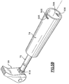
- the ring 62 further comprises on its outer periphery a adapter 66, leading, machined with said ring.
- This adapter is better represented and more visible in Figures 2 and 3.
- This adapter 66 has a triangular profile with truncated vertices 68, preferably registered in a circle.
- This triangle are designed to cooperate with a Receiving V 70 carried by the cylindrical body 22 of the hub.
- the two inner half-tubes left 28 and right 46 have a length adapted so that they abut when the device is mounted as shown in Figure 1A.
- connecting means 72 comprise a connecting tube 74 which comes be housed smoothly, coaxially, inside the two half-tubes 28 and 46 and a central operating axis 75.
- the connecting tube 74 includes first and second lumens closed 76 and 78 respectively, each provided with a recess of blocking 80 and 82.
- the length of the first light is y while the length of the second light is x .
- the second light 78 receives a guide pin 84, in this case a screw 86, integral with the half-tube 28, inside left in which the tube 74 link is likely to slide.
- the operating axis 75 has a length such that it projects from both sides and on the other side of frame 18, outside.
- This operating axis is equipped on the left side with means 20 for quick clamping of known type, lever and eccentric and right side of a groove 86 provided to receive a clip 88.
- This operating axis 75 further comprises a pin 90 transverse arranged at a distance from the end.
- This operating axis is such that, once the device according to the invention in place, its straight end is located at a distance y from the end of the connecting tube 74.
- the length of the connecting tube 74 is such that the length of overlap with the straight half-tube is x .
- the length of this connecting tube is defined on the left so that there remains a free distance x between this connecting tube and the end of the left half-tube.
- the body 38 of the pinion cassette 42 is fixed to the frame 18 at nut 52.
- the ring 62 of the freewheel 16 is free to rotate as well as the adapter 66 which it carries, thanks to the bearing 64, which allows it to be oriented in any angular position.
- the quick fastening means 20 are open and the pin 75 is removed on the left with respect to the cylindrical hub body 22 and therefore with respect to the half-tube 28, interior left.
- the connecting tube 74 is in perfect superposition with the half-tube 28, inside left, without protruding beyond the end right of the cylindrical hub body 22. Alone is protruding, by construction, the guide 70.
- the user approaches the rear wheel and follows the V 70 guide on adapter 66 by matching this Vé with one of the vertices 68 of this adapter. This maneuver is facilitated by the fact that the vertices are truncated so that the adapter self-orientates as soon as the wheel is inserted.
- the user translates the axle 75 by maneuvering fast fixing means. To do this, he first slightly rotate the axis so as to release the recess 82 from the light 78 of the connecting tube 74 outside the pin 84. Indeed, the half-tube 28, inside left is immobilized in rotation in the slot 36, easily by realization of a flat. Then he just has to push lightly, if necessary is since a first spring 92 is provided, interposed between the end left of the half-tube 28, inside left and a washer 94, blocked by a retaining rings 95.
- the connecting tube 74 moves and penetrates by a length x into the half-tube 46, right interior.
- a second spring 96 of lower stiffness than the first, interposed between the washer 94 and the pin 90 ensures this displacement in addition to the thrust of the user to subject the axis 75 to a translation y , so that the end of this axis projects beyond the end of the half-tube 46, right interior, it then suffices to clip or pin this axis to ensure the locking in translation of the axis 75. invention.
- the wheel is assembled.
- Disassembly is carried out by carrying out the different stages in order opposite of the one just described.
- the connecting tube comprises first and second circlips 400 and 402, arranged to release a stroke y between the two.
- a nut 404 and a lock nut 406 are screwed onto the axis 75, the end of which is threaded for this purpose.
- the nut 404 with the rod can slide freely between the two circlips, on the defined stroke.
- the right end of the half-tube 46, inside right, is threaded to receive by screwing the end of axis 75.
- the user maintains the operating means separated to the left to maintain the nut 404 against the first circlip 400 and thus avoid the protrusion of the connecting tube 74 relative to the half-tube 28, inside left during of the introduction.
- the user then translates the axis 75 in a single movement which places the nut against the second circlip 402, after displacement over a length y , then translates the connecting tube over a length x , at the same time as the axis 75 is screwed into the end of the half-tube 46, right interior.
- FIG. 5A a so-called pin variant is shown.
- the identical elements have the same references,
- the half-tube 46 inside right, includes a pin 500, transverse, in the immediate vicinity of the right end of this half-tube.
- the connecting tube 74 is fixed by its left end, at the end of the axis 75 by a nut 502 screwing on said axis and inside the tube of liaison.
- the assembly is adjusted and then immobilized by a lock nut 504.
- the right end of the connecting tube 74 is cut to form a light 506 straight, following a generator, with a recess of blocking 508, see Figure 5B.
- the straight light 506 is provided to cooperate with the spindle 500.
- axis 75 includes, upstream of the fixing by nut with the connecting tube 74 a groove 510 provided for receiving friction notched an elastic ring 512, integral with the end of the half-tube 28 interior left and projecting from the interior wall.
- the axis 75 is maintained in position translated to the left by the elastic ring 512 which penetrates in throat 510.
- the adapter 66 is an insert screwed into the body 38 cassette which is simplified due to the removal of the freewheel.
- This Vé has always the triangular profile with truncated points 68.
- the guiding Vé 70 it is made from the ring 62 of the freewheel.
- connection of axis 75 with the connecting tube 74 is modified in that the end of the axis 75 includes a head 602, for example of hexagonal shape, which is placed in a housing 604 in which it is kept blocked by a circlip 606.
- the axis 75 has a certain angular freedom relative to the tube 74 of connection, thus ensuring self-alignment.
- the connecting tube 74 is identical to that shown in FIG. 5B in sort of to make cooperate the light 506 rectilinear and the step 508 with pin 600.
- An assistance spring 612 interposed between the end of the half-tube 28, left interior and the head 602 secured to the axis 75 makes it possible to recall the connecting tube which is integral with it to the right to ensure the safety of liaison.
- a lock nut 614 disposed in the means 20 quick fixing, combined with an axis 75 thread allows adjustment of the available axis length 75 and precise fitting adjustment.
- the entire wheel and the cassette can be disassembled together when the nut 52 is previously loosened.
- the wheel, hub and pinion assembly in the first position, if this nut is loose, the wheel, hub and pinion assembly can be removed at condition to keep the cassette pressed against the hub because immediately after disassembly no longer holds the two parts against each other.
- the framework which includes generally a slot for positioning the axis of the means can be modified to understand only one leg with a hole with a flat anti-rotation into which the pinion cassette is screwed, which is another advantage. This also allows a strengthening of this part of the frame which also carries the derailleur.
Landscapes
- Engineering & Computer Science (AREA)
- Mechanical Engineering (AREA)
- Axle Suspensions And Sidecars For Cycles (AREA)
Priority Applications (6)
| Application Number | Priority Date | Filing Date | Title |
|---|---|---|---|
| DE1997631523 DE69731523T2 (de) | 1997-07-11 | 1997-07-11 | Zweirad-Radnaben-Montagevorrichtung |
| EP19970450018 EP0890505B1 (de) | 1997-07-11 | 1997-07-11 | Zweirad-Radnaben-Montagevorrichtung |
| AT98937607T ATE225275T1 (de) | 1997-07-11 | 1998-07-10 | Nabenmontagevorrichtung für zweirad |
| PCT/FR1998/001499 WO1999002392A1 (fr) | 1997-07-11 | 1998-07-10 | Perfectionnement au dispositif de montage d'un moyeu de roue d'un deux-roues |
| EP98937607A EP0993402B1 (de) | 1997-07-11 | 1998-07-10 | Nabenmontagevorrichtung für zweirad |
| DE69808470T DE69808470T2 (de) | 1997-07-11 | 1998-07-10 | Nabenmontagevorrichtung für zweirad |
Applications Claiming Priority (1)
| Application Number | Priority Date | Filing Date | Title |
|---|---|---|---|
| EP19970450018 EP0890505B1 (de) | 1997-07-11 | 1997-07-11 | Zweirad-Radnaben-Montagevorrichtung |
Publications (2)
| Publication Number | Publication Date |
|---|---|
| EP0890505A1 true EP0890505A1 (de) | 1999-01-13 |
| EP0890505B1 EP0890505B1 (de) | 2004-11-10 |
Family
ID=8230008
Family Applications (1)
| Application Number | Title | Priority Date | Filing Date |
|---|---|---|---|
| EP19970450018 Expired - Lifetime EP0890505B1 (de) | 1997-07-11 | 1997-07-11 | Zweirad-Radnaben-Montagevorrichtung |
Country Status (2)
| Country | Link |
|---|---|
| EP (1) | EP0890505B1 (de) |
| DE (1) | DE69731523T2 (de) |
Cited By (23)
| Publication number | Priority date | Publication date | Assignee | Title |
|---|---|---|---|---|
| FR2776612A1 (fr) | 1998-03-30 | 1999-10-01 | Franck Savard | Perfectionnement au dispositif de montage d'un moyeu de roue d'un deux roues |
| EP1213158A2 (de) | 2000-12-07 | 2002-06-12 | Shimano Inc. | Fahrradnabe |
| EP1213157A2 (de) | 2000-12-06 | 2002-06-12 | Shimano Inc. | Fahrradnabe mit Gewindeabstandshalter und lösbarem Freilauf |
| EP1213217A2 (de) | 2000-12-11 | 2002-06-12 | Shimano Inc. | Fahrradnabe |
| US6409281B1 (en) | 2000-12-04 | 2002-06-25 | Shimano Inc. | Bicycle hub with spacer and detachable freewheel |
| FR2855099A1 (fr) * | 2003-05-23 | 2004-11-26 | Mavic Sa | Moyeu central d'une roue de velo et roue equipee d'un tel moyeu |
| EP1409274A4 (de) * | 2000-05-03 | 2005-04-20 | Charles Mark Lashinske | Schnellwechselvorrichtung für eine radnabeneinheit |
| EP1394030B1 (de) * | 2002-08-26 | 2005-11-02 | Shimano Inc. | Radnabendynamo mit einem Freilauf |
| GB2414971A (en) * | 2004-06-09 | 2005-12-14 | Simon Charles Bartlett | Wheel clamping assemblies |
| EP1953008A1 (de) * | 2007-02-01 | 2008-08-06 | Shimano Inc. | Fahrradsicherungsstruktur |
| US7628416B2 (en) | 2007-02-21 | 2009-12-08 | Shimano Inc. | Bicycle wheel securing structure |
| WO2009153037A1 (en) * | 2008-06-19 | 2009-12-23 | Gustav Magenwirth Gmbh & Co. Kg | Bicycle axle arrangement |
| ITMO20100309A1 (it) * | 2010-11-04 | 2012-05-05 | Fabrizio Corradini | Dispositivo idoneo a consentire un rapido ed agevole smontaggio e rimontaggio della ruota posteriore di una bicicletta senza smontare e rimontare anche pignone e catena. |
| CN101327826B (zh) * | 2007-06-19 | 2012-12-12 | 株式会社岛野 | 自行车轮固定结构 |
| US8820853B1 (en) | 2010-03-25 | 2014-09-02 | Eko Sport, Inc. | Wheel axle assembly |
| NL2012108C2 (nl) * | 2013-04-26 | 2014-10-29 | Dti Advanced Technologies B V | Wielasmodule voor een van een schakelbare overbrenging voorzien achterwiel van een fiets. |
| WO2015130175A1 (en) | 2014-02-28 | 2015-09-03 | Dti Advanced Technologies B.V. | Rear wheel axle, as well as bicycle frame and rear wheel for a bicycle |
| WO2015185206A1 (en) * | 2014-06-02 | 2015-12-10 | Johan Gantois | Quick release fastener |
| FR3068674A1 (fr) * | 2017-07-06 | 2019-01-11 | Eurl Lagar Concept | Dispositif perfectionne pour le changement rapide des roues sur une bicyclette |
| EP3578450A1 (de) * | 2018-06-04 | 2019-12-11 | Hexlox UG | Achsanordnung mit einstellbarer länge |
| GB2583773A (en) * | 2019-05-10 | 2020-11-11 | Tomcat Special Needs Innovation Ltd | Quick release for driven vehicle wheel |
| US11407470B2 (en) * | 2009-01-02 | 2022-08-09 | Raphael Schlanger | Vehicle wheel axle assembly |
| FR3145510A1 (fr) * | 2023-02-03 | 2024-08-09 | Eurl Lagar Concept | Perfectionnement d’un changement rapide des roues sur une bicyclette |
Families Citing this family (8)
| Publication number | Priority date | Publication date | Assignee | Title |
|---|---|---|---|---|
| US7537291B2 (en) | 2007-02-01 | 2009-05-26 | Shimano Inc. | Bicycle wheel securing structure |
| US7530645B2 (en) | 2007-03-01 | 2009-05-12 | Shimano Inc. | Bicycle wheel securing structure |
| DE102019103016B4 (de) | 2019-02-07 | 2024-01-25 | MG Components GmbH & Co. KG | Hinterradnabe für Fahrräder mit vergrößerter Übersetzung |
| BE1027680B1 (nl) * | 2019-10-16 | 2021-05-17 | Sixty Too Bvpa | Doorsteekas voor een fiets |
| US12059923B1 (en) | 2023-09-05 | 2024-08-13 | Red Star Holdings, Llc | Bicycle hub system, method and device including a rear hub locking mechanism |
| US12059924B1 (en) | 2023-09-05 | 2024-08-13 | Red Star Holdings, Llc | Bicycle hub system, method and device including a front hub locking mechanism |
| US12059922B1 (en) | 2023-09-05 | 2024-08-13 | Red Star Holdings, Llc | Bicycle hub system, method and device including an interchangeable hub locking mechanism |
| US11975802B1 (en) | 2023-09-05 | 2024-05-07 | Red Star Holdings, Llc | Bicycle hub system, method and device including an interchangeable rear hub with a direct mount derailleur |
Citations (3)
| Publication number | Priority date | Publication date | Assignee | Title |
|---|---|---|---|---|
| FR2518461A1 (fr) * | 1981-12-17 | 1983-06-24 | Peseux Guy | Nouveau montage de la roue motrice d'un cycle ou d'un motocycle entre les branches de la fourche arriere dudit cycle |
| EP0094649A2 (de) * | 1982-05-13 | 1983-11-23 | Ugo Gasparetto | Vorrichtung zur Montage eines Hinterrads auf einen Fahrradrahmen |
| WO1997002149A1 (fr) * | 1995-06-30 | 1997-01-23 | Etablissement Bollini Batiment Et Industrie | Dispositif d'entrainement a roue libre, notamment pour une bicyclette |
-
1997
- 1997-07-11 DE DE1997631523 patent/DE69731523T2/de not_active Expired - Fee Related
- 1997-07-11 EP EP19970450018 patent/EP0890505B1/de not_active Expired - Lifetime
Patent Citations (3)
| Publication number | Priority date | Publication date | Assignee | Title |
|---|---|---|---|---|
| FR2518461A1 (fr) * | 1981-12-17 | 1983-06-24 | Peseux Guy | Nouveau montage de la roue motrice d'un cycle ou d'un motocycle entre les branches de la fourche arriere dudit cycle |
| EP0094649A2 (de) * | 1982-05-13 | 1983-11-23 | Ugo Gasparetto | Vorrichtung zur Montage eines Hinterrads auf einen Fahrradrahmen |
| WO1997002149A1 (fr) * | 1995-06-30 | 1997-01-23 | Etablissement Bollini Batiment Et Industrie | Dispositif d'entrainement a roue libre, notamment pour une bicyclette |
Cited By (42)
| Publication number | Priority date | Publication date | Assignee | Title |
|---|---|---|---|---|
| FR2776612A1 (fr) | 1998-03-30 | 1999-10-01 | Franck Savard | Perfectionnement au dispositif de montage d'un moyeu de roue d'un deux roues |
| EP1409274A4 (de) * | 2000-05-03 | 2005-04-20 | Charles Mark Lashinske | Schnellwechselvorrichtung für eine radnabeneinheit |
| US6409281B1 (en) | 2000-12-04 | 2002-06-25 | Shimano Inc. | Bicycle hub with spacer and detachable freewheel |
| USRE39528E1 (en) * | 2000-12-04 | 2007-03-27 | Shimano Inc. | Bicycle hub with spacer and detachable freewheel |
| US6435622B1 (en) | 2000-12-06 | 2002-08-20 | Shimano Inc. | Bicycle hub with threaded spacer and detachable freewheel |
| EP1213157A3 (de) * | 2000-12-06 | 2003-10-29 | Shimano Inc. | Fahrradnabe mit Gewindeabstandshalter und lösbarem Freilauf |
| EP1213157A2 (de) | 2000-12-06 | 2002-06-12 | Shimano Inc. | Fahrradnabe mit Gewindeabstandshalter und lösbarem Freilauf |
| US6497314B2 (en) | 2000-12-07 | 2002-12-24 | Shimano Inc. | Bicycle hub with sliding engagement member and detachable freewheel |
| EP1213158A3 (de) * | 2000-12-07 | 2004-01-21 | Shimano Inc. | Fahrradnabe |
| EP1213158A2 (de) | 2000-12-07 | 2002-06-12 | Shimano Inc. | Fahrradnabe |
| US6523659B2 (en) | 2000-12-11 | 2003-02-25 | Shimano Inc. | Bicycle hub with tight connection ratchet and detachable freewheel |
| EP1213217A2 (de) | 2000-12-11 | 2002-06-12 | Shimano Inc. | Fahrradnabe |
| EP1213217B2 (de) † | 2000-12-11 | 2009-08-19 | Shimano Inc. | Fahrradnabe |
| EP1394030B1 (de) * | 2002-08-26 | 2005-11-02 | Shimano Inc. | Radnabendynamo mit einem Freilauf |
| US7252344B2 (en) | 2003-05-23 | 2007-08-07 | Salomon S.A. | Multi-piece composite hub assembly for a bicycle |
| FR2855099A1 (fr) * | 2003-05-23 | 2004-11-26 | Mavic Sa | Moyeu central d'une roue de velo et roue equipee d'un tel moyeu |
| GB2414971A (en) * | 2004-06-09 | 2005-12-14 | Simon Charles Bartlett | Wheel clamping assemblies |
| GB2414971B (en) * | 2004-06-09 | 2006-12-27 | Simon Charles Bartlett | Improvements to wheel clamping assemblies |
| US8382134B2 (en) | 2004-06-09 | 2013-02-26 | Eko Sport, Inc. | Wheel clamping assemblies |
| EP1953008A1 (de) * | 2007-02-01 | 2008-08-06 | Shimano Inc. | Fahrradsicherungsstruktur |
| US7628416B2 (en) | 2007-02-21 | 2009-12-08 | Shimano Inc. | Bicycle wheel securing structure |
| CN101327826B (zh) * | 2007-06-19 | 2012-12-12 | 株式会社岛野 | 自行车轮固定结构 |
| WO2009153037A1 (en) * | 2008-06-19 | 2009-12-23 | Gustav Magenwirth Gmbh & Co. Kg | Bicycle axle arrangement |
| US11407470B2 (en) * | 2009-01-02 | 2022-08-09 | Raphael Schlanger | Vehicle wheel axle assembly |
| US9199689B2 (en) | 2010-03-25 | 2015-12-01 | Eko Sport, Inc. | Wheel axle assembly |
| US8820853B1 (en) | 2010-03-25 | 2014-09-02 | Eko Sport, Inc. | Wheel axle assembly |
| ITMO20100309A1 (it) * | 2010-11-04 | 2012-05-05 | Fabrizio Corradini | Dispositivo idoneo a consentire un rapido ed agevole smontaggio e rimontaggio della ruota posteriore di una bicicletta senza smontare e rimontare anche pignone e catena. |
| NL2012108C2 (nl) * | 2013-04-26 | 2014-10-29 | Dti Advanced Technologies B V | Wielasmodule voor een van een schakelbare overbrenging voorzien achterwiel van een fiets. |
| CN106457892A (zh) * | 2014-02-28 | 2017-02-22 | 先进技术有限公司 | 用于自行车的后轮轴及自行车架和后轮 |
| WO2015130175A1 (en) | 2014-02-28 | 2015-09-03 | Dti Advanced Technologies B.V. | Rear wheel axle, as well as bicycle frame and rear wheel for a bicycle |
| NL2012339A (nl) * | 2014-02-28 | 2015-10-14 | Dti Advanced Tech B V | Achterwielas, alsmede achterwiel en rijwielframe voor een rijwiel |
| US10214051B2 (en) | 2014-02-28 | 2019-02-26 | Advancing Technologies B.V. | Rear wheel axle, as well as bicycle frame and rear wheel for a bicycle |
| CN106457892B (zh) * | 2014-02-28 | 2019-05-17 | 先进技术有限公司 | 用于自行车的后轮轴及自行车架和后轮 |
| BE1022278B1 (nl) * | 2014-06-02 | 2016-03-10 | Johan Gantois | Snelspanner |
| WO2015185206A1 (en) * | 2014-06-02 | 2015-12-10 | Johan Gantois | Quick release fastener |
| FR3068674A1 (fr) * | 2017-07-06 | 2019-01-11 | Eurl Lagar Concept | Dispositif perfectionne pour le changement rapide des roues sur une bicyclette |
| WO2019233933A1 (en) * | 2018-06-04 | 2019-12-12 | Hexlox Ug | Axle assembly having an adjustable length |
| EP3578450A1 (de) * | 2018-06-04 | 2019-12-11 | Hexlox UG | Achsanordnung mit einstellbarer länge |
| US12103333B2 (en) | 2018-06-04 | 2024-10-01 | Hexlox Ug | Axle assembly having an adjustable length |
| GB2583773A (en) * | 2019-05-10 | 2020-11-11 | Tomcat Special Needs Innovation Ltd | Quick release for driven vehicle wheel |
| GB2583773B (en) * | 2019-05-10 | 2022-10-12 | Tomcat Special Needs Innovation Ltd | Quick release for driven vehicle wheel |
| FR3145510A1 (fr) * | 2023-02-03 | 2024-08-09 | Eurl Lagar Concept | Perfectionnement d’un changement rapide des roues sur une bicyclette |
Also Published As
| Publication number | Publication date |
|---|---|
| DE69731523D1 (de) | 2004-12-16 |
| DE69731523T2 (de) | 2006-03-02 |
| EP0890505B1 (de) | 2004-11-10 |
Similar Documents
| Publication | Publication Date | Title |
|---|---|---|
| EP0890505B1 (de) | Zweirad-Radnaben-Montagevorrichtung | |
| EP1035997B1 (de) | Tretlager ohne totpunkte und vorrichtung mit solchem tretlager und messvorrichtung | |
| EP0835188B1 (de) | Antriebseinrichtung mit freilauf, insbesondere für ein fahrrad | |
| FR3077264A1 (fr) | Perfectionnement pour le changement rapide des roues sur une bicyclette | |
| FR2551400A1 (fr) | Moyeu d'entrainement a roue libre pour bicyclette | |
| FR3068674A1 (fr) | Dispositif perfectionne pour le changement rapide des roues sur une bicyclette | |
| FR2864018A1 (fr) | Bicyclette ayant deux modes de pedalage | |
| EP0191710B1 (de) | Fahrrad | |
| FR2518461A1 (fr) | Nouveau montage de la roue motrice d'un cycle ou d'un motocycle entre les branches de la fourche arriere dudit cycle | |
| WO2018121947A1 (fr) | Bicyclette a mecanisme de montage/demontage rapide de roue arriere | |
| FR2940243A1 (fr) | Dispositif de transmission pour cycle | |
| FR2855490A1 (fr) | Dispositif de fixation en porte-a-faux d'une roue de velo sur un cadre avec un mecanisme de serrage rapide | |
| FR2501124A1 (fr) | Moyeu de roue de cycle | |
| FR2782471A1 (fr) | Dispositif pour le demontage rapide des roues avant et arriere de velo laissant en place roue libre et disque de frein | |
| FR2501615A1 (fr) | Frein d'organe visse de fixation de pedalier de bicyclette | |
| WO1989000510A1 (fr) | Moyeu pour cycle a roues avant et arriere identiques | |
| EP1957352A1 (de) | Fahrradtretkurbel | |
| FR2533283A1 (fr) | Moyeu a roue libre pour bicyclette | |
| FR2503051A1 (fr) | Moyeu pour vehicule a deux roues | |
| FR2679512A1 (fr) | Fixation reglable pour le guidon d'une bicyclette. | |
| EP2879943B1 (de) | In ein steckenpferd umwandelbares fahrrad | |
| FR2611641A1 (fr) | Bicyclette dont les roues sont fixees en porte a faux sur le cadre | |
| FR2855491A1 (fr) | Dispositif de fixation en porte-a-faux d'une roue de velo sur un cadre | |
| FR2534335A1 (fr) | Dispositif d'entrainement a roue a rochet et a cliquets, en particulier pour moyeu a roue libre de bicyclette | |
| EP2679478B1 (de) | Befestigungssystem eines Zubehörteils auf einem Fahrrad |
Legal Events
| Date | Code | Title | Description |
|---|---|---|---|
| PUAI | Public reference made under article 153(3) epc to a published international application that has entered the european phase |
Free format text: ORIGINAL CODE: 0009012 |
|
| AK | Designated contracting states |
Kind code of ref document: A1 Designated state(s): DE FR IT |
|
| AX | Request for extension of the european patent |
Free format text: AL;LT;LV;RO;SI |
|
| AKX | Designation fees paid | ||
| 17P | Request for examination filed |
Effective date: 19990917 |
|
| RBV | Designated contracting states (corrected) |
Designated state(s): AT BE CH LI |
|
| RBV | Designated contracting states (corrected) |
Designated state(s): DE FR IT |
|
| REG | Reference to a national code |
Ref country code: DE Ref legal event code: 8566 |
|
| RAP1 | Party data changed (applicant data changed or rights of an application transferred) |
Owner name: SHIMANO INC. |
|
| RIN1 | Information on inventor provided before grant (corrected) |
Inventor name: SAVARD, FRANCK |
|
| 17Q | First examination report despatched |
Effective date: 20030304 |
|
| GRAP | Despatch of communication of intention to grant a patent |
Free format text: ORIGINAL CODE: EPIDOSNIGR1 |
|
| GRAS | Grant fee paid |
Free format text: ORIGINAL CODE: EPIDOSNIGR3 |
|
| GRAA | (expected) grant |
Free format text: ORIGINAL CODE: 0009210 |
|
| AK | Designated contracting states |
Kind code of ref document: B1 Designated state(s): DE FR IT |
|
| REF | Corresponds to: |
Ref document number: 69731523 Country of ref document: DE Date of ref document: 20041216 Kind code of ref document: P |
|
| PGFP | Annual fee paid to national office [announced via postgrant information from national office to epo] |
Ref country code: FR Payment date: 20050719 Year of fee payment: 9 |
|
| PLBE | No opposition filed within time limit |
Free format text: ORIGINAL CODE: 0009261 |
|
| STAA | Information on the status of an ep patent application or granted ep patent |
Free format text: STATUS: NO OPPOSITION FILED WITHIN TIME LIMIT |
|
| PGFP | Annual fee paid to national office [announced via postgrant information from national office to epo] |
Ref country code: DE Payment date: 20050928 Year of fee payment: 9 |
|
| 26N | No opposition filed |
Effective date: 20050811 |
|
| PGFP | Annual fee paid to national office [announced via postgrant information from national office to epo] |
Ref country code: IT Payment date: 20060731 Year of fee payment: 10 |
|
| PG25 | Lapsed in a contracting state [announced via postgrant information from national office to epo] |
Ref country code: DE Free format text: LAPSE BECAUSE OF NON-PAYMENT OF DUE FEES Effective date: 20070201 |
|
| REG | Reference to a national code |
Ref country code: FR Ref legal event code: ST Effective date: 20070330 |
|
| PG25 | Lapsed in a contracting state [announced via postgrant information from national office to epo] |
Ref country code: FR Free format text: LAPSE BECAUSE OF NON-PAYMENT OF DUE FEES Effective date: 20060731 |
|
| PG25 | Lapsed in a contracting state [announced via postgrant information from national office to epo] |
Ref country code: IT Free format text: LAPSE BECAUSE OF NON-PAYMENT OF DUE FEES Effective date: 20070711 |