EP0890680B1 - Dispositif pour l'actionnement d'une soupape de vidange d'un réservoir de chasse d'eau - Google Patents
Dispositif pour l'actionnement d'une soupape de vidange d'un réservoir de chasse d'eau Download PDFInfo
- Publication number
- EP0890680B1 EP0890680B1 EP98810528A EP98810528A EP0890680B1 EP 0890680 B1 EP0890680 B1 EP 0890680B1 EP 98810528 A EP98810528 A EP 98810528A EP 98810528 A EP98810528 A EP 98810528A EP 0890680 B1 EP0890680 B1 EP 0890680B1
- Authority
- EP
- European Patent Office
- Prior art keywords
- lifters
- lifter
- valve
- carriers
- carrier
- Prior art date
- Legal status (The legal status is an assumption and is not a legal conclusion. Google has not performed a legal analysis and makes no representation as to the accuracy of the status listed.)
- Expired - Lifetime
Links
Images

Classifications
-
- E—FIXED CONSTRUCTIONS
- E03—WATER SUPPLY; SEWERAGE
- E03D—WATER-CLOSETS OR URINALS WITH FLUSHING DEVICES; FLUSHING VALVES THEREFOR
- E03D1/00—Water flushing devices with cisterns ; Setting up a range of flushing devices or water-closets; Combinations of several flushing devices
- E03D1/02—High-level flushing systems
- E03D1/14—Cisterns discharging variable quantities of water also cisterns with bell siphons in combination with flushing valves
- E03D1/142—Cisterns discharging variable quantities of water also cisterns with bell siphons in combination with flushing valves in cisterns with flushing valves
-
- E—FIXED CONSTRUCTIONS
- E03—WATER SUPPLY; SEWERAGE
- E03D—WATER-CLOSETS OR URINALS WITH FLUSHING DEVICES; FLUSHING VALVES THEREFOR
- E03D5/00—Special constructions of flushing devices, e.g. closed flushing system
- E03D5/02—Special constructions of flushing devices, e.g. closed flushing system operated mechanically or hydraulically (or pneumatically) also details such as push buttons, levers and pull-card therefor
- E03D5/024—Operated hydraulically or pneumatically
Definitions
- the invention relates to an actuating device for a Drain valve of a cistern, with two buttons to choose from Triggering a full flush or partial flush and two pneumatic lifters, with one lifter a full flush can be triggered.
- An actuating device of this type is known from EP 0 722 020 A of the applicant.
- This actuator optionally enables the triggering of a full or Partial flush. With the full flush, only the Valve body and in the case of partial flushing additionally Weight body with the valve body raised. The weight body is coupled to the valve body when lifting. The weight body, which bears on the valve body, causes a closure of the drain valve before the complete Emptying the cistern. In the case of a full flush for example with 9 liters of rinse water and in the case of Partial rinse with 6 liters of rinsing water. Such an actuator enables significant savings of rinse water. Actuators are also known which allow remote control of the drain valve. Usually in these cases the drain valve becomes hydraulic, electromagnetic, pneumatic or with a cable pull actuated.
- a pneumatically operated actuator is out of the pressure pin EP 0 761 893 A is known.
- the invention has for its object an actuator for a cistern drain valve to create that is for a drain valve with either full or Partial rinse is particularly suitable.
- the task is with a generic actuator solved by having two pneumatic jacks has, with a lifter a full flush and a partial rinse can be triggered with the other lifter.
- the Actuating device according to the invention works with two pneumatic jacks. One of these jacks is used exclusively to trigger a full flush and the other Lift only for triggering the partial rinse. Across from one that is also possible in itself, constructively simpler version with only one jack the actuating device according to the invention has the advantage greater functional reliability.
- the construction effort can then be significantly reduced if according to a development of the invention, the two lifters one above the other are arranged, one jack on the other jack is supported.
- the two jacks can be moved according to one Place further training in a common guide housing.
- the guide housing then preferably forms with the lifters a unit attached to the drain valve body attached, preferably can be snapped on.
- a lifter a driver on the valve body of the drain valve is connectable. When operating this driver then only the valve body is raised.
- a particularly inexpensive to manufacture and compact design results when the one intended for the partial rinse Lifter has a driver with an additional weight connected and at the same time a driver operated the other jack.
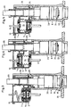
- FIG 1 shows the actuator 10, which like evidently forms a unit that is based on what is known per se Drain valve 6 attached, preferably snapped on is.
- the drain valve 6 is according to Figure 3 at the bottom of a Cistern 35 attached and has a float 33, in which a tubular valve body 20 is mounted. At the bottom At the end of the valve body 20 there is a valve disk 34, which rests tightly on a valve seat 37. to Triggering of a flush is the valve body 20 upwards raised.
- the unit 10 is equipped with a Guide housing 3 provided on the housing 18 of the drain valve 6 is supported.
- this guide housing 3 there are two pneumatic jacks 1 and 2, each are provided with a pneumatic membrane 7 or 8. These are formed as bellows membranes 7 and 8 each with a connecting line 16 or 17 with a pneumatic encoder 32 or 31 connected, as in FIG. 2 schematically shows.
- the connecting line 17 is connected to the encoder 31 and the connecting line 16 connected to the encoder 32.
- These two sensors 31 and 32 are in a housing 30 housed in which a small button 28 and a large one Key 29 are stored. If the key 28 in FIG.
- the lifter 1 is provided with a further driver 4, which is parked on the other driver 5 in the rest position is.
- the driver 4 has a continuous opening 19 in which the valve body 20 is inserted from below is.
- a circumferential projecting edge 20a of the valve body 20 is gripped by a latch 21.
- the locking lug 21 can be deflected radially.
- the unit 10 can therefore when mounting be placed on top of the valve body 20, then the edge 20a automatically engages with the nose 21.
- the Driver 4 is connected to a connecting part 12, wherein an edge 11 of the membrane 7 between these parts 4 and 12 is tightly clamped.
- the membrane 8 is sealed in a similar manner.
- the two connecting parts 12 and 13 are each with a connection means 23 or 24 for the connection the lines 16 and 17 provided.
- FIG 3 is the actuating device 10 in the rest position and so that the drain valve 6 is closed.
- the cistern 35 is filled with rinsing water and ready for rinsing.
- the small button is pressed 28 moved down in Figure 2. This will raise the lifter 2 filled with air and the driver 4 and also the driver 5 raised. Since both carriers 4 and 5 are thus raised the additional weight 26 and the valve body 20 moved up by the corresponding stroke.
- the Figure 4 shows the actuator 10 and the drain valve 6 after triggering a partial rinse.
- the lever 25 is pivoted inwards and lies on the shoulder 36 on.
- the valve plate 34 is from the valve seat 37 lifted off and the rinse water can by not shown here side windows of the housing 18 from the cistern 35 flow out.
- the raised valve body 20 is through additionally loaded the weight body 26. This has to Consequence that the valve body 20 before the complete Emptying the cistern 35 down into the closed position falls.
- the drain valve 6 thus closes after Emptying a predetermined subset.
- This subset is, for example, 6 liters.
- After each actuation of the Key 28 is thus a partial rinse with a predetermined Amount of rinse water triggered.
- the lifter 2 When lowering the valve body 20, the lifter 2 returns to that shown in FIG Home position back, with air from the membrane 8th is displaced by the line 17 into the transmitter 31. in this connection the encoder 31 is bent out again and goes into the Figure 2 shown position back.
Landscapes
- Engineering & Computer Science (AREA)
- Health & Medical Sciences (AREA)
- Life Sciences & Earth Sciences (AREA)
- Hydrology & Water Resources (AREA)
- Public Health (AREA)
- Water Supply & Treatment (AREA)
- Mechanical Engineering (AREA)
- Aviation & Aerospace Engineering (AREA)
- Fluid-Driven Valves (AREA)
- Mechanically-Actuated Valves (AREA)
- Sanitary Device For Flush Toilet (AREA)
- Vehicle Waterproofing, Decoration, And Sanitation Devices (AREA)
Claims (14)
- Dispositif d'actionnement d'un clapet d'évacuation (6) d'un réservoir de chasse d'eau de WC, pourvu de deux boutons (28, 29) pour déclencher au choix une chasse totale ou une chasse partielle, et de deux siphons pneumatiques (1, 2), une chasse totale pouvant être déclenchée avec un siphon (1), caractérisé en ce qu'une chasse partielle peut être déclenchée avec l'autre siphon (2).
- Dispositif selon la revendication 1, caractérisé en ce que les deux siphons (1, 2) sont disposés l'un au-dessus de l'autre, le siphon (2) étant soutenu par l'autre siphon (1).
- Dispositif selon la revendication 1 ou 2, caractérisé en ce que les deux siphons (1, 2) sont logés dans un logement de guidage commun (3).
- Dispositif selon l'une quelconque des revendications 1 à 3, caractérisé en ce que deux tenons d'entraínement (4, 5) sont prévus, le siphon (1) déplaçant le tenon (4), et l'autre siphon (2) déplaçant les deux tenons d'entraínement (4, 5).
- Dispositif selon la revendication 4, caractérisé en ce que le tenon d'entraínement (5) est disposé entre les deux siphons (1, 2) et l'autre tenon d'entraínement (4) est disposé sur un tenon d'entraínement supérieur (5).
- Dispositif selon l'une quelconque des revendications 1 à 5, caractérisé en ce que les deux siphons (1, 2) sont assemblés sur une unité pouvant être encliquetée sur le clapet d'évacuation (6).
- Dispositif selon l'une quelconque des revendications 1 à 6, caractérisé en ce que les deux siphons (1, 2) présentent chacun une membrane pneumatique (7, 8), et en ce qu'au moins une membrane (7) présente un bord (11) qui est bloqué en formant un joint d'étanchéité entre le tenon d'entraínement (4) et une partie (12) pouvant de préférence être encliquetée.
- Dispositif selon l'une quelconque des revendications 3 à 7, caractérisé en ce que le siphon (2) présente une partie de raccordement (13) fixée au logement de guidage et l'autre siphon (1) présente une partie de raccordement (12) mobile par rapport au logement de guidage (3).
- Dispositif selon la revendication 8, caractérisé en ce que les deux parties de raccordement (12, 13) forment spatialement une chambre pneumatique et sont reliées à une canalisation de raccordement (16, 17).
- Dispositif selon la revendication 8 ou 9, caractérisé en ce que la partie de raccordement (12) est reliée au tenon d'entraínement (4) et l'autre partie de raccordement (13) est reliée à un logement (3).
- Dispositif selon l'une quelconque des revendications 1 à 10, caractérisé en ce qu'il peut être encliqueté en tant qu'unité (10) sur le logement (18) du clapet d'évacuation (6).
- Dispositif selon l'une quelconque des revendications 1 à 11, caractérisé en ce que le tenon d'entraínement (4) présente une ouverture continue (19) pour recevoir un tube (20) de clapet (6) et en outre, un moyen (21) pour enclencher le tenon d'entraínement (4) sur le tube (20) de clapet (6).
- Dispositif selon l'une quelconque des revendications 1 à 12, caractérisé en ce que les deux siphons (1, 2) sont reliés respectivement à des poires (31, 32) qui sont logées dans un logement commun (30), deux boutons formés différemment (28, 29) étant insérées dans ce logement (30).
- Dispositif selon l'une quelconque des revendications 1 à 13, caractérisé en ce qu'un tenon d'entraínement (5) est relié à une masse supplémentaire (26), et en ce qu'un deuxième tenon d'entraínement (4) est soutenu par ce tenon d'entraínement (5) et ce deuxième tenon d'entraínement (4) est relié de façon active pour soulever le corps de clapet (20).
Applications Claiming Priority (3)
| Application Number | Priority Date | Filing Date | Title |
|---|---|---|---|
| CH164897 | 1997-07-07 | ||
| CH164897 | 1997-07-07 | ||
| CH1648/97 | 1997-07-07 |
Publications (2)
| Publication Number | Publication Date |
|---|---|
| EP0890680A1 EP0890680A1 (fr) | 1999-01-13 |
| EP0890680B1 true EP0890680B1 (fr) | 2003-05-14 |
Family
ID=4215377
Family Applications (1)
| Application Number | Title | Priority Date | Filing Date |
|---|---|---|---|
| EP98810528A Expired - Lifetime EP0890680B1 (fr) | 1997-07-07 | 1998-06-10 | Dispositif pour l'actionnement d'une soupape de vidange d'un réservoir de chasse d'eau |
Country Status (4)
| Country | Link |
|---|---|
| EP (1) | EP0890680B1 (fr) |
| AT (1) | ATE240442T1 (fr) |
| AU (1) | AU736583B2 (fr) |
| DE (2) | DE29808200U1 (fr) |
Cited By (1)
| Publication number | Priority date | Publication date | Assignee | Title |
|---|---|---|---|---|
| WO2025186169A1 (fr) * | 2024-03-05 | 2025-09-12 | Grohe Ag | Dispositif d'actionnement d'un mécanisme de chasse d'eau de toilettes et mécanisme de chasse d'eau pour toilettes |
Families Citing this family (12)
| Publication number | Priority date | Publication date | Assignee | Title |
|---|---|---|---|---|
| ATE242371T1 (de) * | 1997-12-15 | 2003-06-15 | Geberit Technik Ag | Vorrichtung zur pneumatischen betätigung eines spülkastens |
| EP1197607B1 (fr) * | 2000-10-13 | 2004-05-26 | Geberit Technik Ag | Chasse d'eau pour WC |
| DE10113115A1 (de) | 2001-03-16 | 2002-09-19 | Eisenberg Gmbh Sanitaertechnik | Betätigungsvorrichtung für das Ablaufventil eines WC-Spülkastens |
| ITMI20010276U1 (it) * | 2001-05-16 | 2002-11-18 | Valsir Spa | Sistema modulare per l'allestimento di cassette di risciacquamento diapparecchi sanitari con diverse modalita' di funzionamento, e cassetta |
| DE10253890A1 (de) * | 2002-11-18 | 2004-06-03 | Julian Geppert | Spülkastensteuerung |
| ITMI20031325A1 (it) * | 2003-06-27 | 2004-12-28 | Valsir Spa | Dispositivo pneumatico di azionamento del gruppo valvola di scarico di una cassetta di risciacquo. |
| WO2006079233A2 (fr) * | 2005-01-25 | 2006-08-03 | Closomat Ag | Dispositif concu pour actionner le reservoir de chasse d'eau sur un wc equipe d'un reservoir de chasse d'eau encastre |
| CN103883783B (zh) * | 2012-12-21 | 2017-08-04 | 厦门威迪亚科技有限公司 | 一种气动排水阀的气动感应控制装置 |
| PT3467215T (pt) * | 2017-10-05 | 2020-06-17 | Geberit Int Ag | Guarnição de descarga |
| CN110697600B (zh) * | 2019-09-23 | 2020-11-20 | 宝鸡石油机械有限责任公司 | 一种钻井绞车阀箱控制系统 |
| EP4202135B1 (fr) * | 2021-12-22 | 2024-11-20 | Kohler (China) Investment Co. Ltd. | Dispositif de commande de soupape pneumatique |
| CN217150508U (zh) | 2021-12-22 | 2022-08-09 | 科勒(中国)投资有限公司 | 一种气动阀控制装置 |
Family Cites Families (5)
| Publication number | Priority date | Publication date | Assignee | Title |
|---|---|---|---|---|
| CH641225A5 (de) * | 1979-06-05 | 1984-02-15 | Geberit Ag | Pneumatische betaetigungsvorrichtung an einem spuelkasten-ablaufventil. |
| US4809367A (en) * | 1986-08-08 | 1989-03-07 | Partall Systems (Proprietary) Limited | Cistern flushing apparatus |
| DE3729569A1 (de) * | 1987-09-04 | 1989-03-16 | Schwab Sanitaer Plastic Gmbh | Spuelkasten |
| DE29517363U1 (de) | 1995-01-16 | 1995-12-21 | Geberit Technik AG, Jona, St.Gallen | Spüleinrichtung in einem WC-Spülkasten |
| IT1280896B1 (it) * | 1995-08-04 | 1998-02-11 | Plastic Investment Holding S A | Dispositivo pneumatico per l'azionamento di una valvola di scarico di una cassetta di risciacquo per wc |
-
1998
- 1998-05-07 DE DE29808200U patent/DE29808200U1/de not_active Expired - Lifetime
- 1998-06-10 AT AT98810528T patent/ATE240442T1/de active
- 1998-06-10 DE DE59808327T patent/DE59808327D1/de not_active Expired - Lifetime
- 1998-06-10 EP EP98810528A patent/EP0890680B1/fr not_active Expired - Lifetime
- 1998-07-06 AU AU75023/98A patent/AU736583B2/en not_active Ceased
Cited By (1)
| Publication number | Priority date | Publication date | Assignee | Title |
|---|---|---|---|---|
| WO2025186169A1 (fr) * | 2024-03-05 | 2025-09-12 | Grohe Ag | Dispositif d'actionnement d'un mécanisme de chasse d'eau de toilettes et mécanisme de chasse d'eau pour toilettes |
Also Published As
| Publication number | Publication date |
|---|---|
| DE59808327D1 (de) | 2003-06-18 |
| AU7502398A (en) | 1999-01-14 |
| DE29808200U1 (de) | 1998-07-23 |
| AU736583B2 (en) | 2001-08-02 |
| ATE240442T1 (de) | 2003-05-15 |
| EP0890680A1 (fr) | 1999-01-13 |
Similar Documents
| Publication | Publication Date | Title |
|---|---|---|
| EP0890680B1 (fr) | Dispositif pour l'actionnement d'une soupape de vidange d'un réservoir de chasse d'eau | |
| EP0722020B1 (fr) | Dispositif de chasse dans un réservoir de chasse d'eau | |
| EP1719844B1 (fr) | Clapet d'écoulement d'un réservoir de chasse d'eau | |
| DE19633178A1 (de) | Steuerung für ein mit Unterdruck betätigbares Absaug- und/oder Wasserventil | |
| DE69719196T2 (de) | Schwimmerventil | |
| DE2520760C3 (de) | Ablaufgarnitur für Spülkästen | |
| EP0312750A2 (fr) | Chasse d'eau sous pression pour water-closets | |
| CH670850A5 (fr) | ||
| EP1672130B1 (fr) | Soupape d'évacuation d'un réservoir de chasse | |
| DE10002308A1 (de) | WC-Spülkasten | |
| EP0001131B1 (fr) | Soupape de commande à triple pression munie d'une valve d'accélération pour frein à air comprimé à action indirecte | |
| EP1010826B1 (fr) | Dispositif d'écoulement pour chasse d'eau | |
| EP0103046B1 (fr) | Soupape d'évacuation d'un réservoir de chasse | |
| DE10232399B4 (de) | Zweistufenschalter | |
| EP2072696B1 (fr) | Dispositif d'actionnement pour chasse d'eau | |
| DE2259555A1 (de) | Wasserstandsbegrenzer oder -regler | |
| EP2716825B1 (fr) | Réservoir de chasse d'eau à actionnement hydraulique | |
| DE3640216A1 (de) | Klosettspuelkasten | |
| EP1460188B1 (fr) | Dispositif de chasse pour un réservoir de chasse d'eau | |
| DE851629C (de) | Abortspuelkasten mit Bodenventil | |
| EP1270829B1 (fr) | Dispositif pour l'actionnement d'une soupape de vidange d'un réservoir de chasse d'eau | |
| EP1795662B1 (fr) | Dispositif pour activer le clapet d'un réservoir de chasse d'eau | |
| DE4417722C2 (de) | Betätigungseinrichtung für eine Ablaufarmatur eines Spülkastens | |
| DE69105268T2 (de) | Druckknopfspülmechanismus mit eintauchbarem Körper. | |
| DE8434369U1 (de) | WC - Spülkasten |
Legal Events
| Date | Code | Title | Description |
|---|---|---|---|
| PUAI | Public reference made under article 153(3) epc to a published international application that has entered the european phase |
Free format text: ORIGINAL CODE: 0009012 |
|
| AK | Designated contracting states |
Kind code of ref document: A1 Designated state(s): AT BE CH DE DK ES FR GB IT LI NL PT SE |
|
| AX | Request for extension of the european patent |
Free format text: AL;LT;LV;MK;RO;SI |
|
| 17P | Request for examination filed |
Effective date: 19990713 |
|
| AKX | Designation fees paid |
Free format text: AT BE CH DE DK ES FR GB IT LI NL PT SE |
|
| GRAH | Despatch of communication of intention to grant a patent |
Free format text: ORIGINAL CODE: EPIDOS IGRA |
|
| GRAH | Despatch of communication of intention to grant a patent |
Free format text: ORIGINAL CODE: EPIDOS IGRA |
|
| GRAA | (expected) grant |
Free format text: ORIGINAL CODE: 0009210 |
|
| AK | Designated contracting states |
Designated state(s): AT BE CH DE DK ES FR GB IT LI NL PT SE |
|
| REG | Reference to a national code |
Ref country code: GB Ref legal event code: FG4D Free format text: NOT ENGLISH |
|
| REG | Reference to a national code |
Ref country code: CH Ref legal event code: NV Representative=s name: ISLER & PEDRAZZINI AG Ref country code: CH Ref legal event code: EP |
|
| GBT | Gb: translation of ep patent filed (gb section 77(6)(a)/1977) |
Effective date: 20030515 |
|
| REF | Corresponds to: |
Ref document number: 59808327 Country of ref document: DE Date of ref document: 20030618 Kind code of ref document: P |
|
| PG25 | Lapsed in a contracting state [announced via postgrant information from national office to epo] |
Ref country code: SE Free format text: LAPSE BECAUSE OF FAILURE TO SUBMIT A TRANSLATION OF THE DESCRIPTION OR TO PAY THE FEE WITHIN THE PRESCRIBED TIME-LIMIT Effective date: 20030814 Ref country code: PT Free format text: LAPSE BECAUSE OF FAILURE TO SUBMIT A TRANSLATION OF THE DESCRIPTION OR TO PAY THE FEE WITHIN THE PRESCRIBED TIME-LIMIT Effective date: 20030814 Ref country code: DK Free format text: LAPSE BECAUSE OF FAILURE TO SUBMIT A TRANSLATION OF THE DESCRIPTION OR TO PAY THE FEE WITHIN THE PRESCRIBED TIME-LIMIT Effective date: 20030814 |
|
| PG25 | Lapsed in a contracting state [announced via postgrant information from national office to epo] |
Ref country code: ES Free format text: LAPSE BECAUSE OF FAILURE TO SUBMIT A TRANSLATION OF THE DESCRIPTION OR TO PAY THE FEE WITHIN THE PRESCRIBED TIME-LIMIT Effective date: 20030825 |
|
| ET | Fr: translation filed | ||
| PLBE | No opposition filed within time limit |
Free format text: ORIGINAL CODE: 0009261 |
|
| STAA | Information on the status of an ep patent application or granted ep patent |
Free format text: STATUS: NO OPPOSITION FILED WITHIN TIME LIMIT |
|
| 26N | No opposition filed |
Effective date: 20040217 |
|
| REG | Reference to a national code |
Ref country code: CH Ref legal event code: PCAR Free format text: ISLER & PEDRAZZINI AG;POSTFACH 1772;8027 ZUERICH (CH) |
|
| REG | Reference to a national code |
Ref country code: GB Ref legal event code: 732E Free format text: REGISTERED BETWEEN 20100121 AND 20100127 |
|
| REG | Reference to a national code |
Ref country code: CH Ref legal event code: PUE Owner name: GEBERIT INTERNATIONAL AG Free format text: GEBERIT TECHNIK AG#SCHACHENSTRASSE 77#8645 JONA (CH) -TRANSFER TO- GEBERIT INTERNATIONAL AG#SCHACHENSTRASSE 77#8645 JONA (CH) |
|
| REG | Reference to a national code |
Ref country code: NL Ref legal event code: SD Effective date: 20100304 |
|
| REG | Reference to a national code |
Ref country code: FR Ref legal event code: TP |
|
| PGFP | Annual fee paid to national office [announced via postgrant information from national office to epo] |
Ref country code: NL Payment date: 20120626 Year of fee payment: 15 Ref country code: CH Payment date: 20120622 Year of fee payment: 15 |
|
| PGFP | Annual fee paid to national office [announced via postgrant information from national office to epo] |
Ref country code: BE Payment date: 20120621 Year of fee payment: 15 |
|
| PGFP | Annual fee paid to national office [announced via postgrant information from national office to epo] |
Ref country code: AT Payment date: 20120613 Year of fee payment: 15 |
|
| REG | Reference to a national code |
Ref country code: DE Ref legal event code: R082 Ref document number: 59808327 Country of ref document: DE Representative=s name: HOEGER, STELLRECHT & PARTNER PATENTANWAELTE MB, DE Ref country code: DE Ref legal event code: R082 Ref document number: 59808327 Country of ref document: DE Representative=s name: HOEGER, STELLRECHT & PARTNER PATENTANWAELTE, DE |
|
| BERE | Be: lapsed |
Owner name: GEBERIT INTERNATIONAL A.G. Effective date: 20130630 |
|
| REG | Reference to a national code |
Ref country code: NL Ref legal event code: V1 Effective date: 20140101 |
|
| REG | Reference to a national code |
Ref country code: CH Ref legal event code: PL |
|
| REG | Reference to a national code |
Ref country code: AT Ref legal event code: MM01 Ref document number: 240442 Country of ref document: AT Kind code of ref document: T Effective date: 20130610 |
|
| PG25 | Lapsed in a contracting state [announced via postgrant information from national office to epo] |
Ref country code: BE Free format text: LAPSE BECAUSE OF NON-PAYMENT OF DUE FEES Effective date: 20130630 |
|
| PG25 | Lapsed in a contracting state [announced via postgrant information from national office to epo] |
Ref country code: LI Free format text: LAPSE BECAUSE OF NON-PAYMENT OF DUE FEES Effective date: 20130630 Ref country code: NL Free format text: LAPSE BECAUSE OF NON-PAYMENT OF DUE FEES Effective date: 20140101 Ref country code: CH Free format text: LAPSE BECAUSE OF NON-PAYMENT OF DUE FEES Effective date: 20130630 |
|
| PG25 | Lapsed in a contracting state [announced via postgrant information from national office to epo] |
Ref country code: AT Free format text: LAPSE BECAUSE OF NON-PAYMENT OF DUE FEES Effective date: 20130610 |
|
| PGFP | Annual fee paid to national office [announced via postgrant information from national office to epo] |
Ref country code: GB Payment date: 20140618 Year of fee payment: 17 |
|
| PGFP | Annual fee paid to national office [announced via postgrant information from national office to epo] |
Ref country code: DE Payment date: 20140619 Year of fee payment: 17 |
|
| PGFP | Annual fee paid to national office [announced via postgrant information from national office to epo] |
Ref country code: FR Payment date: 20140619 Year of fee payment: 17 |
|
| PGFP | Annual fee paid to national office [announced via postgrant information from national office to epo] |
Ref country code: IT Payment date: 20140630 Year of fee payment: 17 |
|
| REG | Reference to a national code |
Ref country code: DE Ref legal event code: R082 Ref document number: 59808327 Country of ref document: DE Representative=s name: HOEGER, STELLRECHT & PARTNER PATENTANWAELTE MB, DE |
|
| REG | Reference to a national code |
Ref country code: DE Ref legal event code: R119 Ref document number: 59808327 Country of ref document: DE |
|
| PG25 | Lapsed in a contracting state [announced via postgrant information from national office to epo] |
Ref country code: IT Free format text: LAPSE BECAUSE OF NON-PAYMENT OF DUE FEES Effective date: 20150610 |
|
| GBPC | Gb: european patent ceased through non-payment of renewal fee |
Effective date: 20150610 |
|
| REG | Reference to a national code |
Ref country code: FR Ref legal event code: ST Effective date: 20160229 |
|
| PG25 | Lapsed in a contracting state [announced via postgrant information from national office to epo] |
Ref country code: DE Free format text: LAPSE BECAUSE OF NON-PAYMENT OF DUE FEES Effective date: 20160101 Ref country code: GB Free format text: LAPSE BECAUSE OF NON-PAYMENT OF DUE FEES Effective date: 20150610 |
|
| PG25 | Lapsed in a contracting state [announced via postgrant information from national office to epo] |
Ref country code: FR Free format text: LAPSE BECAUSE OF NON-PAYMENT OF DUE FEES Effective date: 20150630 |