EP0890689B1 - Structure porteuse, en particulier pour revêtement de sol pour surface intérieures ou pavement pour surfaces extérieures - Google Patents
Structure porteuse, en particulier pour revêtement de sol pour surface intérieures ou pavement pour surfaces extérieures Download PDFInfo
- Publication number
- EP0890689B1 EP0890689B1 EP98101167A EP98101167A EP0890689B1 EP 0890689 B1 EP0890689 B1 EP 0890689B1 EP 98101167 A EP98101167 A EP 98101167A EP 98101167 A EP98101167 A EP 98101167A EP 0890689 B1 EP0890689 B1 EP 0890689B1
- Authority
- EP
- European Patent Office
- Prior art keywords
- structure according
- bodies
- constituted
- load
- holes
- Prior art date
- Legal status (The legal status is an assumption and is not a legal conclusion. Google has not performed a legal analysis and makes no representation as to the accuracy of the status listed.)
- Expired - Lifetime
Links
- 238000009408 flooring Methods 0.000 title description 11
- 230000008878 coupling Effects 0.000 claims description 9
- 238000010168 coupling process Methods 0.000 claims description 9
- 238000005859 coupling reaction Methods 0.000 claims description 9
- 239000000463 material Substances 0.000 claims description 6
- 230000004913 activation Effects 0.000 claims description 3
- 238000005192 partition Methods 0.000 claims description 3
- 230000037431 insertion Effects 0.000 claims 1
- 238000003780 insertion Methods 0.000 claims 1
- XLYOFNOQVPJJNP-UHFFFAOYSA-N water Substances O XLYOFNOQVPJJNP-UHFFFAOYSA-N 0.000 description 3
- 238000005266 casting Methods 0.000 description 2
- 239000004568 cement Substances 0.000 description 2
- 238000010276 construction Methods 0.000 description 2
- 230000009467 reduction Effects 0.000 description 2
- 230000001413 cellular effect Effects 0.000 description 1
- 238000009434 installation Methods 0.000 description 1
- 230000000670 limiting effect Effects 0.000 description 1
- 238000004519 manufacturing process Methods 0.000 description 1
- 238000000034 method Methods 0.000 description 1
- 230000004048 modification Effects 0.000 description 1
- 238000012986 modification Methods 0.000 description 1
- 239000004576 sand Substances 0.000 description 1
- 239000007787 solid Substances 0.000 description 1
- 239000013585 weight reducing agent Substances 0.000 description 1
- 239000002023 wood Substances 0.000 description 1
Images



Classifications
-
- E—FIXED CONSTRUCTIONS
- E04—BUILDING
- E04F—FINISHING WORK ON BUILDINGS, e.g. STAIRS, FLOORS
- E04F15/00—Flooring
- E04F15/02—Flooring or floor layers composed of a number of similar elements
- E04F15/02177—Floor elements for use at a specific location
- E04F15/02183—Floor elements for use at a specific location for outdoor use, e.g. in decks, patios, terraces, verandas or the like
-
- E—FIXED CONSTRUCTIONS
- E01—CONSTRUCTION OF ROADS, RAILWAYS, OR BRIDGES
- E01C—CONSTRUCTION OF, OR SURFACES FOR, ROADS, SPORTS GROUNDS, OR THE LIKE; MACHINES OR AUXILIARY TOOLS FOR CONSTRUCTION OR REPAIR
- E01C5/00—Pavings made of prefabricated single units
- E01C5/20—Pavings made of prefabricated single units made of units of plastics, e.g. concrete with plastics, linoleum
-
- E—FIXED CONSTRUCTIONS
- E04—BUILDING
- E04F—FINISHING WORK ON BUILDINGS, e.g. STAIRS, FLOORS
- E04F15/00—Flooring
- E04F15/02—Flooring or floor layers composed of a number of similar elements
- E04F15/024—Sectional false floors, e.g. computer floors
- E04F15/02447—Supporting structures
- E04F15/02464—Height adjustable elements for supporting the panels or a panel-supporting framework
- E04F15/0247—Screw jacks
- E04F15/02476—Screw jacks height-adjustable from the upper side of the floor
-
- E—FIXED CONSTRUCTIONS
- E04—BUILDING
- E04F—FINISHING WORK ON BUILDINGS, e.g. STAIRS, FLOORS
- E04F15/00—Flooring
- E04F15/02—Flooring or floor layers composed of a number of similar elements
- E04F15/02044—Separate elements for fastening to an underlayer
- E04F2015/02105—Separate elements for fastening to an underlayer without load-supporting elongated furring elements between the flooring elements and the underlayer
- E04F2015/02127—Separate elements for fastening to an underlayer without load-supporting elongated furring elements between the flooring elements and the underlayer adjustable perpendicular to the underlayer
Definitions
- the present invention relates to a load-bearing structure particularly for indoor flooring or outdoor paving.
- This known method therefore requires the preliminary study of the water and electric system and the laying of all the associated ducting at a solid base prepared beforehand; said ducts must then be embedded for example by a casting of cement-like material.
- the flooring cannot be laid immediately because said casting must be able to dry appropriately.
- said paving is usually built by using thin cement or inert slabs laid over sand or cement and this requires a long time and entails high costs; these components are also heavy and therefore require suitable tools or means to transport them.
- An example of a panel unit for use in double floors and which allows installation of wiring is known from the document EP-A-0 506 499 A1.
- the aim of the present invention is to solve the above technical problems, eliminating the drawbacks of the cited prior art and thus providing an invention which allows to lay indoor flooring or outdoor paving quickly and easily.
- an important object is to provide an invention in which said laying can occur even without a preliminary laying of water and electric ducting, of course with the option of subsequently laying said ducting quickly and easily.
- Another important object is to provide an invention that allows to obtain an indoor flooring or outdoor paving which is stable over time and safe in use.
- Another important object is to provide an invention which is structurally simple and easy to industrialize.
- Another object is to provide an invention which has low manufacturing costs and allows to produce indoor flooring or outdoor paving at an overall cost which is lower than in the cited prior art.
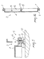
- 1 designates a load-bearing structure for supporting panels or coverings, designated by the reference numeral 2, or for outdoor pavings.
- Said load-bearing structure is constituted by a plurality of modular and load-bearing bodies 3 for supporting the panels or coverings 2 for indoor and outdoor use.
- Said body 3 can be formed for example by using recycled and recyclable material for cost containment.
- Each body 3 is provided with a flat upper surface 4 and, at the corners 5, with a recess or depression 6 whereat first through holes 7 are formed at right angles.
- Means for leveling said body can be arranged within said first holes 7 and can be activated from the upper surface 4 thereof; said means are constituted by a suitable screw 8 provided with a head 9 which can be arranged on a stable plane 10 and with a threaded stem 11 which can be inserted in a complementarily threaded seat formed at said first holes 7.
- Activation of the screw 9 from the upper surface 4 of the body 3 is allowed because at the end of the stem 11 there is provided a seat 12, for example for an Allen screw, or a slot for inserting a complementarily shaped screwdriver or other tool.
- each body 3 there are also provided second through holes 13, which are proximate to the outer perimetric edge 14 and approximately at the center of each body.
- each body 3 is provided with partitions 15 which form a grid-like structure and have a shape forming, in a downward region, a plurality of connected compartments 16 whereat it is possible to pass ducting which is not shown in the figures.
- the load-bearing structure 1 comprises means for the removable mutual locking of a plurality of bodies 3 or of panels or coverings 2 arranged side by side; said means can be activated from the upper surface 4 of each body 3.
- Said removable locking means are constituted by a suitable coupling 17 which can be positioned at, and is shaped complementarily to, a suitable seat which is formed by arranging side by side a plurality of bodies 3 at a corner 5; said seat is formed by the presence of the mutually adjacent recesses or depressions 6.
- the coupling 17 is thus constituted by a plate 18 which is provided, in a downward region, with four bridges 19 located at the corners and arranged along the diagonals; said bridges are essentially shaped like an inverted U, the wings 20a, 20b whereof can be arranged at complementarily shaped guides 21 formed on the portion of the body 3 whereon the first through holes 7 are located; said guides 21 are parallel to the laterally adjacent outer perimetric edge 14 of the body 3 and merge at a region adjacent to the corner 5.
- tabs 22 arranged in a cross-like configuration protrude above the plate 18; their function is to allow, as shown in figure 11, to position and lock between two of said tabs the corresponding sides of a panel or of a covering 2.
- the height of the tabs 22 is such that they can protrude, once the coupling 17 has been inserted, beyond the upper surface 4 of the body 3, by an extent which is equal to the thickness of the panel or covering 2.
- the coupling 17 is similar to the one shown in figure 7 as regards the presence of the plate 18 and of the bridges 19, except for the tabs 22.
- the load-bearing structure can be wall-mounted in order to form a ventilated structure.
- a load-bearing structure having been provided which allows to form a surface for obtaining an indoor flooring or outdoor paving and, at the same, an underlying cellular region for the passage of cables and/or ducting and/or radiating panels; furthermore, said structure can be quickly and easily laid as flooring, avoiding and indeed replacing conventional thin slabs and thus providing faster and shorter laying times, saving time as regards the accessibility and/or walkability of the spaces.
- said structure thanks to the particular use of the couplings, allows to inspect at all times and in any point the area underlying the indoor flooring or outdoor paving.
- Said structure also allows to achieve a significant weight reduction, since it is possible to use lower thicknesses for the panel and/or the finishing covering; said reductions can be on the order of one third in the case of wood panels and of approximately four fifths in comparison with panels made of inert material, and this also entails global cost reduction.
- the structure can also be used for outdoor pavings since it is made of materials which are not affected by the weather conditions.
Landscapes
- Engineering & Computer Science (AREA)
- Architecture (AREA)
- Civil Engineering (AREA)
- Structural Engineering (AREA)
- General Engineering & Computer Science (AREA)
- Floor Finish (AREA)
- Road Paving Structures (AREA)
Claims (11)
- Structure porteuse pour supporter des panneaux ou revêtements ou pour utilisation comme pavage extérieur, constituée par une pluralité de corps modulaires (3), chacun étant pourvu de moyens de mise à niveau (8) qui peuvent être activés depuis la surface supérieure (4), ledit corps (3) étant pourvu intérieurement d'une structure de type grillagé (15) avec des compartiments reliés (16) pour les canalisations, chacun desdits corps ayant des coins, la structure porteuse comprenant en outre des moyens (17) pour le blocage amovible d'une pluralité de corps (3) et/ou de panneaux (2) placés côte à côte, lesdits moyens de blocage (17) pouvant être actionnés depuis la surface supérieure (4) desdits corps (3), et étant constitués d'un accouplement adéquat, ledit accouplement (17) étant constitué d'une plaque (18), caractérisée en ce que ladite plaque a, dans une partie inférieure et aux coins, quatre ponts (19) qui sont placés le long de ses diagonales et qui sont essentiellement de la forme d'un U renversé, dont les ailes (20a-20b) sont adaptables à des guidages de formes complémentaires (21) formés sur une portion du coin (5) de chacun desdits corps (3) sur lequel des premiers trous traversants (7) sont prévus, lesdits guidages (21) étant parallèles au bord du périmètre latéralement adjacent dudit corps (3) et se rejoignant dans une partie qui est adjacente au coin (5).
- Structure, selon la revendication 1, caractérisée en ce que ledit corps (3) est de préférence formé en utilisant du matériau recyclé et recyclable, et comprend une surface supérieure plane (4) et, aux coins (5), un creux ou une dépression (6) où lesdits premiers trous traversants (7) sont formés à angles droits.
- Structure selon les revendications 1 et 2, caractérisée en ce que des moyens (8) de mise à niveau dudit corps (3) peuvent être disposés à l'intérieur desdits premiers trous (7) et peuvent être activés depuis ladite surface supérieure (4) desdits moyens de mise à niveau, lesdits moyens de mise à niveau étant constitués par une vis adaptée (8) munie d'une tête (5) qui peut être appliquée sur un plan stable et d'une tige filetée (11) qui peut être insérée dans un logement fileté complémentairement formé dans lesdits premiers trous (7).
- Structure selon les revendications 1 et 3, caractérisée en ce qu'elle comprend en outre un logement (12) situé à l'extrémité de ladite tige filetée (11), par exemple un logement pour une vis Allen ou une fente pour l'insertion d'un tournevis à forme complémentaire ou d'un autre outil, pour l'activation de ladite vis (8) depuis ladite surface supérieure (4) dudit corps (3).
- Structure selon les revendications 1 et 4, caractérisée en ce que sur chacun desdits corps (3), on a également prévu des seconds trous traversants (13), qui sont à proximité du bord extérieur périmétrique et, substantiellement, au centre de chaque corps (3).
- Structure selon les revendications 1 et 5, caractérisée en ce qu'en dessous de ladite surface supérieure (4) de chacun desdits corps (3) sont formées des divisions (15) formant une structure de type grillagé, lesdites divisions (15) ayant une configuration formant, dans une partie inférieure, une pluralité de compartiments (16) reliés dans lesquels on peut passer les canalisations.
- Structure selon les revendications 1 et 6, caractérisée en ce que ladite structure porteuse (1) comprend lesdits moyens de blocage (17) pour le blocage mutuel amovible d'une pluralité de corps (3) ou de panneaux ou de couvertures (2) placés côte à côte, lesdits moyens de blocage (17) permettant une activation depuis ladite surface supérieure (4) de chacun desdits corps (3) et étant constitués par ladite plaque (18) qui peut être placée, et est de forme complémentaire à un logement qui est formé par lesdits creux ou dépressions (6) mutuellement adjacents en plaçant côte à côte une pluralité de corps (3) à un desdits coins (5).
- Structure selon les revendications 1 et 7, caractérisée en ce qu'elle comprend en outre quatre taquets (22) placés selon une configuration en croix qui dépassent au-dessus de ladite plaque (18) sur le côté opposé par rapport auxdits ponts (19), encore auxdits coins et le long des diagonales de la plaque (18), pour permettre de positionner et de bloquer, entre deux desdits taquets (22), les côtés correspondants d'un desdits panneaux ou couvertures (2).
- Structure selon les revendications 1 et 8, caractérisée en ce que lesdits taquets (22) ont une hauteur suffisante pour dépasser, une fois que ledit accouplement (17) a été inséré, au-delà de ladite surface supérieure (4) dudit corps (3), selon une amplitude qui est égale à l'épaisseur dudit panneau ou couverture (2).
- Structure selon l'une quelconque des revendications 1 à 7 caractérisée en ce que ledit accouplement (17) est constitué par ladite plaque (18) et par lesdits ponts (19) et a une surface plane pour poser du carrelage ou de la moquette ou du parquet, pour un usage extérieur ou pour permettre de poser du carrelage, de la moquette ou du parquet.
- Structure selon une ou plusieurs des revendications précédentes, caractérisée en ce qu'elle est montée en parois de telle sorte que ladite structure de type grillagé (15) réalise une structure ventilée.
Applications Claiming Priority (2)
| Application Number | Priority Date | Filing Date | Title |
|---|---|---|---|
| IT97TV000091A IT1294140B1 (it) | 1997-07-11 | 1997-07-11 | Struttura portante,particolarmente per pavimentazioni da interno o da esterno |
| ITTV970091 | 1997-07-11 |
Publications (3)
| Publication Number | Publication Date |
|---|---|
| EP0890689A2 EP0890689A2 (fr) | 1999-01-13 |
| EP0890689A3 EP0890689A3 (fr) | 1999-06-09 |
| EP0890689B1 true EP0890689B1 (fr) | 2003-04-23 |
Family
ID=11420203
Family Applications (1)
| Application Number | Title | Priority Date | Filing Date |
|---|---|---|---|
| EP98101167A Expired - Lifetime EP0890689B1 (fr) | 1997-07-11 | 1998-01-23 | Structure porteuse, en particulier pour revêtement de sol pour surface intérieures ou pavement pour surfaces extérieures |
Country Status (4)
| Country | Link |
|---|---|
| EP (1) | EP0890689B1 (fr) |
| AT (1) | ATE238468T1 (fr) |
| DE (1) | DE69813683T2 (fr) |
| IT (1) | IT1294140B1 (fr) |
Families Citing this family (2)
| Publication number | Priority date | Publication date | Assignee | Title |
|---|---|---|---|---|
| US12595658B2 (en) * | 2013-10-25 | 2026-04-07 | Mbrico, Llc | Tile and support structure for vertical mounting tiles |
| CN111877685B (zh) * | 2020-08-19 | 2024-12-24 | 安徽山水空间装饰有限责任公司 | 地板铺装龙骨及其施工方法 |
Family Cites Families (5)
| Publication number | Priority date | Publication date | Assignee | Title |
|---|---|---|---|---|
| GB2101174A (en) * | 1981-06-17 | 1983-01-12 | Derwent Plastics Limited | Paving systems |
| US4546580A (en) * | 1983-07-12 | 1985-10-15 | Bridgestone Tire Co., Ltd. | Heat insulation structure for rooftops of buildings |
| JP2528502Y2 (ja) * | 1990-03-20 | 1997-03-12 | フクビ化学工業株式会社 | 二重床用パネル |
| KR100200269B1 (ko) * | 1991-03-26 | 1999-06-15 | 야기 쿠마키치 | 이중바닥용 판넬유니트 |
| US5333423A (en) * | 1992-12-23 | 1994-08-02 | Propst Robert L | Floor system |
-
1997
- 1997-07-11 IT IT97TV000091A patent/IT1294140B1/it active IP Right Grant
-
1998
- 1998-01-23 DE DE69813683T patent/DE69813683T2/de not_active Expired - Fee Related
- 1998-01-23 EP EP98101167A patent/EP0890689B1/fr not_active Expired - Lifetime
- 1998-01-23 AT AT98101167T patent/ATE238468T1/de not_active IP Right Cessation
Also Published As
| Publication number | Publication date |
|---|---|
| DE69813683T2 (de) | 2004-02-26 |
| ATE238468T1 (de) | 2003-05-15 |
| DE69813683D1 (de) | 2003-05-28 |
| IT1294140B1 (it) | 1999-03-22 |
| EP0890689A3 (fr) | 1999-06-09 |
| EP0890689A2 (fr) | 1999-01-13 |
| ITTV970091A1 (it) | 1999-01-11 |
Similar Documents
| Publication | Publication Date | Title |
|---|---|---|
| US6918215B2 (en) | Free floating sub-floor panel | |
| US6941715B2 (en) | Prefabricated modular building component | |
| US5205091A (en) | Modular-accessible-units and method of making same | |
| US4682453A (en) | Floor construction suitable for installation in rooms containing switchgear, computers, and like electrical apparatus, and a method for producing such a floor construction | |
| CA2248289C (fr) | Structure de sol composite | |
| AU2001270298A1 (en) | Prefabricated modular building component | |
| EP0263583A2 (fr) | Plancher d'accès | |
| US20150007508A1 (en) | Insulation element and a system comprising the insulation element | |
| US4698945A (en) | Panel assembly and a method of installing same | |
| GB2057529A (en) | Building panels and building constructions | |
| US20060025512A1 (en) | Prefabricated modular building component and method of use | |
| GB2164073A (en) | Flooring system | |
| CN115807519B (zh) | 一种可拆卸装配式地面安装调节系统及其装配方法 | |
| US20110203200A1 (en) | Deck system | |
| EP0890689A2 (fr) | Structure porteuse, en particulier pour revêtement de sol pour surface intérieures ou pavement pour surfaces extérieures | |
| AU577038B2 (en) | A panel assembly | |
| CN215368112U (zh) | 一种带有可调节支撑的预制板 | |
| US20050000178A1 (en) | Poured-in-place concrete construction components and method of construction | |
| AU2001276229B2 (en) | Free floating sub-floor panel | |
| EP0111763A1 (fr) | Carreau de céramique, carreau de céramique modulaire | |
| JP3051850B2 (ja) | 地中の蓄熱を利用した床の構築方法及び床下地均し治具 | |
| EP1577460A2 (fr) | Système de cale d'espacement rembourrée pour carreaux | |
| CN218643761U (zh) | 一种架空地板 | |
| AU2001276229A1 (en) | Free floating sub-floor panel | |
| US10190322B2 (en) | Interlocking arch tile |
Legal Events
| Date | Code | Title | Description |
|---|---|---|---|
| PUAI | Public reference made under article 153(3) epc to a published international application that has entered the european phase |
Free format text: ORIGINAL CODE: 0009012 |
|
| AK | Designated contracting states |
Kind code of ref document: A2 Designated state(s): AT BE CH DE ES FR GB GR IE IT LI NL SE |
|
| AX | Request for extension of the european patent |
Free format text: AL;LT;LV;MK;RO;SI |
|
| PUAL | Search report despatched |
Free format text: ORIGINAL CODE: 0009013 |
|
| AK | Designated contracting states |
Kind code of ref document: A3 Designated state(s): AT BE CH DE DK ES FI FR GB GR IE IT LI LU MC NL PT SE |
|
| AX | Request for extension of the european patent |
Free format text: AL;LT;LV;MK;RO;SI |
|
| 17P | Request for examination filed |
Effective date: 19991201 |
|
| AKX | Designation fees paid |
Free format text: AT BE CH DE ES FR GB GR IE IT LI NL SE |
|
| 17Q | First examination report despatched |
Effective date: 20011218 |
|
| GRAH | Despatch of communication of intention to grant a patent |
Free format text: ORIGINAL CODE: EPIDOS IGRA |
|
| GRAH | Despatch of communication of intention to grant a patent |
Free format text: ORIGINAL CODE: EPIDOS IGRA |
|
| GRAA | (expected) grant |
Free format text: ORIGINAL CODE: 0009210 |
|
| AK | Designated contracting states |
Designated state(s): AT BE CH DE ES FR GB GR IE IT LI NL SE |
|
| PG25 | Lapsed in a contracting state [announced via postgrant information from national office to epo] |
Ref country code: NL Free format text: LAPSE BECAUSE OF FAILURE TO SUBMIT A TRANSLATION OF THE DESCRIPTION OR TO PAY THE FEE WITHIN THE PRESCRIBED TIME-LIMIT Effective date: 20030423 Ref country code: LI Free format text: LAPSE BECAUSE OF FAILURE TO SUBMIT A TRANSLATION OF THE DESCRIPTION OR TO PAY THE FEE WITHIN THE PRESCRIBED TIME-LIMIT Effective date: 20030423 Ref country code: CH Free format text: LAPSE BECAUSE OF FAILURE TO SUBMIT A TRANSLATION OF THE DESCRIPTION OR TO PAY THE FEE WITHIN THE PRESCRIBED TIME-LIMIT Effective date: 20030423 Ref country code: AT Free format text: LAPSE BECAUSE OF FAILURE TO SUBMIT A TRANSLATION OF THE DESCRIPTION OR TO PAY THE FEE WITHIN THE PRESCRIBED TIME-LIMIT Effective date: 20030423 |
|
| REG | Reference to a national code |
Ref country code: GB Ref legal event code: FG4D |
|
| REG | Reference to a national code |
Ref country code: CH Ref legal event code: EP |
|
| REF | Corresponds to: |
Ref document number: 69813683 Country of ref document: DE Date of ref document: 20030528 Kind code of ref document: P |
|
| REG | Reference to a national code |
Ref country code: IE Ref legal event code: FG4D |
|
| PG25 | Lapsed in a contracting state [announced via postgrant information from national office to epo] |
Ref country code: SE Free format text: LAPSE BECAUSE OF FAILURE TO SUBMIT A TRANSLATION OF THE DESCRIPTION OR TO PAY THE FEE WITHIN THE PRESCRIBED TIME-LIMIT Effective date: 20030723 Ref country code: GR Free format text: LAPSE BECAUSE OF FAILURE TO SUBMIT A TRANSLATION OF THE DESCRIPTION OR TO PAY THE FEE WITHIN THE PRESCRIBED TIME-LIMIT Effective date: 20030723 |
|
| NLV1 | Nl: lapsed or annulled due to failure to fulfill the requirements of art. 29p and 29m of the patents act | ||
| PG25 | Lapsed in a contracting state [announced via postgrant information from national office to epo] |
Ref country code: ES Free format text: LAPSE BECAUSE OF FAILURE TO SUBMIT A TRANSLATION OF THE DESCRIPTION OR TO PAY THE FEE WITHIN THE PRESCRIBED TIME-LIMIT Effective date: 20031030 |
|
| REG | Reference to a national code |
Ref country code: CH Ref legal event code: PL |
|
| ET | Fr: translation filed | ||
| PG25 | Lapsed in a contracting state [announced via postgrant information from national office to epo] |
Ref country code: IE Free format text: LAPSE BECAUSE OF NON-PAYMENT OF DUE FEES Effective date: 20040123 |
|
| PGFP | Annual fee paid to national office [announced via postgrant information from national office to epo] |
Ref country code: GB Payment date: 20040127 Year of fee payment: 7 |
|
| PGFP | Annual fee paid to national office [announced via postgrant information from national office to epo] |
Ref country code: FR Payment date: 20040130 Year of fee payment: 7 |
|
| PG25 | Lapsed in a contracting state [announced via postgrant information from national office to epo] |
Ref country code: BE Free format text: LAPSE BECAUSE OF NON-PAYMENT OF DUE FEES Effective date: 20040131 |
|
| PGFP | Annual fee paid to national office [announced via postgrant information from national office to epo] |
Ref country code: DE Payment date: 20040227 Year of fee payment: 7 |
|
| PLBE | No opposition filed within time limit |
Free format text: ORIGINAL CODE: 0009261 |
|
| STAA | Information on the status of an ep patent application or granted ep patent |
Free format text: STATUS: NO OPPOSITION FILED WITHIN TIME LIMIT |
|
| 26N | No opposition filed |
Effective date: 20040126 |
|
| BERE | Be: lapsed |
Owner name: *SKEMA S.R.L. Effective date: 20040131 |
|
| REG | Reference to a national code |
Ref country code: IE Ref legal event code: MM4A |
|
| PG25 | Lapsed in a contracting state [announced via postgrant information from national office to epo] |
Ref country code: IT Free format text: LAPSE BECAUSE OF NON-PAYMENT OF DUE FEES;WARNING: LAPSES OF ITALIAN PATENTS WITH EFFECTIVE DATE BEFORE 2007 MAY HAVE OCCURRED AT ANY TIME BEFORE 2007. THE CORRECT EFFECTIVE DATE MAY BE DIFFERENT FROM THE ONE RECORDED. Effective date: 20050123 Ref country code: GB Free format text: LAPSE BECAUSE OF NON-PAYMENT OF DUE FEES Effective date: 20050123 |
|
| PG25 | Lapsed in a contracting state [announced via postgrant information from national office to epo] |
Ref country code: DE Free format text: LAPSE BECAUSE OF NON-PAYMENT OF DUE FEES Effective date: 20050802 |
|
| GBPC | Gb: european patent ceased through non-payment of renewal fee |
Effective date: 20050123 |
|
| PG25 | Lapsed in a contracting state [announced via postgrant information from national office to epo] |
Ref country code: FR Free format text: LAPSE BECAUSE OF NON-PAYMENT OF DUE FEES Effective date: 20050930 |
|
| REG | Reference to a national code |
Ref country code: FR Ref legal event code: ST |
|
| PGRI | Patent reinstated in contracting state [announced from national office to epo] |
Ref country code: IT Effective date: 20090401 |
|
| PGFP | Annual fee paid to national office [announced via postgrant information from national office to epo] |
Ref country code: IT Payment date: 20090123 Year of fee payment: 12 |
|
| PG25 | Lapsed in a contracting state [announced via postgrant information from national office to epo] |
Ref country code: IT Free format text: LAPSE BECAUSE OF NON-PAYMENT OF DUE FEES Effective date: 20100123 |