EP0890698B1 - A building facade member and a set of fittings for external mounting in an opening in a building facade and a method of mounting such a facade member - Google Patents
A building facade member and a set of fittings for external mounting in an opening in a building facade and a method of mounting such a facade member Download PDFInfo
- Publication number
- EP0890698B1 EP0890698B1 EP98610022A EP98610022A EP0890698B1 EP 0890698 B1 EP0890698 B1 EP 0890698B1 EP 98610022 A EP98610022 A EP 98610022A EP 98610022 A EP98610022 A EP 98610022A EP 0890698 B1 EP0890698 B1 EP 0890698B1
- Authority
- EP
- European Patent Office
- Prior art keywords
- fitting
- facade
- locking
- wall portion
- opening
- Prior art date
- Legal status (The legal status is an assumption and is not a legal conclusion. Google has not performed a legal analysis and makes no representation as to the accuracy of the status listed.)
- Expired - Lifetime
Links
- 238000000034 method Methods 0.000 title claims description 18
- 238000006073 displacement reaction Methods 0.000 claims description 6
- 238000003780 insertion Methods 0.000 claims description 6
- 230000037431 insertion Effects 0.000 claims description 6
- 230000000717 retained effect Effects 0.000 claims description 5
- 230000003313 weakening effect Effects 0.000 claims description 3
- 238000010276 construction Methods 0.000 description 4
- 230000001419 dependent effect Effects 0.000 description 2
- 238000005553 drilling Methods 0.000 description 2
- 238000009434 installation Methods 0.000 description 2
- 230000035515 penetration Effects 0.000 description 2
- 238000004080 punching Methods 0.000 description 2
- 230000002787 reinforcement Effects 0.000 description 2
- XLYOFNOQVPJJNP-UHFFFAOYSA-N water Substances O XLYOFNOQVPJJNP-UHFFFAOYSA-N 0.000 description 2
- 239000004677 Nylon Substances 0.000 description 1
- 230000000903 blocking effect Effects 0.000 description 1
- 230000000295 complement effect Effects 0.000 description 1
- 230000007797 corrosion Effects 0.000 description 1
- 238000005260 corrosion Methods 0.000 description 1
- 239000000463 material Substances 0.000 description 1
- 230000013011 mating Effects 0.000 description 1
- 239000002184 metal Substances 0.000 description 1
- 238000012986 modification Methods 0.000 description 1
- 230000004048 modification Effects 0.000 description 1
- 238000000465 moulding Methods 0.000 description 1
- 229920001778 nylon Polymers 0.000 description 1
- 230000000149 penetrating effect Effects 0.000 description 1
- 239000004033 plastic Substances 0.000 description 1
- 229920003023 plastic Polymers 0.000 description 1
- 230000000284 resting effect Effects 0.000 description 1
- UQDJGEHQDNVPGU-UHFFFAOYSA-N serine phosphoethanolamine Chemical compound [NH3+]CCOP([O-])(=O)OCC([NH3+])C([O-])=O UQDJGEHQDNVPGU-UHFFFAOYSA-N 0.000 description 1
Images


Classifications
-
- E—FIXED CONSTRUCTIONS
- E06—DOORS, WINDOWS, SHUTTERS, OR ROLLER BLINDS IN GENERAL; LADDERS
- E06B—FIXED OR MOVABLE CLOSURES FOR OPENINGS IN BUILDINGS, VEHICLES, FENCES OR LIKE ENCLOSURES IN GENERAL, e.g. DOORS, WINDOWS, BLINDS, GATES
- E06B1/00—Border constructions of openings in walls, floors, or ceilings; Frames to be rigidly mounted in such openings
- E06B1/56—Fastening frames to the border of openings or to similar contiguous frames
- E06B1/60—Fastening frames to the border of openings or to similar contiguous frames by mechanical means, e.g. anchoring means
- E06B1/6015—Anchoring means
- E06B1/6023—Anchoring means completely hidden between the frame and the border of the opening, at least part of the means being previously fixed to the wall
-
- E—FIXED CONSTRUCTIONS
- E06—DOORS, WINDOWS, SHUTTERS, OR ROLLER BLINDS IN GENERAL; LADDERS
- E06B—FIXED OR MOVABLE CLOSURES FOR OPENINGS IN BUILDINGS, VEHICLES, FENCES OR LIKE ENCLOSURES IN GENERAL, e.g. DOORS, WINDOWS, BLINDS, GATES
- E06B1/00—Border constructions of openings in walls, floors, or ceilings; Frames to be rigidly mounted in such openings
- E06B1/56—Fastening frames to the border of openings or to similar contiguous frames
- E06B1/60—Fastening frames to the border of openings or to similar contiguous frames by mechanical means, e.g. anchoring means
- E06B1/6069—Separate spacer means acting exclusively in the plane of the opening; Shims; Wedges; Tightening of a complete frame inside a wall opening
Definitions
- the present invention relates to a combination of a building facade member having a framework structure, including lower and upper horizontal hollow profiles and vertical hollow profiles for external mounting in an opening in a building facade defined by a substantially horizontal lower spandrel portion and a substantially horizontal upper ceiling portion and a set of mounting fittings for mounting the facade member in the facade opening.
- the object of the invention is in particular external mounting of building facade members of the type known from EP-A-0 474 582 and EP-A-0 687 783.
- a facade member may typically be designed as a framework structure comprising two horizontal and two vertical hollow profiles and adapted for mounting over an opening for a balcony, a door or a window or other types of facade openings in buildings.
- Prior art building facade members have usually been mounted in façade openings by fastening the facade member to the lower spandrel portion and the upper ceiling portion of the opening by means of fittings in the form of mounting angles of L, U or Z shape, or flat bars which engage mating parts of the façade member frame structure and are secured to the spandrel and ceiling portions by screw or bolt connections.
- the facade member When using this way of mounting, the facade member will typically project from the front of the building facade and thus not appear as an integral part thereof.
- the mounting of facade members by this method is furthermore very labour demanding and involves considerable costs, to which may be added that fittings of the above type will not normally be able to compensate for irregularities, if any, in and about the facade opening.
- the facade member is first placed directly resting, possibly with adjustment, on the spandrel portion of an opening in a building facade, following which screw or bolt connections are established by drilling through hollow profiles and adjacent parts of the supporting building structure.
- Such a drilling through the hollow profiles of the facade member entails a risk of moisture and water penetration with subsequent corrosion damage both to the profiles of the facade member and to the building reinforcement, and a weakening of the hollow profiles such that a reinforcement or overdimensioning is required, the result being additional costs.
- the mounting process may be difficult to control in a safe way, since during part of the mounting, until fastening in the facade opening has taken place, the facade member is freely movable relative to the facade opening, ultimately involving the risk that the facade member gets completely out of control and is damaged or lost, which in the latter case entails the risk of damaging other objects or persons.
- a plurality of slotted clip members are disposed each having a flange portion engaging a groove in the sash frame and a closed elongate inclined slot to be engaged at its innermost end by a roll pin, which is inserted in a hole in the rail member in a temporary position of the sash construction with respect to the rail members.
- the invention also relates to a method for mounting a building facade member of the type stated over an opening in a building facade by use of a set of mounting fittings as defined.
- this method is characterized in that after positioning of its lower horizontal hollow profile relative to the first fitting member designed as a profiled rail member the facade member is turned by a tilting movement towards said unlocked position, in which the lower horizontal hollow profile is supported by said profiled rail member, and that at the end of said tilting movement said second and third fitting members are brought into mutual engagement in said engagement position of the third fitting member and locked with respect to each other after displacement of the third fitting member to said locking position.
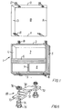
- the building facade member 1 shown in Fig. 1 is manufactured as a framework structure with an upper horizontal hollow profile 2, a lower horizontal hollow profile 3 and vertical side profiles 4 and 5 and moreover comprises, in the embodiment shown, a horizontal middle portion 6, and in the lower one of the window openings 7 and 8 separated by said middle portion a glazing bar portion 9 which like the middle portion 6 may be designed as a hollow profile.
- the facade opening 10 shown in the figure comprises a lower spandrel portion 11 and an upper ceiling portion 21 and is moreover defined by side walls 13 and 14.
- fittings For the mounting of such a building facade member conventional fittings may be used which comprise flat bars 15 and 16 fastened to the spandrel portion 11 of the facade opening and to the lower horizontal hollow profile 3 of the building facade member, respectively, and L-shaped angle-fittings 17 and 18 fastened to the ceiling portion 12 of the facade opening 10 and to the upper horizontal hollow profile 2 of the building facade member 1.
- the fittings designed as flat bars and angle-fittings are brought into abutment against each other and connected with bolt and nut joints.
- the mounting is performed without any kind of safe guiding of the building facade member, and after the fastening by means of said bolt-nut-joints, the building facade member will be displaced and protrude in front of the building facade and so to speak be hanging on the outside thereof, such that subsequently an extensive flashing will be required in order to ensure the necessary tightness against water penetration and wind impact.
- Fig. 2 shows in a simple and schematic design a possible embodiment of a building facade member 19 according to the invention with an upper horizontal hollow profile 21 and a lower horizontal hollow profile 22, which together with side profiles (not shown) encase a pane portion 20 which may be retained in conventionally designed recesses 23 and 24.
- the lower horizontal hollow profile 22 has two wall portions 25 and 26 projecting downwards from the bottom side, of which a first downwards projecting wall portion 25 has a height greater than that of the second downwards projecting wall portion 26, whereas the latter wall portion has an L-shaped cross section providing a foot member 27.
- This design of the profile 22 is intended for positioning and provisionally supporting the building facade member relative to a first fitting member 28 of a set of mounting fittings designed for the mounting of the building facade member 19.
- the member 28 is formed as an elongate profiled rail member which at its top side is provided with an external opening recess 29 for positioning of the first downwards projecting wall portion 25 of the profile 22 and an internal groove 30 for accommodating the second downwards projecting wall portion 26 with the foot member 27.
- the profiled rail member 28 is fastened to the lower spandrel portion 31 of the facade opening by means of screws 32, and with a view to ensuring a horizontal positioning of the member 28, one or more brick-shaped adjusting members 33 of a design e.g. as illustrated in Fig. 4, may be arranged between the profile member and the spandrel portion.
- a second fitting member of the set of mounting fittings is fastened to the upper ceiling portion 34 of the facade opening, said second fitting member having the shape of a screw 35, which is screwed into a bore 36 in the ceiling portion 34.
- the upper horizontal hollow profile 21 of the building facade member is at its upper side provided with projecting, L-shaped wall portions 37 and 38 defining an upwards open groove 39 of a preferably dovetailed cross section.
- a third fitting member in the form of a locking fitting 40 is retained to be longitudinally displaceable, but fixable in the groove 39.
- the locking fitting 40 comprises a substantially horizontal wall portion 41, in which a slot 43 is provided which opens at a side edge 42 of the wall portion 41, the bottom of said groove being displaced relative to the opening thereof in the direction of displacement of the locking fitting 40, which is defined by two substantially T-shaped foot members 44 and 45 corresponding to the cross sectional profile of the dovetailed groove 39.
- the foot members 44 and 45 may at their top side 79 furthermore be provided with fixing means (not shown), for instance small pins or the like, for engagement with the projecting wall portions 37 and 38 during the process of tightening.
- the slot 43 is substantially L-shaped, such that, when the locking fitting 40 is in an engagement position, it may get into engagement with the screw 35 mounted in the ceiling portion of the facade opening at the end of the tilting movement of the facade member 19, by which the second downwards projecting leg 26 from the lower horizontal profile 21 is brought in supporting abutment against the groove 30 in the profiled rail member 28.
- the locking fitting 40 is displaced in the groove 39 in the direction of the arrow 46 in Fig. 3 to take up a locking position, in which the fitting 40 is retained relative to the screw 35 and fixed when the screw is tightened.
- the method of mounting the facade member shown in fig. 2 in the facade opening shown thus comprises an initial mounting of the profiled rail member 28 and the screw 35 in the spandrel and ceiling portions 31 and 34 of the facade opening and mounting of the longitudinal locking fitting 40 in the groove 39 in the upper horizontal profile of the facade member 19, such that all three fitting members of the set of mounting fittings have been mounted prior to commencing of the handling of the facade member 19.
- the facade member 19 is then positioned relative to the profiled rail member 28 by bringing the first downwards projecting wall portion 25 of the lower horizontal profile 22 in abutment against the exterior recess 29 of the profiled rail member 28.
- the second downwards projecting wall portion 26 with the foot member 27 is now brought into supporting abutment against the bottom of the groove 30 in the profiled rail member 28, and simultaneously the locking fitting 40, which has been mounted in the groove 39 in advance in a suitable engagement position, is brought into engagement with the screw 35, following which the locking fitting 40 is displaced to the locking position and fixed therein by tightening of the screw 35.
- a compensation for irregularities in the facade opening may be performed by an adjustment by means of one or more adjusting members 33 of the design shown in Fig. 4.
- the brick-shaped adjusting member 33 which may be manufactured by moulding or punching from a suitable metal or plastics material, for instance nylon, may be designed as a comparatively flat disc-shaped member with an open recess 47 corresponding to the shaft diameter of the screw or bolt together with which the adjusting member is to be used, and with a projecting catch member 48 facilitating correct insertion of the adjusting member 33.
- the catch member 48 may at the mounting advantageously be turned to be positioned in parallel with the longitudinal direction of the hollow profile 51 or be provided opposite its free end with a weakening line 80 to be broken off after its insertion.
- the desired adjustment may be effected by the use of a suitable number of adjustment members 33.
- the adjusting member 33 may have a wedge-shaped cross section, such that two members which may be provided with engagement means on their surfaces may be pushed together from opposite sides to obtain a controllable adjustment height.
- the balcony facade member 49 shown in Fig. 5 and having a sliding pane portion 50 is provided with an upper horizontal hollow profile 51 and a lower horizontal hollow profile 52 with a design in principle known from EP-A-0 687 783, three canals or grooves 55, 56 and 57 being formed by projecting L-and T-shaped wall portions 53 and 54, respectively, at the upper side of the upper profile 51 and at the bottom side of the lower profile 52, said canals or grooves having preferably a dovetailed cross section.
- the first fitting member of the set of fittings designed as an elongate profiled rail member 58 comprises a substantially plane wall portion 60 for abutment against the spandrel portion 59 of the facade opening, possibly through one or more adjusting members 33, and a wall portion 61 projection upwards therefrom and having a hook-shaped, bent edge portion 62, which may be introduced in the uttermost groove 55 in the bottom side of the lower horizontal profile 52 of the locking member 49.
- edge portion 62 At its free edge the edge portion 62 is provided with a recess 63 serving as abutment for an external, open edge portion 64, which is formed by the L-shaped wall portion 53, for the groove 55.
- the second fitting member of the set of mounting fittings may like in the embodiment in Fig. 2 comprise a screw 67 for mounting in a wall peg in a bore in the ceiling portion 68 of the facade opening.
- the third fitting member designed as a locking fitting may be designed in the same manner as shown in Fig. 3 suited for longitudinal and fixed mounting in the middle groove 56 of the three grooves 55 - 57 at the top side of the upper profile 51 of the facade member 49.
- the locking fitting 69 may in a modification be designed such that at the ends of the substantially horizontal wall portion 70, in which, in this case, a linear, tilting slot 71 is provided, it is provided with staggered end portions 72 and 73 for bolts 74, the heads 75 of which are introduced in the groove 56.
- the fixing of the lock member 69 in the groove 56 may here be performed by tightening of nuts 76 positioned on the opposite side of the end portions 72 and 73, the locking fitting 69 being after engagement with the screw 66 displaced in the groove 56 into the locking position.
- the method for mounting the facade member 49 in Fig. 5 is, as far as the positioning of the lower horizontal profile 52 of the facade member 49 is concerned, substantially identical with the one described above in respect of the embodiment in Fig. 2, such as will be seen from Fig. 7, which describes a) - e) various phases of the mounting process.
- the invention is not limited to the embodiment shown of the hollow profiles and the fitting members, but may within the scope of the appended claims be used in connection with hollow profiles of arbitrary cross sectional profiles.
- the first fitting member of the set of mounting fittings does not necessarily have to be designed as a through-going profiled rail member, though this will normally be preferred.
- the number of the second and third fitting members may be varied according to the size of the actual facade member.
Landscapes
- Engineering & Computer Science (AREA)
- Mechanical Engineering (AREA)
- Civil Engineering (AREA)
- Structural Engineering (AREA)
- Finishing Walls (AREA)
- Door And Window Frames Mounted To Openings (AREA)
- Joining Of Building Structures In Genera (AREA)
- Road Signs Or Road Markings (AREA)
Applications Claiming Priority (2)
| Application Number | Priority Date | Filing Date | Title |
|---|---|---|---|
| DK199700850A DK174316B1 (da) | 1997-07-11 | 1997-07-11 | Lukningselement og montagebeslagsæt til montering i en åbning i en bygningsfacade og fremgangsmåde ved montering af et sådant lukningselement |
| DK85097 | 1997-07-11 |
Publications (3)
| Publication Number | Publication Date |
|---|---|
| EP0890698A2 EP0890698A2 (en) | 1999-01-13 |
| EP0890698A3 EP0890698A3 (en) | 1999-12-01 |
| EP0890698B1 true EP0890698B1 (en) | 2004-06-16 |
Family
ID=8098256
Family Applications (1)
| Application Number | Title | Priority Date | Filing Date |
|---|---|---|---|
| EP98610022A Expired - Lifetime EP0890698B1 (en) | 1997-07-11 | 1998-07-09 | A building facade member and a set of fittings for external mounting in an opening in a building facade and a method of mounting such a facade member |
Country Status (5)
| Country | Link |
|---|---|
| EP (1) | EP0890698B1 (da) |
| AT (1) | ATE269475T1 (da) |
| DE (1) | DE69824489D1 (da) |
| DK (1) | DK174316B1 (da) |
| PL (1) | PL327431A1 (da) |
Cited By (2)
| Publication number | Priority date | Publication date | Assignee | Title |
|---|---|---|---|---|
| DE102010056193A1 (de) | 2010-12-28 | 2012-06-28 | Joh. Sprinz Gmbh & Co. Kg | Schiebefassade |
| WO2026128935A1 (de) * | 2024-12-18 | 2026-06-25 | Julius Blum Gmbh | Verfahren zur montage eines blendelements |
Families Citing this family (3)
| Publication number | Priority date | Publication date | Assignee | Title |
|---|---|---|---|---|
| WO2013137780A1 (ru) * | 2012-03-14 | 2013-09-19 | Andreyanov Sergey Gennadevich | Кронштейн крепежный |
| US11414914B2 (en) * | 2020-07-30 | 2022-08-16 | Champion Trust Llc | Glazed panel installation system and method |
| NL2033464B1 (en) * | 2022-11-04 | 2024-05-24 | Buva Rationele Bouwprodukten B V | Frame for a door and/or window and method for placing the same |
Family Cites Families (13)
| Publication number | Priority date | Publication date | Assignee | Title |
|---|---|---|---|---|
| US2475885A (en) | 1945-06-06 | 1949-07-12 | E K Geyser Company | Window |
| US3503168A (en) * | 1967-11-30 | 1970-03-31 | Budd Co | Window sash construction |
| IT1035892B (it) * | 1974-06-05 | 1979-10-20 | Hulinsky J | Dispositivo e procedimento per il fissaggio di intelaiature di porte e finestre |
| FR2516586A1 (fr) * | 1981-11-19 | 1983-05-20 | Technal France | Procede d'installation d'un chassis de remplacement pour portes, fenetres ou elements analogues sur une huisserie pre-existante, et systeme pour la mise en oeuvre de celui-ci |
| DE3540159C1 (en) * | 1985-11-13 | 1987-01-08 | Hueppe Gmbh | Connecting arrangement for the frame bars of doors and walls of a shower partition |
| FR2607548B3 (fr) * | 1986-11-27 | 1988-12-30 | Materiel Etancheite Batiments | Cale d'entretoisement notamment pour le montage des batis de fenetres et analogues |
| DE3642340A1 (de) * | 1986-12-11 | 1988-06-23 | Franz Brinkmann Gmbh | Kellerfenster in einem massiven rahmen |
| DK171514B1 (da) | 1990-08-30 | 1996-12-16 | Rasmussen Kann Ind As | Altanlukningssystem til brug ved facaderenovering i bestående etagebyggeri |
| GB2255999A (en) * | 1991-05-20 | 1992-11-25 | Glazpart Ltd | Frame spacing plate |
| DE4135126C2 (de) * | 1991-10-24 | 1994-09-22 | Weru Ag | Befestigungsvorrichtung, insbesondere für eine Fenster-Festverglasung |
| DK172261B1 (da) | 1994-06-16 | 1998-02-09 | Rasmussen Kann Ind As | Facadelukningssystem |
| DE9420958U1 (de) * | 1994-12-31 | 1995-03-30 | Rathsack, Wolfgang, 17213 Strietfeld | Vorrichtung zum Höhenausgleich von Bauelementen |
| DE29622611U1 (de) * | 1996-05-24 | 1997-03-06 | Aco Severin Ahlmann Gmbh & Co Kg, 24768 Rendsburg | Einrichtung zum Befestigen eines Fenstereinsatzes |
-
1997
- 1997-07-11 DK DK199700850A patent/DK174316B1/da not_active IP Right Cessation
-
1998
- 1998-07-09 AT AT98610022T patent/ATE269475T1/de not_active IP Right Cessation
- 1998-07-09 EP EP98610022A patent/EP0890698B1/en not_active Expired - Lifetime
- 1998-07-09 DE DE69824489T patent/DE69824489D1/de not_active Expired - Fee Related
- 1998-07-11 PL PL98327431A patent/PL327431A1/xx not_active Application Discontinuation
Cited By (2)
| Publication number | Priority date | Publication date | Assignee | Title |
|---|---|---|---|---|
| DE102010056193A1 (de) | 2010-12-28 | 2012-06-28 | Joh. Sprinz Gmbh & Co. Kg | Schiebefassade |
| WO2026128935A1 (de) * | 2024-12-18 | 2026-06-25 | Julius Blum Gmbh | Verfahren zur montage eines blendelements |
Also Published As
| Publication number | Publication date |
|---|---|
| EP0890698A2 (en) | 1999-01-13 |
| EP0890698A3 (en) | 1999-12-01 |
| DE69824489D1 (de) | 2004-07-22 |
| DK85097A (da) | 1999-01-12 |
| ATE269475T1 (de) | 2004-07-15 |
| PL327431A1 (en) | 1999-01-18 |
| DK174316B1 (da) | 2002-12-02 |
Similar Documents
| Publication | Publication Date | Title |
|---|---|---|
| US7313890B2 (en) | Wall opening support system | |
| CA1326120C (en) | Building enclosure system and method | |
| US3992833A (en) | Apparatus for mounting a window or a door frame | |
| US7168219B2 (en) | Support apparatuses and jambs for windows and doors and methods of constructing same | |
| US4011700A (en) | Adjustable-height post assembly for ready installation on a window frame or the like | |
| GB2246149A (en) | Structural post for wall ties | |
| WO1996005389A1 (en) | Auxiliary surface-forming member for construction elements | |
| CA2330118A1 (en) | Seam clamp | |
| US4714367A (en) | Coupling assembly for joining two profiled rails | |
| FI95955B (fi) | Julkisivusovitelma, joka käsittää kiinnitys- ja säätölaitteen tasomaisten verhouselementtien suuntaamiseksi kolmiulotteisesti | |
| GB2214414A (en) | Improvements relating to shelving | |
| EP0890698A2 (en) | A building facade member and a set of fittings for external mounting in an opening in a building facade and a method of mounting such a facade member | |
| RU2089713C1 (ru) | Система соединения профильных элементов дверей и окон, способ соединения пары профилей и рама дверей и окон | |
| JP2912276B2 (ja) | 鋼製建具の設置方法及びそれに使用する設置金具 | |
| CA2039693A1 (en) | Guide rail system for lifts | |
| EP0011992B1 (en) | A profile system having support members and beams | |
| US20230230512A1 (en) | Display mounting system | |
| EP0491010A1 (en) | METHOD OF JOINING TWO STRUCTURAL ELEMENTS USING AN ADJUSTABLE FASTENING DEVICE, AND CHASSIS USED IN THE SAME. | |
| JP3483699B2 (ja) | 外壁パネルの支持構造 | |
| US3207479A (en) | Railing structure | |
| CZ337292A3 (en) | Method of fixing especially cover boards during their additional joining and a fixing system | |
| US12428841B2 (en) | Balcony developments | |
| US20230167663A1 (en) | Barn door track system and related methods of installation | |
| JP2024080783A (ja) | 非溶接固定構造および非溶接固定方法 | |
| JPS6037931Y2 (ja) | パネル取り付け具 |
Legal Events
| Date | Code | Title | Description |
|---|---|---|---|
| PUAI | Public reference made under article 153(3) epc to a published international application that has entered the european phase |
Free format text: ORIGINAL CODE: 0009012 |
|
| AK | Designated contracting states |
Kind code of ref document: A2 Designated state(s): AT BE CH CY DE DK ES FI FR GB GR IE IT LI LU MC NL PT SE |
|
| AX | Request for extension of the european patent |
Free format text: AL;LT;LV;MK;RO;SI |
|
| PUAL | Search report despatched |
Free format text: ORIGINAL CODE: 0009013 |
|
| AK | Designated contracting states |
Kind code of ref document: A3 Designated state(s): AT BE CH CY DE DK ES FI FR GB GR IE IT LI LU MC NL PT SE |
|
| AX | Request for extension of the european patent |
Free format text: AL;LT;LV;MK;RO;SI |
|
| 17P | Request for examination filed |
Effective date: 19991224 |
|
| AKX | Designation fees paid |
Free format text: AT BE CH CY DE DK ES FI FR GB GR IE IT LI LU MC NL PT SE |
|
| AXX | Extension fees paid |
Free format text: AL PAYMENT 19991224;LT PAYMENT 19991224;LV PAYMENT 19991224;MK PAYMENT 19991224;RO PAYMENT 19991224;SI PAYMENT 19991224 |
|
| RAP1 | Party data changed (applicant data changed or rights of an application transferred) |
Owner name: VKR HOLDING A/S |
|
| RAP1 | Party data changed (applicant data changed or rights of an application transferred) |
Owner name: WINDOOR AB |
|
| 17Q | First examination report despatched |
Effective date: 20030430 |
|
| GRAP | Despatch of communication of intention to grant a patent |
Free format text: ORIGINAL CODE: EPIDOSNIGR1 |
|
| GRAS | Grant fee paid |
Free format text: ORIGINAL CODE: EPIDOSNIGR3 |
|
| GRAA | (expected) grant |
Free format text: ORIGINAL CODE: 0009210 |
|
| AK | Designated contracting states |
Kind code of ref document: B1 Designated state(s): AT BE CH CY DE DK ES FI FR GB GR IE IT LI LU MC NL PT SE |
|
| AX | Request for extension of the european patent |
Extension state: AL LT LV MK RO SI |
|
| PG25 | Lapsed in a contracting state [announced via postgrant information from national office to epo] |
Ref country code: NL Free format text: LAPSE BECAUSE OF FAILURE TO SUBMIT A TRANSLATION OF THE DESCRIPTION OR TO PAY THE FEE WITHIN THE PRESCRIBED TIME-LIMIT Effective date: 20040616 Ref country code: LI Free format text: LAPSE BECAUSE OF FAILURE TO SUBMIT A TRANSLATION OF THE DESCRIPTION OR TO PAY THE FEE WITHIN THE PRESCRIBED TIME-LIMIT Effective date: 20040616 Ref country code: IT Free format text: LAPSE BECAUSE OF FAILURE TO SUBMIT A TRANSLATION OF THE DESCRIPTION OR TO PAY THE FEE WITHIN THE PRESCRIBED TIME-LIMIT;WARNING: LAPSES OF ITALIAN PATENTS WITH EFFECTIVE DATE BEFORE 2007 MAY HAVE OCCURRED AT ANY TIME BEFORE 2007. THE CORRECT EFFECTIVE DATE MAY BE DIFFERENT FROM THE ONE RECORDED. Effective date: 20040616 Ref country code: FR Free format text: LAPSE BECAUSE OF NON-PAYMENT OF DUE FEES Effective date: 20040616 Ref country code: FI Free format text: LAPSE BECAUSE OF FAILURE TO SUBMIT A TRANSLATION OF THE DESCRIPTION OR TO PAY THE FEE WITHIN THE PRESCRIBED TIME-LIMIT Effective date: 20040616 Ref country code: CY Free format text: LAPSE BECAUSE OF FAILURE TO SUBMIT A TRANSLATION OF THE DESCRIPTION OR TO PAY THE FEE WITHIN THE PRESCRIBED TIME-LIMIT Effective date: 20040616 Ref country code: CH Free format text: LAPSE BECAUSE OF FAILURE TO SUBMIT A TRANSLATION OF THE DESCRIPTION OR TO PAY THE FEE WITHIN THE PRESCRIBED TIME-LIMIT Effective date: 20040616 Ref country code: BE Free format text: LAPSE BECAUSE OF FAILURE TO SUBMIT A TRANSLATION OF THE DESCRIPTION OR TO PAY THE FEE WITHIN THE PRESCRIBED TIME-LIMIT Effective date: 20040616 Ref country code: AT Free format text: LAPSE BECAUSE OF FAILURE TO SUBMIT A TRANSLATION OF THE DESCRIPTION OR TO PAY THE FEE WITHIN THE PRESCRIBED TIME-LIMIT Effective date: 20040616 |
|
| REG | Reference to a national code |
Ref country code: GB Ref legal event code: FG4D |
|
| REG | Reference to a national code |
Ref country code: CH Ref legal event code: EP |
|
| PG25 | Lapsed in a contracting state [announced via postgrant information from national office to epo] |
Ref country code: LU Free format text: LAPSE BECAUSE OF NON-PAYMENT OF DUE FEES Effective date: 20040709 Ref country code: IE Free format text: LAPSE BECAUSE OF NON-PAYMENT OF DUE FEES Effective date: 20040709 |
|
| REF | Corresponds to: |
Ref document number: 69824489 Country of ref document: DE Date of ref document: 20040722 Kind code of ref document: P |
|
| REG | Reference to a national code |
Ref country code: IE Ref legal event code: FG4D |
|
| PG25 | Lapsed in a contracting state [announced via postgrant information from national office to epo] |
Ref country code: MC Free format text: LAPSE BECAUSE OF NON-PAYMENT OF DUE FEES Effective date: 20040731 |
|
| PG25 | Lapsed in a contracting state [announced via postgrant information from national office to epo] |
Ref country code: SE Free format text: LAPSE BECAUSE OF FAILURE TO SUBMIT A TRANSLATION OF THE DESCRIPTION OR TO PAY THE FEE WITHIN THE PRESCRIBED TIME-LIMIT Effective date: 20040916 Ref country code: GR Free format text: LAPSE BECAUSE OF FAILURE TO SUBMIT A TRANSLATION OF THE DESCRIPTION OR TO PAY THE FEE WITHIN THE PRESCRIBED TIME-LIMIT Effective date: 20040916 Ref country code: GB Free format text: LAPSE BECAUSE OF NON-PAYMENT OF DUE FEES Effective date: 20040916 Ref country code: DK Free format text: LAPSE BECAUSE OF FAILURE TO SUBMIT A TRANSLATION OF THE DESCRIPTION OR TO PAY THE FEE WITHIN THE PRESCRIBED TIME-LIMIT Effective date: 20040916 |
|
| PG25 | Lapsed in a contracting state [announced via postgrant information from national office to epo] |
Ref country code: ES Free format text: LAPSE BECAUSE OF FAILURE TO SUBMIT A TRANSLATION OF THE DESCRIPTION OR TO PAY THE FEE WITHIN THE PRESCRIBED TIME-LIMIT Effective date: 20040927 |
|
| LTIE | Lt: invalidation of european patent or patent extension |
Effective date: 20040616 |
|
| NLV1 | Nl: lapsed or annulled due to failure to fulfill the requirements of art. 29p and 29m of the patents act | ||
| REG | Reference to a national code |
Ref country code: CH Ref legal event code: PL |
|
| PG25 | Lapsed in a contracting state [announced via postgrant information from national office to epo] |
Ref country code: DE Free format text: LAPSE BECAUSE OF NON-PAYMENT OF DUE FEES Effective date: 20050201 |
|
| REG | Reference to a national code |
Ref country code: IE Ref legal event code: MM4A |
|
| PLBE | No opposition filed within time limit |
Free format text: ORIGINAL CODE: 0009261 |
|
| STAA | Information on the status of an ep patent application or granted ep patent |
Free format text: STATUS: NO OPPOSITION FILED WITHIN TIME LIMIT |
|
| GBPC | Gb: european patent ceased through non-payment of renewal fee |
Effective date: 20040916 |
|
| 26N | No opposition filed |
Effective date: 20050317 |
|
| EN | Fr: translation not filed | ||
| PG25 | Lapsed in a contracting state [announced via postgrant information from national office to epo] |
Ref country code: PT Free format text: LAPSE BECAUSE OF NON-PAYMENT OF DUE FEES Effective date: 20041116 |