EP0890713A2 - Cadre de support pour arbre à cames - Google Patents
Cadre de support pour arbre à cames Download PDFInfo
- Publication number
- EP0890713A2 EP0890713A2 EP98110042A EP98110042A EP0890713A2 EP 0890713 A2 EP0890713 A2 EP 0890713A2 EP 98110042 A EP98110042 A EP 98110042A EP 98110042 A EP98110042 A EP 98110042A EP 0890713 A2 EP0890713 A2 EP 0890713A2
- Authority
- EP
- European Patent Office
- Prior art keywords
- bearing frame
- camshaft bearing
- internal combustion
- combustion engine
- cylinder head
- Prior art date
- Legal status (The legal status is an assumption and is not a legal conclusion. Google has not performed a legal analysis and makes no representation as to the accuracy of the status listed.)
- Granted
Links
- 238000002347 injection Methods 0.000 claims abstract description 26
- 239000007924 injection Substances 0.000 claims abstract description 26
- 239000010687 lubricating oil Substances 0.000 claims abstract description 10
- 239000002826 coolant Substances 0.000 claims abstract description 8
- 238000002485 combustion reaction Methods 0.000 claims description 45
- 239000007789 gas Substances 0.000 claims description 15
- 238000007789 sealing Methods 0.000 claims description 4
- 230000001914 calming effect Effects 0.000 claims description 3
- 238000000034 method Methods 0.000 claims description 3
- 238000007689 inspection Methods 0.000 claims description 2
- 238000009434 installation Methods 0.000 abstract description 3
- 230000004308 accommodation Effects 0.000 abstract 1
- 238000011161 development Methods 0.000 description 10
- 239000003921 oil Substances 0.000 description 7
- 238000005266 casting Methods 0.000 description 4
- 238000004519 manufacturing process Methods 0.000 description 4
- 230000008901 benefit Effects 0.000 description 3
- 238000013461 design Methods 0.000 description 2
- 229910001092 metal group alloy Inorganic materials 0.000 description 2
- 239000004033 plastic Substances 0.000 description 2
- 230000008569 process Effects 0.000 description 2
- 230000008439 repair process Effects 0.000 description 2
- 238000000926 separation method Methods 0.000 description 2
- 238000012549 training Methods 0.000 description 2
- XLYOFNOQVPJJNP-UHFFFAOYSA-N water Substances O XLYOFNOQVPJJNP-UHFFFAOYSA-N 0.000 description 2
- 229910001060 Gray iron Inorganic materials 0.000 description 1
- 238000004140 cleaning Methods 0.000 description 1
- 239000000498 cooling water Substances 0.000 description 1
- 239000000446 fuel Substances 0.000 description 1
- 239000000295 fuel oil Substances 0.000 description 1
- 239000007788 liquid Substances 0.000 description 1
- 238000005461 lubrication Methods 0.000 description 1
- 238000012423 maintenance Methods 0.000 description 1
- 239000000463 material Substances 0.000 description 1
- 239000002184 metal Substances 0.000 description 1
- 229910052751 metal Inorganic materials 0.000 description 1
- 238000002156 mixing Methods 0.000 description 1
- 230000009467 reduction Effects 0.000 description 1
- 238000003860 storage Methods 0.000 description 1
Images


Classifications
-
- F—MECHANICAL ENGINEERING; LIGHTING; HEATING; WEAPONS; BLASTING
- F01—MACHINES OR ENGINES IN GENERAL; ENGINE PLANTS IN GENERAL; STEAM ENGINES
- F01L—CYCLICALLY OPERATING VALVES FOR MACHINES OR ENGINES
- F01L1/00—Valve-gear or valve arrangements, e.g. lift-valve gear
- F01L1/02—Valve drive
- F01L1/04—Valve drive by means of cams, camshafts, cam discs, eccentrics or the like
- F01L1/047—Camshafts
- F01L1/053—Camshafts overhead type
- F01L1/0532—Camshafts overhead type the cams being directly in contact with the driven valve
-
- F—MECHANICAL ENGINEERING; LIGHTING; HEATING; WEAPONS; BLASTING
- F01—MACHINES OR ENGINES IN GENERAL; ENGINE PLANTS IN GENERAL; STEAM ENGINES
- F01L—CYCLICALLY OPERATING VALVES FOR MACHINES OR ENGINES
- F01L1/00—Valve-gear or valve arrangements, e.g. lift-valve gear
- F01L1/26—Valve-gear or valve arrangements, e.g. lift-valve gear characterised by the provision of two or more valves operated simultaneously by same transmitting-gear; peculiar to machines or engines with more than two lift-valves per cylinder
-
- F—MECHANICAL ENGINEERING; LIGHTING; HEATING; WEAPONS; BLASTING
- F01—MACHINES OR ENGINES IN GENERAL; ENGINE PLANTS IN GENERAL; STEAM ENGINES
- F01L—CYCLICALLY OPERATING VALVES FOR MACHINES OR ENGINES
- F01L1/00—Valve-gear or valve arrangements, e.g. lift-valve gear
- F01L1/02—Valve drive
- F01L1/04—Valve drive by means of cams, camshafts, cam discs, eccentrics or the like
- F01L1/047—Camshafts
- F01L1/053—Camshafts overhead type
- F01L2001/0537—Double overhead camshafts [DOHC]
-
- F—MECHANICAL ENGINEERING; LIGHTING; HEATING; WEAPONS; BLASTING
- F02—COMBUSTION ENGINES; HOT-GAS OR COMBUSTION-PRODUCT ENGINE PLANTS
- F02B—INTERNAL-COMBUSTION PISTON ENGINES; COMBUSTION ENGINES IN GENERAL
- F02B2275/00—Other engines, components or details, not provided for in other groups of this subclass
- F02B2275/14—Direct injection into combustion chamber
-
- F—MECHANICAL ENGINEERING; LIGHTING; HEATING; WEAPONS; BLASTING
- F02—COMBUSTION ENGINES; HOT-GAS OR COMBUSTION-PRODUCT ENGINE PLANTS
- F02B—INTERNAL-COMBUSTION PISTON ENGINES; COMBUSTION ENGINES IN GENERAL
- F02B3/00—Engines characterised by air compression and subsequent fuel addition
- F02B3/06—Engines characterised by air compression and subsequent fuel addition with compression ignition
-
- Y—GENERAL TAGGING OF NEW TECHNOLOGICAL DEVELOPMENTS; GENERAL TAGGING OF CROSS-SECTIONAL TECHNOLOGIES SPANNING OVER SEVERAL SECTIONS OF THE IPC; TECHNICAL SUBJECTS COVERED BY FORMER USPC CROSS-REFERENCE ART COLLECTIONS [XRACs] AND DIGESTS
- Y02—TECHNOLOGIES OR APPLICATIONS FOR MITIGATION OR ADAPTATION AGAINST CLIMATE CHANGE
- Y02T—CLIMATE CHANGE MITIGATION TECHNOLOGIES RELATED TO TRANSPORTATION
- Y02T10/00—Road transport of goods or passengers
- Y02T10/10—Internal combustion engine [ICE] based vehicles
- Y02T10/12—Improving ICE efficiencies
Definitions
- the invention relates to an internal combustion engine with a crankcase, in which a crankshaft is rotatably mounted, at least a connecting rod carrying a piston is articulated, which in a cylinder covered by a cylinder head is movable, wherein in the cylinder head gas exchange valves are arranged by at least one overhead rotatable in a camshaft bearing frame stored camshaft are operated.
- Such an internal combustion engine is from DE-OS 41 21 504 known.
- camshaft bearing frame shown here are continuous recesses into which the camshafts inserted and stored. These camshafts operate the Gas exchange valves via rocker arms, the gas exchange valves at a common angle of approx. 40 ° in the one below Cylinder head are used. While the outlet duct on a The cylinder side is led directly to a long side of the cylinder is the Inlet channel on the opposite side first on the outside camshaft arranged on this side passed over to then across the entire camshaft bearing frame on the on the To lead arranged inlet channel.
- This camshaft bearing frame is overall complex to manufacture and in particular not optimized with regard to the combustion air flow.
- the invention has for its object a camshaft bearing frame to provide the particular regarding its manufacture and assembly is optimized.
- camshaft bearing frame one running through at least one camshaft axis Parting plane to the cylinder head.
- camshaft bearing frame So the entire cylinder head with the camshaft bearing frame is in the most extensive version completely mountable and on the crankcase attachable.
- the camshaft bearing frame but can also be dismantled for repair purposes, for example.
- camshafts with bearing bridges on appropriately designed storage chairs in to attach the camshaft bearing frame.
- the so pre-assembled The assembly is then completely placed on the cylinder head and this is mounted on the crankcase.
- the camshaft bearing frame and accordingly the cylinder head has a recess for Inclusion of an injection valve or an injector during use of a common rail system per cylinder.
- the recess in Extension of the cylinder center axis in the camshaft bearing frame is embedded and that the recess of in the camshaft bearing frame and the lubricating oil spaces arranged on the cylinder head and coolant spaces is separated. Protrudes through this recess the injector into the between the piston and the cylinder head formed combustion chamber of the internal combustion engine.
- the internal combustion engine can also be a direct injection spark ignition internal combustion engine, for example a gas engine or be a gasoline engine.
- the cylinder head has a second recess for a glow plug per cylinder let in. It is advantageous if, as in others Design is provided, the recess and the second recess are arranged side by side and this above out into a common upper assembly space in the camshaft bearing frame pass over. This then extends into more Design of the assembly space over the cylinder bank of the internal combustion engine in the camshaft bearing frame. So that's for example a four- or multi-cylinder internal combustion engine initially once an orderly arrangement of the injection valves and the Glow pencils reached along the row of cylinders. At the same time a clear assembly arrangement ensures what to Installation security contributes.
- the recess and / or the Second recess a side disposal opening.
- This disposal opening is particularly advantageous at a geodetically deep point the second recess arranged in the cylinder head.
- the disposal opening can be in the assembly room or the recess or the second recess penetrated water (for example, during a cleaning process) that the aforementioned rooms in the operation of the internal combustion engine always stay “dry”. This also assigned to each cylinder Disposal hole can be drilled.
- the camshaft bearing frame forms the cover of an air intake pipe.
- the air intake pipe advantageously formed in the lower part by the cylinder head and in the above area by the camshaft bearing frame. This also minimizes the manufacturing and assembly costs for this functional part.
- a calming room for blow-by gases is integrated.
- the oil components of the blow-by gas are largely excreted and the oil circuit of the internal combustion engine fed again.
- a gear space is formed in which the camshaft gears the camshaft are arranged.
- the two camshafts are driven on the one hand by a toothed belt drive be, this toothed belt drive with one on a arranged first camshaft outside the gear space
- the toothed belt wheel interacts.
- the timing belt is driven by an intermediate shaft (Injection pump shaft) driven, which in turn by the crankshaft is driven, with a tension pulley for the toothed belt is attached to the cylinder head.
- injection pump shaft injection pump shaft
- the two camshaft gears are provided, the comb together so that the first driven camshaft thus drives the second camshaft.
- the camshaft gear of the second camshaft then forms the drive of the invention Vacuum pump.
- the camshaft gears form a gear pump for example for lubricating oil.
- the camshaft bearing frame an integrated cover plate on that of the assembly room is broken and the openings for cylinder head screws and for Camshaft bearing frame mounting screws.
- This "Closed" camshaft bearing frames offer the advantage of being large Stiffness.
- the camshaft bearing frame can be covered by a separate cover, the Cover is broken in the area of the assembly room.
- This execution requires a separate cover for covering in particular of the oil space in the camshaft bearing frame, but by this opening gives access to the cylinder head screws mentioned and camshaft bearing frame mounting screws in easier Way is given, in contrast to known valve covers
- This cover can be designed as an essentially smooth-surface component be what the manufacturing effort and mounting effort reduced.
- the cover plate or cover is in the area of the Breakthrough for the assembly room from an assembly room cover coverable.
- This mounting space cover can be designed as a simple plastic part, because there are no special ones Requirements regarding tightness are made.
- the camshafts have Flattened shaft area, with the camshafts leading to entries the cylinder head bolts and / or the corresponding one Screwing tool can be rotated into an assembly position.
- the shaft area is the area of the camshaft, in which no bearings and cams are provided.
- the gas exchange valves at a small V-angle are arranged in the cylinder head, in particular to be sufficient Space for installing and removing the injection valves and Glow plugs in the area of the assembly room, the one from the adjacent one Camshaft spaces is obtained separately.
- the Camshafts in the area of access to the cylinder head bolts has been moved outwards and the camshafts with the mentioned flattenings have been provided.
- the camshaft bearing frame has the cylinder head side Sealing groove areas in the rubber molded seals and / or O-rings are used. This has compared to liquid ones Seals have the advantage that the camshaft frame can be used for maintenance or repair work even under difficult conditions can be removed and using the existing rubber molded seals / O-rings reinstalled can be.
- the camshaft bearing frame is cast Tappet inspection openings so that these can be checked at any time without extensive disassembly.
- the camshaft bearing frame is like this trained that it is die-cast in particular from light metal.
- the camshaft bearing frame also has screw-on saddles for a common rail, which can be used instead of a conventional one Injection pump can be used.
- the stems of the intake valves and the exhaust valves are inclined are arranged in the cylinder head. This will in particular gained so much space in the area between the camshafts, that in this area one of lubricating oil and / or coolant Clear separate recess for the injection valve can be represented.
- the division into a cylinder head and one Camshaft bearing frames make sense for several reasons. First once the division of the mold of the cylinder head and of the camshaft bearing frame easier than a common one Mold.
- the cylinder head and the camshaft bearing frame be made of different materials, whereby the cylinder head in particular made of gray cast iron or a higher quality Light metal alloy and the camshaft bearing frame made of standard light metal alloy are pourable.
- the inlet channels have a to the parting plane in obtuse angles formed common mouth surface on an air intake line can be connected. This allows the Casting cores of the inlet channels can simply be fixed in the mold and the casting cores are completely complete after the casting process be removed.
- the intake ports of a cylinder are as a swirl port and a tangential channel is formed, while the two outlet channels of a cylinder combined into a trousers channel are and at right angles to the parting line in the cylinder head longitudinal side wall flow out. This training enables a clear separation of the inlet channels and outlet channels, in particular the thermally highly stressed outlet channels on the short path from the Combustion chamber are guided to the side wall of the cylinder head.
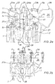
- the cylinder head 1 partially shown in FIG. 1 is a four-valve cylinder head for a particularly four-cylinder self-igniting Internal combustion engine.
- the cylinder head 1 is with cylinder head screws 2 (Fig. 2) screwed onto the crankcase of an internal combustion engine, wherein a cylinder 3 and a piston 4 are indicated in FIG. 1 are.
- the cylinder head 1 is covered by a camshaft bearing frame 5a, the one with camshaft bearing frame fastening screws 6 is screwed onto the cylinder head 1.
- a separate cover 7 is placed, which in turn is covered by a mounting space cover 8 (Fig. 3).
- a recess 9 for each cylinder let in, which extends through the cylinder head 1 into the in the piston 4 embedded combustion chamber continues.
- an injection valve 10 is used, which with a mounting bracket 11 with an injector fastening screw 12 on a support element 35 is attached.
- the injection valve 10 has an overhead or side injector high-pressure line connection 13 (Fig. 3) and a drain line connection 36.
- the recess 9 is perpendicular in the central plane of the cylinder head 1 and Camshaft bearing frame 5a arranged and exactly or possibly with a slight lateral offset in the extension of the central axis of the associated Cylinder aligned.
- the recess 9 is also in the central plane through the cylinder head 1 and Camshaft bearing frame 5a arranged a second recess 14, the obliquely to the recess 9 also into the combustion chamber of the Piston 4 extends.
- a glow plug 15 is in this second recess 14 screwed in or inserted, with a cable connection 16 with the electrical system of the internal combustion engine is connected.
- the recess 9 and the second recess 14 go in the Camshaft bearing frame 5a in a mounting space 17, which itself over almost the entire length of the camshaft bearing frame (Fig. 4 and 5) extends.
- a recess 18 embedded in the cylinder head one of which is on the side Disposal opening 19 goes to a cylinder head longitudinal side wall.
- the mouths of the disposal openings 19 of a row of cylinders can be connected to one another (and with a Collecting container).
- In the cylinder head 1 are still Conventional coolant spaces 20b let in, through which cooling water flows become.
- the cylinder head 1 has a cast one along about the middle of the cylinder head 1 bypassing the side the recesses 9 and the second recesses 14 extending Oil gallery 20a, through the lubricating oil to the lubrication points and Hydraulic ram is guided. Underneath are unpressurized oil spaces 20c.
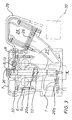
- FIGS. 2a and 2b Camshaft bearing frame 5b with an integrated cover plate 21 fitted. Accordingly, the cylinder head bolts are in extension 2 and next to the camshaft bearing frame mounting screws 6 openings 22 are provided by caps 23a, 23b are closable. Here are the caps 23a and 23b can be configured differently.
- the internal combustion engine has two overhead camshafts 24a, 24b, whose central axis through the parting plane 25 between cylinder head 1 and Camshaft bearing frame 5b runs. In the right part of the Fig. 2 shows the air intake line, also from the parting plane 25 is divided into a lower and an upper part.
- the Air intake line which can also be a charge air line, is over Intake ports 27 connected to the intake valves of a cylinder. Furthermore, through the parting line 25 from the air intake line 26 separate cover 28 in one piece with the camshaft bearing frame 5b trained. Moreover, flats 40 are shown in FIG. 2a shown on the camshafts 24a, 24b, each in the mounting position stand for the cylinder head screws 2.
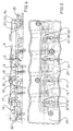
- Fig. 3 is the camshaft bearing frame 5c with a separate Cover 7 shown, in particular two in this figure different installation options of the injection line 29 are shown are.
- the injection line 29 is on in both variants the side injector high pressure line connection 13 screwed and to the injection pump 30, which acts as a high-pressure distributor injection pump is trained, led. Alternatively, use is also possible a common rail system.
- the injection line 29 through an opening 31, which is through the camshaft bearing frame 5c and possibly the cylinder head 1 extends to a side wall of the cylinder head 1.
- cover 7 that this is sealed by sealing strips 32 and acoustically decoupled attached to the camshaft bearing frame 5a is and in particular also sealed to the central assembly space 17 is.
- the assembly space cover 8 is a plastic part trained and simple (as can also be seen in FIGS. 4 and 5) clipped on.
- a camshaft bearing frame 5c is shown, which in turn has an integrated cover plate 21.
- the camshaft bearing frame mounting screws 6 up to guided the cover plate 21 and sealed against this.
- injection line 29 is coaxial with the injection valve 10 screwed tight.
- a gear space 33 is also shown, which is molded onto the camshaft bearing frame 5a.
- the gear room 33 comb the camshaft gears 37 of the camshafts 24a, 24b with each other.
- the first camshaft is driven 24 from a toothed belt wheel 39.
Landscapes
- Engineering & Computer Science (AREA)
- Mechanical Engineering (AREA)
- General Engineering & Computer Science (AREA)
- Valve-Gear Or Valve Arrangements (AREA)
- Cylinder Crankcases Of Internal Combustion Engines (AREA)
Applications Claiming Priority (2)
| Application Number | Priority Date | Filing Date | Title |
|---|---|---|---|
| DE19729948 | 1997-07-12 | ||
| DE19729948A DE19729948A1 (de) | 1997-07-12 | 1997-07-12 | Nockenwellenlagerrahmen |
Publications (3)
| Publication Number | Publication Date |
|---|---|
| EP0890713A2 true EP0890713A2 (fr) | 1999-01-13 |
| EP0890713A3 EP0890713A3 (fr) | 1999-03-31 |
| EP0890713B1 EP0890713B1 (fr) | 2003-03-26 |
Family
ID=7835529
Family Applications (1)
| Application Number | Title | Priority Date | Filing Date |
|---|---|---|---|
| EP98110042A Expired - Lifetime EP0890713B1 (fr) | 1997-07-12 | 1998-05-29 | Moteur à combustion interne avec cadre de support pour arbre à cames |
Country Status (2)
| Country | Link |
|---|---|
| EP (1) | EP0890713B1 (fr) |
| DE (2) | DE19729948A1 (fr) |
Cited By (1)
| Publication number | Priority date | Publication date | Assignee | Title |
|---|---|---|---|---|
| WO2003106832A1 (fr) * | 2002-06-15 | 2003-12-24 | Daimlerchrysler Ag | Culasse de moteur a combustion interne a piston alternatif |
Citations (1)
| Publication number | Priority date | Publication date | Assignee | Title |
|---|---|---|---|---|
| DE4121504A1 (de) | 1990-09-13 | 1992-03-26 | Skoda Automobilova | Zylinderkopf |
Family Cites Families (17)
| Publication number | Priority date | Publication date | Assignee | Title |
|---|---|---|---|---|
| FR2528511A1 (fr) * | 1982-06-14 | 1983-12-16 | Peugeot | Chapeau de palier pour arbre a cames en tete de moteur a combustion interne, et moteur correspondant |
| JPS6176712A (ja) * | 1984-09-21 | 1986-04-19 | Nissan Motor Co Ltd | 内燃機関の動弁装置 |
| GB2181486B (en) * | 1985-10-11 | 1989-02-15 | Honda Motor Co Ltd | Camshaft support assembly for valve operating mechanism in an internal combustion engine |
| FR2615905B1 (fr) * | 1987-05-29 | 1989-09-15 | Renault | Culasse multisoupapes pour moteur a combustion interne |
| JP2717828B2 (ja) * | 1988-12-09 | 1998-02-25 | ヤマハ発動機株式会社 | シリンダヘッドの締結構造 |
| DE3912495C2 (de) * | 1989-04-15 | 1998-07-16 | Audi Ag | Nockenwellengehäuse |
| DE3913844A1 (de) * | 1989-04-27 | 1990-10-31 | Audi Ag | Brennkraftmaschine mit mindestens einer obenliegenden nockenwelle |
| JP2829866B2 (ja) * | 1989-07-14 | 1998-12-02 | ヤマハ発動機株式会社 | 4サイクルエンジンの潤滑装置 |
| AT404864B (de) * | 1989-10-25 | 1999-03-25 | Avl Verbrennungskraft Messtech | Brennkraftmaschine mit mehr als zwei ventilen je zylinder |
| DE3943729C2 (de) * | 1989-12-11 | 1995-07-13 | Porsche Ag | Zylinderkopf einer Brennkraftmaschine |
| DE4017048C2 (de) * | 1990-05-26 | 1994-05-05 | Opel Adam Ag | Zylinderkopf |
| FR2663366B1 (fr) * | 1990-06-15 | 1994-09-16 | Peugeot | Agencement d'arbre a cames dans la culasse d'un moteur a combustion interne. |
| DE4116944C2 (de) * | 1991-05-24 | 1997-05-22 | Daimler Benz Ag | Zylinderkopf für eine mehrzylindrige Brennkraftmaschine |
| DE4227566A1 (de) * | 1992-08-20 | 1994-03-03 | Daimler Benz Ag | Zylinderkopfseitiges Nockenwellenlager für eine mehrzylindrige Brennkraftmaschine |
| DE4323073A1 (de) * | 1993-07-10 | 1995-01-12 | Audi Ag | Hubkolben-Brennkraftmaschine |
| DE4324791A1 (de) * | 1993-07-23 | 1995-01-26 | Porsche Ag | Zylinderkopfanordnung einer Brennkraftmaschine |
| DE19603692A1 (de) * | 1996-02-02 | 1997-08-07 | Mbi Maschinen Und Bauingenieur | Zylinderkopfdeckel mit integrierter Nockenwellen-Lagergasse für Kolbenverbrennungsmotoren |
-
1997
- 1997-07-12 DE DE19729948A patent/DE19729948A1/de not_active Withdrawn
-
1998
- 1998-05-29 EP EP98110042A patent/EP0890713B1/fr not_active Expired - Lifetime
- 1998-05-29 DE DE59807616T patent/DE59807616D1/de not_active Expired - Fee Related
Patent Citations (1)
| Publication number | Priority date | Publication date | Assignee | Title |
|---|---|---|---|---|
| DE4121504A1 (de) | 1990-09-13 | 1992-03-26 | Skoda Automobilova | Zylinderkopf |
Cited By (1)
| Publication number | Priority date | Publication date | Assignee | Title |
|---|---|---|---|---|
| WO2003106832A1 (fr) * | 2002-06-15 | 2003-12-24 | Daimlerchrysler Ag | Culasse de moteur a combustion interne a piston alternatif |
Also Published As
| Publication number | Publication date |
|---|---|
| DE59807616D1 (de) | 2003-04-30 |
| EP0890713B1 (fr) | 2003-03-26 |
| DE19729948A1 (de) | 1999-01-14 |
| EP0890713A3 (fr) | 1999-03-31 |
Similar Documents
| Publication | Publication Date | Title |
|---|---|---|
| DE102011088141B4 (de) | Zylinderblockanordnung | |
| DE3414710A1 (de) | Verbrennungsmotor mit v-foermiger zylinderanordnung | |
| DE60303039T2 (de) | Brennkraftmaschine | |
| DE10033367C2 (de) | Brennkraftmaschine, insbesondere für Motorräder | |
| DE3050893C2 (fr) | ||
| DE19652049C1 (de) | Brennkraftmaschine und Verfahren zu deren Herstellung | |
| EP0251159B1 (fr) | Conduit de retour pour des gaz de fuite d'une boîte de manivelle | |
| DE60016895T2 (de) | Vorrichtung für brennkraftmaschinen | |
| DE69414557T2 (de) | Zylinderkopfanordnung für eine Mehrventil-Brennkraftmaschine mit obenliegender Nockenwelle | |
| WO1996009467A1 (fr) | Culasse | |
| DE3400926C2 (fr) | ||
| EP0890713B1 (fr) | Moteur à combustion interne avec cadre de support pour arbre à cames | |
| EP2627884B1 (fr) | Moteur à combustion interne et procédé de fabrication d'un tel moteur à combustion interne | |
| EP0890726B1 (fr) | Culasse à quatre soupapes agencées inclinées | |
| DE19548329C2 (de) | Otto-Verbrennungsmotor mit Kraftstoffeinspritzventil | |
| DE69006127T2 (de) | Eine Luftansaugvorrichtung für eine Brennkraftmaschine. | |
| EP1146219A1 (fr) | Moteur à combustion interne avec des cylindres disposés en V | |
| EP0782667B1 (fr) | Tubulure d'air de combustion d'un moteur a combustion interne | |
| DE19849912A1 (de) | Flüssigkeitsgekühlte Brennkraftmaschine | |
| DE102006016777B4 (de) | Fahrzeug vom Typ mit einem Sattel mit Hochdruck-Kraftstoffpumpe | |
| DE19959989A1 (de) | Lagerung zumindest einer Nockenwelle | |
| DE4338186A1 (de) | Hubkolbenbrennkraftmaschine | |
| EP0782668B1 (fr) | Carter intermediaire pour moteur a combustion interne | |
| DE4230528A1 (de) | Brennkraftmaschine | |
| DE10042036C2 (de) | Brennkraftmaschine |
Legal Events
| Date | Code | Title | Description |
|---|---|---|---|
| PUAI | Public reference made under article 153(3) epc to a published international application that has entered the european phase |
Free format text: ORIGINAL CODE: 0009012 |
|
| AK | Designated contracting states |
Kind code of ref document: A2 Designated state(s): DE ES FR GB IT PT SE |
|
| AX | Request for extension of the european patent |
Free format text: AL;LT;LV;MK;RO;SI |
|
| PUAL | Search report despatched |
Free format text: ORIGINAL CODE: 0009013 |
|
| RTI1 | Title (correction) | ||
| AK | Designated contracting states |
Kind code of ref document: A3 Designated state(s): AT BE CH CY DE DK ES FI FR GB GR IE IT LI LU MC NL PT SE |
|
| AX | Request for extension of the european patent |
Free format text: AL;LT;LV;MK;RO;SI |
|
| 17P | Request for examination filed |
Effective date: 19990806 |
|
| AKX | Designation fees paid |
Free format text: DE ES FR GB IT PT |
|
| RBV | Designated contracting states (corrected) |
Designated state(s): AT DE ES FR GB IT PT |
|
| RBV | Designated contracting states (corrected) |
Designated state(s): DE ES FR GB IT PT SE |
|
| 17Q | First examination report despatched |
Effective date: 20011002 |
|
| RTI1 | Title (correction) |
Free format text: INTERNAL COMBUSTION ENGINE WITH CAMSHAFT BEARING FRAME |
|
| GRAH | Despatch of communication of intention to grant a patent |
Free format text: ORIGINAL CODE: EPIDOS IGRA |
|
| GRAH | Despatch of communication of intention to grant a patent |
Free format text: ORIGINAL CODE: EPIDOS IGRA |
|
| GRAA | (expected) grant |
Free format text: ORIGINAL CODE: 0009210 |
|
| AK | Designated contracting states |
Designated state(s): DE ES FR GB IT PT SE |
|
| PG25 | Lapsed in a contracting state [announced via postgrant information from national office to epo] |
Ref country code: IT Free format text: LAPSE BECAUSE OF FAILURE TO SUBMIT A TRANSLATION OF THE DESCRIPTION OR TO PAY THE FEE WITHIN THE PRE;WARNING: LAPSES OF ITALIAN PATENTS WITH EFFECTIVE DATE BEFORE 2007 MAY HAVE OCCURRED AT ANY TIME BEFORE 2007. THE CORRECT EFFECTIVE DATE MAY BE DIFFERENT FROM THE ONE RECORDED.SCRIBED TIME-LIMIT Effective date: 20030326 |
|
| REG | Reference to a national code |
Ref country code: GB Ref legal event code: FG4D Free format text: NOT ENGLISH |
|
| REF | Corresponds to: |
Ref document number: 59807616 Country of ref document: DE Date of ref document: 20030430 Kind code of ref document: P |
|
| PG25 | Lapsed in a contracting state [announced via postgrant information from national office to epo] |
Ref country code: PT Free format text: LAPSE BECAUSE OF FAILURE TO SUBMIT A TRANSLATION OF THE DESCRIPTION OR TO PAY THE FEE WITHIN THE PRESCRIBED TIME-LIMIT Effective date: 20030626 |
|
| REG | Reference to a national code |
Ref country code: SE Ref legal event code: TRGR |
|
| GBT | Gb: translation of ep patent filed (gb section 77(6)(a)/1977) | ||
| PG25 | Lapsed in a contracting state [announced via postgrant information from national office to epo] |
Ref country code: ES Free format text: LAPSE BECAUSE OF FAILURE TO SUBMIT A TRANSLATION OF THE DESCRIPTION OR TO PAY THE FEE WITHIN THE PRESCRIBED TIME-LIMIT Effective date: 20030930 |
|
| ET | Fr: translation filed | ||
| PLBE | No opposition filed within time limit |
Free format text: ORIGINAL CODE: 0009261 |
|
| STAA | Information on the status of an ep patent application or granted ep patent |
Free format text: STATUS: NO OPPOSITION FILED WITHIN TIME LIMIT |
|
| 26N | No opposition filed |
Effective date: 20031230 |
|
| PGFP | Annual fee paid to national office [announced via postgrant information from national office to epo] |
Ref country code: FR Payment date: 20050411 Year of fee payment: 8 |
|
| PGFP | Annual fee paid to national office [announced via postgrant information from national office to epo] |
Ref country code: GB Payment date: 20050413 Year of fee payment: 8 |
|
| PGFP | Annual fee paid to national office [announced via postgrant information from national office to epo] |
Ref country code: SE Payment date: 20050419 Year of fee payment: 8 |
|
| PGFP | Annual fee paid to national office [announced via postgrant information from national office to epo] |
Ref country code: DE Payment date: 20050525 Year of fee payment: 8 |
|
| PG25 | Lapsed in a contracting state [announced via postgrant information from national office to epo] |
Ref country code: GB Free format text: LAPSE BECAUSE OF NON-PAYMENT OF DUE FEES Effective date: 20060529 |
|
| PG25 | Lapsed in a contracting state [announced via postgrant information from national office to epo] |
Ref country code: SE Free format text: LAPSE BECAUSE OF NON-PAYMENT OF DUE FEES Effective date: 20060530 |
|
| PG25 | Lapsed in a contracting state [announced via postgrant information from national office to epo] |
Ref country code: DE Free format text: LAPSE BECAUSE OF NON-PAYMENT OF DUE FEES Effective date: 20061201 |
|
| EUG | Se: european patent has lapsed | ||
| GBPC | Gb: european patent ceased through non-payment of renewal fee |
Effective date: 20060529 |
|
| REG | Reference to a national code |
Ref country code: FR Ref legal event code: ST Effective date: 20070131 |
|
| PG25 | Lapsed in a contracting state [announced via postgrant information from national office to epo] |
Ref country code: FR Free format text: LAPSE BECAUSE OF NON-PAYMENT OF DUE FEES Effective date: 20060531 |