EP0890765A1 - Commande hydraulique de transmission automatique - Google Patents
Commande hydraulique de transmission automatique Download PDFInfo
- Publication number
- EP0890765A1 EP0890765A1 EP98112665A EP98112665A EP0890765A1 EP 0890765 A1 EP0890765 A1 EP 0890765A1 EP 98112665 A EP98112665 A EP 98112665A EP 98112665 A EP98112665 A EP 98112665A EP 0890765 A1 EP0890765 A1 EP 0890765A1
- Authority
- EP
- European Patent Office
- Prior art keywords
- pressure
- torque converter
- port
- passage
- valve
- Prior art date
- Legal status (The legal status is an assumption and is not a legal conclusion. Google has not performed a legal analysis and makes no representation as to the accuracy of the status listed.)
- Granted
Links
- 230000005540 biological transmission Effects 0.000 title claims abstract description 38
- 238000005461 lubrication Methods 0.000 claims abstract description 70
- 239000012530 fluid Substances 0.000 claims abstract description 57
- 239000003607 modifier Substances 0.000 claims description 14
- 238000006073 displacement reaction Methods 0.000 claims description 10
- 230000008901 benefit Effects 0.000 description 2
- 238000010586 diagram Methods 0.000 description 2
- 230000002411 adverse Effects 0.000 description 1
- 210000000078 claw Anatomy 0.000 description 1
- 238000010276 construction Methods 0.000 description 1
- 230000001050 lubricating effect Effects 0.000 description 1
- 230000001105 regulatory effect Effects 0.000 description 1
Images



Classifications
-
- F—MECHANICAL ENGINEERING; LIGHTING; HEATING; WEAPONS; BLASTING
- F16—ENGINEERING ELEMENTS AND UNITS; GENERAL MEASURES FOR PRODUCING AND MAINTAINING EFFECTIVE FUNCTIONING OF MACHINES OR INSTALLATIONS; THERMAL INSULATION IN GENERAL
- F16H—GEARING
- F16H57/00—General details of gearing
- F16H57/04—Features relating to lubrication or cooling or heating
-
- F—MECHANICAL ENGINEERING; LIGHTING; HEATING; WEAPONS; BLASTING
- F16—ENGINEERING ELEMENTS AND UNITS; GENERAL MEASURES FOR PRODUCING AND MAINTAINING EFFECTIVE FUNCTIONING OF MACHINES OR INSTALLATIONS; THERMAL INSULATION IN GENERAL
- F16H—GEARING
- F16H61/00—Control functions within control units of change-speed- or reversing-gearings for conveying rotary motion ; Control of exclusively fluid gearing, friction gearing, gearings with endless flexible members or other particular types of gearing
- F16H61/14—Control of torque converter lock-up clutches
- F16H61/143—Control of torque converter lock-up clutches using electric control means
-
- F—MECHANICAL ENGINEERING; LIGHTING; HEATING; WEAPONS; BLASTING
- F16—ENGINEERING ELEMENTS AND UNITS; GENERAL MEASURES FOR PRODUCING AND MAINTAINING EFFECTIVE FUNCTIONING OF MACHINES OR INSTALLATIONS; THERMAL INSULATION IN GENERAL
- F16H—GEARING
- F16H61/00—Control functions within control units of change-speed- or reversing-gearings for conveying rotary motion ; Control of exclusively fluid gearing, friction gearing, gearings with endless flexible members or other particular types of gearing
- F16H61/02—Control functions within control units of change-speed- or reversing-gearings for conveying rotary motion ; Control of exclusively fluid gearing, friction gearing, gearings with endless flexible members or other particular types of gearing characterised by the signals used
- F16H61/0202—Control functions within control units of change-speed- or reversing-gearings for conveying rotary motion ; Control of exclusively fluid gearing, friction gearing, gearings with endless flexible members or other particular types of gearing characterised by the signals used the signals being electric
- F16H61/0251—Elements specially adapted for electric control units, e.g. valves for converting electrical signals to fluid signals
- F16H2061/0253—Details of electro hydraulic valves, e.g. lands, ports, spools or springs
Definitions
- This invention relates to a hydraulic control device for an automatic transmission for an automotive vehicle which incorporates a lock up clutch.
- a kind of automatic speed change mechanism for an automotive vehicle comprising a system which combines a torque converter equipped with a lock up clutch and an automatic transmission equipped with a forward/reverse change-over mechanism has, for example, been disclosed in Tokkai Hei 4-78369 published by the Japanese Patent Office in 1992.
- control of the speed changing of the automatic transmission, engagement and disengagement of the lock up clutch, and lubrication of the automatic transmission are performed by the use of pressurized hydraulic fluid from a single hydraulic pump.
- Hydraulic fluid which lubricates hydraulic transmission is supplied via a lubrication passage from a torque converter pressure passage which operates the lock up clutch.
- this hydraulic pump may be constructed as a vane pump, the output pressure of such a pump is reduced when the temperature of the hydraulic fluid is high so that its viscosity is low, and also at times of low vehicle speed.
- an orifice is provided between the torque converter pressure passage and the lubrication passage.
- the output pressure of the hydraulic pump may be sufficiently high, the pressure in the torque converter pressure passage is controlled to a set pressure by a relief valve.
- a relief valve As a result, even when the automatic transmission is being subjected to high load, it is difficult to make considerable increases to the flow of hydraulic fluid supplied from the torque converter pressure passage via the orifice to the lubrication passage.
- this invention provides a hydraulic control device for use with an automatic transmission which is connected to a torque converter comprising a lock up clutch.
- the device comprises a pressure control valve which controls hydraulic pressure supplied to the automatic transmission, a torque converter pressure passage which supplies hydraulic fluid for operating the lock up clutch from the pressure control valve to the lock up clutch, a lubrication passage which supplies hydraulic fluid for lubrication to the automatic transmission, an orifice which joins the torque converter pressure passage to the lubrication passage, and a regulator valve which limits the pressure in the torque converter pressure passage to a predetermined upper limit value.
- the device further comprises a bypass valve detouring the orifice for supplying hydraulic fluid from the torque converter pressure passage to the lubrication passage when the pressure in the torque converter pressure passage rises above a predetermined value.
- the bypass valve comprises the regulator valve and the regulator valve comprises a torque converter pressure port which communicates with the torque converter pressure passage, a drain port which vents the pressure in the torque converter pressure passage, a lubrication port which communicates with the lubrication passage, and a member which connects the torque converter pressure port to the drain port and the lubrication port when the pressure in the torque converter pressure passage rises above a predetermined value.
- the device further comprises a solenoid valve which generates a first signal pressure, a solenoid valve which generates a second signal pressure, and a pressure modifier valve which regulates the second signal pressure according to the first signal pressure to produce a third signal pressure
- the pressure control valve comprises a member which controls the pressure supplied to the automatic transmission in accordance with the first signal pressure
- the regulator valve comprises a port which varies the predetermined value according to the third signal pressure.
- the device further comprises a solenoid valve which generates a first signal pressure
- the pressure control valve comprises a member which controls the pressure which is supplied to the automatic transmission in accordance with the first signal pressure
- the bypass valve comprises a lock up regulator valve which comprises a member which fixes the predetermined pressure according to the first signal pressure
- the lock up clutch comprises a first hydraulic fluid chamber which locks up the torque converter and a second hydraulic fluid chamber which unlocks the torque converter, and that the device further comprises a lock up control valve which selectively connects the torque converter pressure passage to either the first hydraulic fluid chamber or the second hydraulic fluid chamber.
- the device further comprises a solenoid valve which generates a first signal pressure
- the bypass valve comprises the aforesaid regulator valve which has a torque converter pressure port which is communicated to the torque converter pressure passage, a drain port which vents the pressure in the torque converter pressure passage, a lubrication port which communicates with the lubrication passage, a signal pressure port to which the first signal pressure is fed, a member which connects the torque converter pressure port to the drain port and the lubrication port when the pressure in the torque converter pressure passage rises above the predetermined value, and a member which adjusts the predetermined value according to the pressure at the signal pressure port.
- the regulator valve further comprises another torque converter pressure port which communicates with the torque converter pressure port
- the connecting member comprises a first spool
- the predetermined pressure adjustment member comprises a second spool which is arranged in series with the first spool with a spring between them
- the signal pressure port exerts the first signal pressure upon one end of the second spool
- the other torque converter pressure port exerts the pressure in the torque converter pressure passage upon one end of the first spool in a direction opposite to the first signal pressure.
- the regulator valve further comprises a stopper which prevents displacement of the second spool due to the pressure at the signal pressure port past a predetermined position.
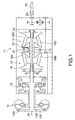
- an automatic transmission system for an automotive vehicle to which this invention is applied comprises a torque converter 12 which is equipped with a lock up clutch 12D, and an automatic transmission 11 which is equipped with a forward/reverse change-over mechanism 13.
- the rotation of an engine not shown in the figures is input to a power input shaft 23 of the torque converter 12, and a power output shaft 24 of the automatic transmission 11 rotates drive wheels of the vehicle via a propeller shaft 25.
- the automatic transmission 11 is a toroidal continuously variable transmission comprising a first toroidal speed change section 16 and a second toroidal speed change section 17.
- first section 16 a power input disk 19 and a power output disk 21 between which power rollers 18A and 18B are squeezed.
- the second toroidal speed change section 17 comprises power input disk 20 and a power output disk 22 between which power rollers 18C and 18D are squeezed. Due to the inclination of the power rollers 18A through 18D being varied by hydraulic fluid pressure this transmission 11 can provide any desired speed change ratio.
- This type of toroidal continuously variable transmission is known from U.S. Patent No. 5,542,890, for example.
- This automatic transmission system is controlled by a hydraulic control device shown in Fig. 2.
- hydraulic fluid which is pressurized by a hydraulic pump 1 which is driven by the engine is supplied to a line pressure passage 30, and is regulated to a predetermined line pressure PL by a pressure control valve 2 provided in the line pressure passage 30.
- the speed change ratio of the automatic transmission 11 is controlled using this line pressure PL .
- the line pressure PL is controlled by a relief valve 42 so as not to exceed a predetermined upper limit.
- the pressure control valve 2 comprises a port 2A to which is supplied a signal pressure PLSOL from a line pressure solenoid valve 40 which is duty ratio controlled by an electronic controller not shown in the figures, and a spool 2E which is driven responsive to the signal pressure PLSOL led to the port 2A.
- This signal pressure PLSOL corresponds to the first signal pressure of the claims.
- This pressure control valve 2 communicates a port 2C which leads to the line pressure passage 30 either to a port 2B or to a drain port 2D, according to the displacement of the spool 2E.
- the port 2B is connected to a torque converter pressure passage 31 which operates the lock up clutch 12D of the torque converter 12.
- the drain port 2D is connected via a strainer to an intake port 1A of the hydraulic pump 1, and recirculates the hydraulic fluid in the line pressure passage 30 to the intake side of the hydraulic pump 1.
- the pressure control valve 2 regulates both the line pressure PL and also the pressure PT/C in the torque converter pressure passage 31 in response to the signal pressure PLSOL .
- a lock up control valve 5 In the torque converter pressure passage 31 there are provided a lock up control valve 5, a T/C regulator valve 3, a lock up regulator valve 4, and an orifice 8.
- the lock up control valve 5 comprises a spool 5E which is driven in response to a signal pressure PL/USOL from a lock up solenoid valve 41 which is duty controlled by the electronic controller.
- the pressure PT/C is selectively supplied either via a port 5G to a first hydraulic fluid chamber 12E of the lock up clutch 12D, or via a port 5H to a second hydraulic fluid chamber 12F of the lock up clutch 12D.
- This signal pressure PL/USOL corresponds to the second signal pressure of the claims.
- the lock up control valve 5 further comprises a port 5C which is connected to a lubrication passage 37, and in response to the displacement of the spool 5E, this port 5C is connected to a port 5F which leads to an oil cooler 32 and a main lubrication passage 33.
- the main lubrication passage 33 supplies hydraulic fluid to such areas as the rotational shafts of the first and second toroidal speed change sections 16 and 17 of the automatic transmission 11 for the purpose of lubrication.
- the lubrication passage 37 is further connected to a front section lubrication passage 34 via an orifice 7 and a check valve 70.
- the front section lubrication passage 34 is a passage which supplies hydraulic fluid to the forward/reverse change-over mechanism 13 of the automatic transmission 11 for the purpose of lubrication.
- the T/C regulator valve 3 is a valve which controls the pressure PT/C to be within an upper limit pressure withstand value PT/Cmax for the torque converter 12, and comprises a torque converter pressure port 3C which is connected to the torque converter pressure passage 31, a lubrication port 3B, and a drain port 3D.
- the lubrication port 3B is connected to a lubrication passage 37, while the drain port 3D is connected via a strainer to the intake port 1A of the hydraulic pump 1.
- This T/C regulator valve 3 selectively connects the torque converter pressure port 3C to the lubrication port 3B or to the drain port 3D according to the displacement of a spool 3E which is driven responsive to the balance between the pressure PT/C and the pressure of a spring which is opposed thereto.
- the lock up regulator valve 4 is a valve for ensuring the supply pressure to the first hydraulic fluid chamber 12E of the torque converter 12 in precedence to the supply of hydraulic fluid to the main lubrication passage 33 and front section lubrication passage 34.
- This lock up regulator valve 4 comprises a port 4B which is connected to the lubrication passage 37, a port 4C which is connected to the torque converter pressure passage 31, and a port 4D to which the signal pressure PLSOL is fed, and it connects the ports 4B and 4C together according to the displacement of the spool 4E.
- the torque converter pressure PT/C acts upon one end of the spool 4E, and the signal pressure PLSOL acts on the other end of the spool 4E via the port 4D. Further, a spring assists the signal pressure PLSOL .
- the spool 4E either connects or disconnects the torque converter pressure passage 31 and the lubrication passage 37, and so obtains the pressure necessary for the engagement of the lock up clutch 12D, by giving priority to the torque converter pressure PT/C in the torque converter pressure passage 31 over the supply of hydraulic fluid to the lubrication passage 37.
- a relief valve 36 is provided in the torque converter pressure passage 31. This relief valve 36 prevents excessive pressure from being supplied to the first hydraulic fluid chamber 12E and the second hydraulic fluid chamber 12F, if for example the lock up control valve 5 freezes.
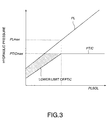
- the hydraulic pump 1 which is driven by the engine expels pressurized hydraulic fluid into the line pressure passage 30, and the pressure control valve 2 controls the line pressure PL in this line pressure passage 30 so as to keep it proportional to the signal pressure PLSOL from the line pressure solenoid valve 40, as shown in Fig. 3.
- the pressure of the pressurized hydraulic fluid which flows into the torque converter pressure passage 31 from the line pressure passage 30 via the port 2B of the pressure control valve 2 is kept lower than the upper limit value PT/Cmax by the T/C regulator valve 3.
- this pressurized hydraulic fluid is supplied to the lubrication passage 37 via the port 4B of the lock up regulator valve 4, the lock up regulator valve 4 performs pressure control to ensure the torque converter pressure PT/C required for the engagement of the lock up clutch 12D rather to supply hydraulic fluid to the lubricating passage 37.
- the lock up regulator valve 4 as shown in Fig. 2 displaces the spool 4E to the right as seen in the figure according to an increase in the signal pressure PLSOL , and cuts off the port 4C until the ratio between the torque converter pressure PT/C and the signal pressure PLSOL exceeds a predetermined value.
- a torque converter pressure PT/C which is sufficient for engagement of the lock up clutch 12D. It should be noted that even in this case a small quantity of hydraulic fluid is supplied to the lubrication passage 37 from the torque converter pressure passage 31 via the orifice 8.
- the port 4C opens according to the balance between the signal pressure PLSOL and the torque converter pressure PT/C .
- the lower limit value for the torque converter pressure PT/C is accordingly raised along with the signal pressure PLSOL , as shown in Fig. 3.
- the torque converter pressure PT/C maintains a relationship between the line pressure PL and the lower limit value as shown by the sloping line in the figure.
- the torque converter pressure PT/C is maintained at the set pressure PT/Cmax of the T/C regulator valve 3.
- the lock up regulator valve 4 supplies hydraulic fluid from its port 4C to its port 4B, and supplies hydraulic fluid to the lubrication passage 37, so that the lubrication of the automatic transmission 11 does not fail.
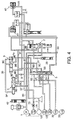
- Figs. 4 and 5 show a second embodiment of this invention.
- a pressure modifier valve 9 is provided instead of the lock up regulator valve 4 of the first embodiment described above.
- This pressure modifier valve 9 comprises ports 9B, 9C, and 9D, and the ports 9B and 9C are communicated together by the displacement of a spool 9E.
- the port 9D is formed so as to face one end of the spool 9E, and the signal pressure PLSOL is fed to this port 9D from the line pressure solenoid valve 40.
- the pressure modifier valve 9 further comprises a spring which biases the spool 9E in the same direction.
- the signal pressure PL/USOL is fed to the port 9B from the lock up solenoid valve 41 as a constant pressure Pp , so as to oppose the signal pressure PLSOL .
- the spool 9E is displaced in response to the signal pressure PLSOL, and the pressure level of the hydraulic fluid at the port 9B is modified according the position to which said spool 9E is displaced, and is supplied to the port 9C as a pressure modifier pressure PMF .
- This pressure modifier pressure PMF corresponds to the third signal pressure of the claims.
- the port 9c is connected via a hydraulic fluid passage 35 to a port 3F which faces the base end of the spool 3E of the T/C regulator valve 3.
- the pressure modifier pressure PMF and the pressure of the spring are applied at one end of the spool 3E of the T/C regulator valve 3.
- the torque converter pressure PT/C acts upon the other end of the spool 3E so as to oppose these pressures, in the same way as in the first embodiment described above.
- the spool 3E connects the torque converter pressure port 3C, to which is fed the pressure in the torque converter pressure passage 31, either to the lubrication port 3B which is connected to the lubrication passage 37, or to the drain port 3D which is connected to the intake port 1A of the hydraulic pump 1.
- the T/C regulator valve 3 performs control so as to keep the torque converter pressure PT/C within a range in which it does not exceed its upper limit value PT/Cmax, and moreover so as to keep it at the pressure which is required for engagement of the lock up clutch 12D.
- the pressure modifier valve 9 increases the pressure modifier pressure PMF in accordance with increase of the signal pressure PLSOL until the signal pressure PLSOL reaches a predetermined value P1 , as shown in Fig. 5. Further, the T/C regulator valve 3 increases the torque converter pressure PT/C in the torque converter pressure passage 31 in accordance with increase of the pressure modifier pressure PMF from the T/C regulator valve 3.
- the pressure modifier pressure PMF becomes equal to the constant pressure Pp which is applied to the port 9B. At this time, the pressure modifier pressure PMF is set so that the torque converter pressure PT/C comes to be equal to its upper limit value PT/Cmax .
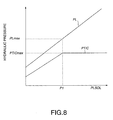
- Figs. 6 through 8 show a third embodiment of this invention.
- This embodiment is one in which the T/C regulator valve 3 of the first embodiment and the lock up regulator valve 4 are combined into a single T/C regulator valve 103, as shown in Fig. 6.
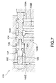
- This T/C regulator valve 103 comprises two spools 104 and 105 arranged in series with a spring 106 between them, as shown in Fig. 7.
- This T/C regulator valve 103 further comprises a torque converter pressure port 103C which is connected to the torque converter pressure passage 31, another torque converter pressure port 103A which allows the torque converter pressure PT/C to act upon the spool 104 in its axial direction, a lubrication port 103B which is connected to the lubrication passage 37, and a drain port 103D which is connected to the intake port 1A of the hydraulic pump 1.
- the spool 105 is arranged to be coaxial with the spool 104.
- the T/C regulator valve 103 comprises a signal pressure port 103E through which the signal pressure PLSOL acts upon the spool 105 in its axial direction.
- the spool 105 is pressed towards and against the spool 104 in response to increase of this signal pressure PLSOL .
- a sleeve 107 which houses the spool 105 there is formed a claw shaped stopper 109 which prevents further displacement of the spool 105 towards the side of the spool 104 when it exceeds a predetermined value.
- the torque converter pressure PT/C Since the line pressure is low in the region where the signal pressure PLSOL is low, the torque converter pressure PT/C is also low. In this case, the spool 105 biases the spool 104 in the rightward direction in Figs. 6 and 7 via the spring 106 with increases in the signal pressure PLSOL . As a result of this pressure the spool 104 is kept in its position in which its ports 103B and 103D are cut off from one another, as shown in the figures. Due to this, dropping of the torque converter pressure PT/C is prevented, and sufficient hydraulic fluid pressure for locking up thereof is assured.
- a torque converter pressure PT/C which is required for locking up is ensured when the line pressure PL is low while, in the high load condition when the line pressure PL becomes high, the supply of hydraulic fluid for lubrication to the main lubrication passage 33 and the front section lubrication passage 34 is increased. Moreover, this has a desirable benefit for the durability of the torque converter 12, since the torque converter pressure PT/C is controlled so as to be kept below its predetermined upper limit value PT/Cmax .
- the limit value PT/Cmax is controlled and also a required torque converter pressure PT/C for lock up is ensured, the number of valves in the hydraulic control device is reduced, which makes it possible to reduce the size and weight of the hydraulic control device.
- the T/C regulator valve 3, the lock up regulator valve 4, and the T/C regulator valve 103 together constitute a bypass valve.
Landscapes
- Engineering & Computer Science (AREA)
- General Engineering & Computer Science (AREA)
- Mechanical Engineering (AREA)
- Control Of Fluid Gearings (AREA)
- Control Of Transmission Device (AREA)
Applications Claiming Priority (2)
| Application Number | Priority Date | Filing Date | Title |
|---|---|---|---|
| JP18399397A JP3635190B2 (ja) | 1997-07-09 | 1997-07-09 | 自動変速機の油圧制御装置 |
| JP183993/97 | 1997-07-09 |
Publications (2)
| Publication Number | Publication Date |
|---|---|
| EP0890765A1 true EP0890765A1 (fr) | 1999-01-13 |
| EP0890765B1 EP0890765B1 (fr) | 2008-09-24 |
Family
ID=16145450
Family Applications (1)
| Application Number | Title | Priority Date | Filing Date |
|---|---|---|---|
| EP98112665A Expired - Lifetime EP0890765B1 (fr) | 1997-07-09 | 1998-07-08 | Commande hydraulique de transmission automatique |
Country Status (4)
| Country | Link |
|---|---|
| US (1) | US6056094A (fr) |
| EP (1) | EP0890765B1 (fr) |
| JP (1) | JP3635190B2 (fr) |
| DE (1) | DE69840041D1 (fr) |
Cited By (1)
| Publication number | Priority date | Publication date | Assignee | Title |
|---|---|---|---|---|
| CN103591281A (zh) * | 2012-06-18 | 2014-02-19 | 通用汽车环球科技运作有限责任公司 | 无级变速器的液压控制系统 |
Families Citing this family (13)
| Publication number | Priority date | Publication date | Assignee | Title |
|---|---|---|---|---|
| JP3592093B2 (ja) * | 1998-08-10 | 2004-11-24 | ジヤトコ株式会社 | トロイダル型無段自動変速機の潤滑構造 |
| JP2001330140A (ja) * | 2000-05-22 | 2001-11-30 | Toyota Motor Corp | 車両用クラッチの制御装置 |
| US20030155182A1 (en) * | 2000-07-07 | 2003-08-21 | Bernhard Sich | Device and method for accurately supplying components of an automatic gearbox for motor vehicles |
| JP4178952B2 (ja) * | 2002-12-27 | 2008-11-12 | アイシン・エィ・ダブリュ株式会社 | ロックアップ機構の油圧制御装置 |
| DE112005000055B4 (de) * | 2004-07-16 | 2013-11-07 | Komatsu Ltd. | Schmierölzuführung-Steuervorrichtung für ein Wechselgetriebe |
| US7677373B2 (en) * | 2007-05-31 | 2010-03-16 | Dana Heavy Vehicle Systems Group, Llc | Lock-up clutch control method |
| JP4862830B2 (ja) * | 2008-01-24 | 2012-01-25 | トヨタ自動車株式会社 | 流体伝動装置用の制御装置 |
| JP5125604B2 (ja) * | 2008-02-27 | 2013-01-23 | マツダ株式会社 | 自動変速機の油圧制御装置 |
| US8275530B2 (en) * | 2010-09-20 | 2012-09-25 | Sonnax Industries, Inc. | Apparatus and method for increasing transmission line fluid pressure |
| JP5692030B2 (ja) * | 2011-12-01 | 2015-04-01 | トヨタ自動車株式会社 | 車両用油圧制御装置 |
| JP6007746B2 (ja) * | 2012-11-20 | 2016-10-12 | アイシン精機株式会社 | 作動油供給装置 |
| US9506548B2 (en) | 2014-03-12 | 2016-11-29 | Ford Global Technologies | Control valve and method of controlling torque converter lock-up clutch |
| JP6473473B2 (ja) * | 2017-03-27 | 2019-02-20 | 本田技研工業株式会社 | 弁構造及びそれを用いた油圧回路 |
Citations (4)
| Publication number | Priority date | Publication date | Assignee | Title |
|---|---|---|---|---|
| US4051932A (en) * | 1975-07-16 | 1977-10-04 | Toyota Jidosha Kogyo Kabushiki Kaisha | Fluid pressure control system for a hydraulic transmission with a lock-up clutch |
| DE3937939A1 (de) * | 1988-12-01 | 1990-06-07 | Zahnradfabrik Friedrichshafen | Steuereinrichtung fuer eine reibschluessige ueberbrueckungskupplung eines hydrodynamischen drehmomentwandlers |
| US5090527A (en) * | 1989-09-26 | 1992-02-25 | Jatco Corporation | Pressure control system for lock-up clutch in automotive automatic power transmission with compensation of fluid pressure in low engine speed range |
| US5339935A (en) * | 1990-04-18 | 1994-08-23 | Mazda Motor Corporation | Control system for torque converter |
Family Cites Families (7)
| Publication number | Priority date | Publication date | Assignee | Title |
|---|---|---|---|---|
| JP2680191B2 (ja) * | 1988-12-01 | 1997-11-19 | ツァーンラートファブリーク、フリードリッヒスハーフェン、アクチエンゲゼルシャフト | 流体トルクコンバータの摩擦係合クラッチ制御装置 |
| DE3928048A1 (de) * | 1989-08-25 | 1991-02-28 | Ford Werke Ag | Steuereinrichtung fuer eine ueberbrueckungskupplung eines hydrokinetischen drehmomentwandlers |
| US4998604A (en) * | 1990-02-12 | 1991-03-12 | General Motors Corporation | Variable capacity control apparatus for an automotive torque converter clutch |
| JP2661339B2 (ja) * | 1990-07-19 | 1997-10-08 | 日産自動車株式会社 | 無段変速機のライン圧制御装置 |
| JP2653249B2 (ja) * | 1990-12-28 | 1997-09-17 | トヨタ自動車株式会社 | ロックアップクラッチ付トルクコンバータを備えた車両用ベルト式無段変速機の油圧制御装置 |
| US5163540A (en) * | 1992-02-24 | 1992-11-17 | Saturn Corporation | Control valving for a torque converter and clutch assembly |
| US5513732A (en) * | 1994-08-05 | 1996-05-07 | Ford Motor Company | Regulation of hydraulic pressure in a system having multiple pressure sources |
-
1997
- 1997-07-09 JP JP18399397A patent/JP3635190B2/ja not_active Expired - Fee Related
-
1998
- 1998-07-08 US US09/111,702 patent/US6056094A/en not_active Expired - Fee Related
- 1998-07-08 DE DE69840041T patent/DE69840041D1/de not_active Expired - Fee Related
- 1998-07-08 EP EP98112665A patent/EP0890765B1/fr not_active Expired - Lifetime
Patent Citations (4)
| Publication number | Priority date | Publication date | Assignee | Title |
|---|---|---|---|---|
| US4051932A (en) * | 1975-07-16 | 1977-10-04 | Toyota Jidosha Kogyo Kabushiki Kaisha | Fluid pressure control system for a hydraulic transmission with a lock-up clutch |
| DE3937939A1 (de) * | 1988-12-01 | 1990-06-07 | Zahnradfabrik Friedrichshafen | Steuereinrichtung fuer eine reibschluessige ueberbrueckungskupplung eines hydrodynamischen drehmomentwandlers |
| US5090527A (en) * | 1989-09-26 | 1992-02-25 | Jatco Corporation | Pressure control system for lock-up clutch in automotive automatic power transmission with compensation of fluid pressure in low engine speed range |
| US5339935A (en) * | 1990-04-18 | 1994-08-23 | Mazda Motor Corporation | Control system for torque converter |
Cited By (2)
| Publication number | Priority date | Publication date | Assignee | Title |
|---|---|---|---|---|
| CN103591281A (zh) * | 2012-06-18 | 2014-02-19 | 通用汽车环球科技运作有限责任公司 | 无级变速器的液压控制系统 |
| CN103591281B (zh) * | 2012-06-18 | 2016-11-23 | 通用汽车环球科技运作有限责任公司 | 无级变速器的液压控制系统 |
Also Published As
| Publication number | Publication date |
|---|---|
| US6056094A (en) | 2000-05-02 |
| DE69840041D1 (de) | 2008-11-06 |
| EP0890765B1 (fr) | 2008-09-24 |
| JPH1130307A (ja) | 1999-02-02 |
| JP3635190B2 (ja) | 2005-04-06 |
Similar Documents
| Publication | Publication Date | Title |
|---|---|---|
| US4095486A (en) | Device for controlling a lock-up clutch in an automatic transmission | |
| US6056094A (en) | Hydraulic control device for automatic transmission | |
| US5890509A (en) | Hydraulic temperature compensated cooler bypass control for an automatic transmission | |
| US7828128B2 (en) | Control of fluid pressure in a torque converter of an automatic transmission | |
| EP0043545B1 (fr) | Transmission avec convertisseur de couple et embrayage de "court-circuit" comprenant un système de graissage et de pressurisation | |
| EP0791768A2 (fr) | Régulateur de convertisseur de couple et système de blocage d'embrayage de pontage pour véhicule automobile | |
| EP0117696A1 (fr) | Dispositif hydraulique pour une transmission à variation continue | |
| US4845618A (en) | Hydraulic pressure control for reducing engagement shock of automatic transmission | |
| EP0791765B1 (fr) | Commande du système de lubrification d'une transmission automatique | |
| US5762134A (en) | Hydraulic temperature compensated cooler bypass control for an automatic transmission | |
| US5799260A (en) | System for controlling multiple hydraulic pumps in an automatic transmission | |
| US6471613B1 (en) | Transmission with variable line pressure | |
| US6467262B1 (en) | Emergency hydraulic control for a clutch arranged between an internal combustion engine and a gear box | |
| US6350215B1 (en) | Hydraulic control system for pressure control of a CVT variator with limp home mode | |
| MXPA96006268A (es) | Sistema hidraulico de control de lubricacion parauna transmision automatica | |
| US6364802B1 (en) | Hydraulic control system for a continuously variable transmission | |
| US6826908B1 (en) | Pressure regulator valve assembly | |
| US4506564A (en) | Automatic transmission control pressure regulator | |
| US9683666B2 (en) | Transmission hydraulic control system | |
| US3938631A (en) | Gearing with speed responsive starting clutches | |
| US9951861B2 (en) | Transmission hydraulic control system | |
| US10344858B2 (en) | Transmission park control system | |
| US6622835B2 (en) | Engagement control having a multiplexed hydraulic circuit for controlling a torque converter clutch and shifting clutches in an automatic transmission | |
| EP0791769B1 (fr) | Système hydraulique de blocage pour embrayage de pontage de convertisseur de couple | |
| JP3630883B2 (ja) | 無段変速装置の油圧制御回路 |
Legal Events
| Date | Code | Title | Description |
|---|---|---|---|
| PUAI | Public reference made under article 153(3) epc to a published international application that has entered the european phase |
Free format text: ORIGINAL CODE: 0009012 |
|
| 17P | Request for examination filed |
Effective date: 19980713 |
|
| AK | Designated contracting states |
Kind code of ref document: A1 Designated state(s): DE GB |
|
| AX | Request for extension of the european patent |
Free format text: AL;LT;LV;MK;RO;SI |
|
| AKX | Designation fees paid |
Free format text: DE GB |
|
| 17Q | First examination report despatched |
Effective date: 20071114 |
|
| GRAP | Despatch of communication of intention to grant a patent |
Free format text: ORIGINAL CODE: EPIDOSNIGR1 |
|
| GRAS | Grant fee paid |
Free format text: ORIGINAL CODE: EPIDOSNIGR3 |
|
| GRAA | (expected) grant |
Free format text: ORIGINAL CODE: 0009210 |
|
| AK | Designated contracting states |
Kind code of ref document: B1 Designated state(s): DE GB |
|
| REG | Reference to a national code |
Ref country code: GB Ref legal event code: FG4D |
|
| REF | Corresponds to: |
Ref document number: 69840041 Country of ref document: DE Date of ref document: 20081106 Kind code of ref document: P |
|
| PLBE | No opposition filed within time limit |
Free format text: ORIGINAL CODE: 0009261 |
|
| STAA | Information on the status of an ep patent application or granted ep patent |
Free format text: STATUS: NO OPPOSITION FILED WITHIN TIME LIMIT |
|
| 26N | No opposition filed |
Effective date: 20090625 |
|
| PGFP | Annual fee paid to national office [announced via postgrant information from national office to epo] |
Ref country code: GB Payment date: 20090708 Year of fee payment: 12 Ref country code: DE Payment date: 20090702 Year of fee payment: 12 |
|
| GBPC | Gb: european patent ceased through non-payment of renewal fee |
Effective date: 20100708 |
|
| PG25 | Lapsed in a contracting state [announced via postgrant information from national office to epo] |
Ref country code: DE Free format text: LAPSE BECAUSE OF NON-PAYMENT OF DUE FEES Effective date: 20110201 |
|
| REG | Reference to a national code |
Ref country code: DE Ref legal event code: R119 Ref document number: 69840041 Country of ref document: DE Effective date: 20110201 |
|
| PG25 | Lapsed in a contracting state [announced via postgrant information from national office to epo] |
Ref country code: GB Free format text: LAPSE BECAUSE OF NON-PAYMENT OF DUE FEES Effective date: 20100708 |