EP0890790A1 - Steuereinrichtung, insbesondere Feuerungsautomat, für einen Gebläsebrenner - Google Patents
Steuereinrichtung, insbesondere Feuerungsautomat, für einen Gebläsebrenner Download PDFInfo
- Publication number
- EP0890790A1 EP0890790A1 EP97111687A EP97111687A EP0890790A1 EP 0890790 A1 EP0890790 A1 EP 0890790A1 EP 97111687 A EP97111687 A EP 97111687A EP 97111687 A EP97111687 A EP 97111687A EP 0890790 A1 EP0890790 A1 EP 0890790A1
- Authority
- EP
- European Patent Office
- Prior art keywords
- speed
- control device
- burner
- motor
- air pressure
- Prior art date
- Legal status (The legal status is an assumption and is not a legal conclusion. Google has not performed a legal analysis and makes no representation as to the accuracy of the status listed.)
- Granted
Links
Images
Classifications
-
- F—MECHANICAL ENGINEERING; LIGHTING; HEATING; WEAPONS; BLASTING
- F23—COMBUSTION APPARATUS; COMBUSTION PROCESSES
- F23N—REGULATING OR CONTROLLING COMBUSTION
- F23N3/00—Regulating air supply or draught
- F23N3/08—Regulating air supply or draught by power-assisted systems
- F23N3/082—Regulating air supply or draught by power-assisted systems using electronic means
-
- F—MECHANICAL ENGINEERING; LIGHTING; HEATING; WEAPONS; BLASTING
- F23—COMBUSTION APPARATUS; COMBUSTION PROCESSES
- F23N—REGULATING OR CONTROLLING COMBUSTION
- F23N2225/00—Measuring
- F23N2225/04—Measuring pressure
-
- F—MECHANICAL ENGINEERING; LIGHTING; HEATING; WEAPONS; BLASTING
- F23—COMBUSTION APPARATUS; COMBUSTION PROCESSES
- F23N—REGULATING OR CONTROLLING COMBUSTION
- F23N2227/00—Ignition or checking
- F23N2227/02—Starting or ignition cycles
-
- F—MECHANICAL ENGINEERING; LIGHTING; HEATING; WEAPONS; BLASTING
- F23—COMBUSTION APPARATUS; COMBUSTION PROCESSES
- F23N—REGULATING OR CONTROLLING COMBUSTION
- F23N2233/00—Ventilators
- F23N2233/06—Ventilators at the air intake
- F23N2233/08—Ventilators at the air intake with variable speed
-
- F—MECHANICAL ENGINEERING; LIGHTING; HEATING; WEAPONS; BLASTING
- F23—COMBUSTION APPARATUS; COMBUSTION PROCESSES
- F23N—REGULATING OR CONTROLLING COMBUSTION
- F23N2235/00—Valves, nozzles or pumps
- F23N2235/12—Fuel valves
- F23N2235/16—Fuel valves variable flow or proportional valves
-
- F—MECHANICAL ENGINEERING; LIGHTING; HEATING; WEAPONS; BLASTING
- F23—COMBUSTION APPARATUS; COMBUSTION PROCESSES
- F23N—REGULATING OR CONTROLLING COMBUSTION
- F23N5/00—Systems for controlling combustion
- F23N5/20—Systems for controlling combustion with a time program acting through electrical means, e.g. using time-delay relays
Definitions
- the invention relates to a control device, in particular a burner control, for one Fan burners of the type mentioned in the preamble of claim 1.
- Automatic burner controls are used to control and monitor the combustion in heat generation systems, that run on liquid or gaseous fuels.
- Such burner controls are, for example, from the Landis & Gyr company brochures "Burner controls for oil and oil Gasbrenner ", L ..., is known.
- air blowers, Fuel pump (e.g. oil pump), fuel valve and ignition device controlled So that is Both the commissioning process for a burner can be controlled and monitored as well as the operation in the Connection to such a commissioning process.
- a device with a is suitable for use with burners of small to medium power Automatic furnaces according to the preamble of claim 1, as in the European Patent application EP 614 048 is described.
- burners is used as a fan drive Speed-controllable DC motor with integrated control electronics and integrated sensor for detection the speed, with a control and a on the motor in addition to the voltage supply connection There is a feedback connection for the setpoint or actual value of the speed.
- a burner control for a forced draft burner which is mentioned in the preamble of claim 1 known from DE 44 10 735.
- the invention has for its object a burner control for a forced draft burner to propose, in which the amount of air supplied to the forced draft burner without air flap is simple Way is controllable.
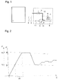
- a heating circuit controller integrated in the automatic firing unit 1 or an external heating circuit controller interacting with the automatic firing unit 1 determines the burner output required to cover the heat requirement.
- the automatic burner control 1 on the one hand continuously controls the fuel valve 3 with which the fuel conveyed through a fuel line 12, for example oil or gas, is fed to the combustion chamber, and on the other hand the speed controller 11.
- the size of the heat demand signal thus determines the degree of opening of the fuel valve 3 and the conveyed air volume flow V L.
- an asynchronous motor is provided as the motor.
- the speed controller 11 is thus a frequency converter.
- the air volume flow V L delivered at a specific speed of the blower motor 10 depends, among other things, on the flow resistance of the air duct 4, the combustion chamber and the exhaust gas fireplace.
- the first air pressure switch 6 is set such that it switches to the ON position when the pressure in the air duct 4 exceeds a predetermined minimum pressure p 1 .
- the second air pressure switch 7 switches to the ON position when the pressure in the air duct 4 reaches a value p 2 which corresponds to the conveyed air volume flow V L at full load.
- the relative speed N r1 at which the first air pressure switch 6 switches is assigned, for example, the value 0 percent, and the relative speed N r2 at which the second air pressure switch 7 switches is assigned the value 100 percent.
- the forced draft burner 2 first runs through an actual start-up program, in the course of which the burner control unit 1 adjusts the speed of the blower motor 10 such that the air pressure in the air duct 4 is just sufficient for the first air pressure switch 6 to be switched on and to remain on.
- the relative rotational speed N r, x is transmitted over the unit 1 the command to the speed controller 11, the rotational speed with the rate .DELTA.N to t x increase over time.
- the speed of the motor 10 For the regulator operation of the fan burner 2 following the start-up, it is advantageous to change the speed of the motor 10 relatively slowly, since the heat control often requires only small changes.
- the commissioning program begins with a flushing of the combustion chamber.
- the speed of the air blower 5 is increased as quickly as possible to the maximum speed corresponding to the full load.
- the calibration of the actual rate of change .DELTA.N r is, therefore takes place with a relatively small target change rate .DELTA.N should, therefore the air flow rate is possible in the controller operation, a precise control, while the start-up of the fan burner 2 takes place with the greatest possible desired rate of change.
- the automatic burner control unit 1 is repeated periodically, for example every 20th start-up, the calibration of the actual change rate ⁇ N r is repeated and a plausibility test is also carried out to determine whether the new actual change rate ⁇ N r is within predetermined tolerance values of the old actual - Rate of change corresponds. If the deviation is too great, there could be a break in the rigid coupling between the motor 10 and the air blower 5. In this case, the automatic burner control unit 1 performs a safety shutdown.
- the recalibration can take place, for example, after a predetermined number of control commands.
- the recalibration can also be carried out whenever one of the air pressure switches 6, 7 is started up anyway.
- the recalibration can also be provided if the air pressure switches 6, 7 have not been started for a predetermined period of time.
- the automatic burner control 1 therefore causes the speed N of the motor 10 to either be increased until the second air pressure switch 7 turns on, or is decreased until the first air pressure switch 6 turns off and then compares whether the time required for this with the time calculated according to equation (2) does not match , the value N r1 or N r2 being used for N r, y .
- the nearby air pressure switch 6, 7 is advantageously approached.
- the actual value of the change rate ⁇ N r, ist can be corrected.
- the rate of change ⁇ N r can either be redetermined in accordance with the method according to the invention, or the fan burner 2 can be switched off safely.
- FIG. 2 shows a possible course of the air pressure p in the air duct 4 (FIG. 1) or the speed N of the motor 10 of the air fan 5.
- the automatic burner control unit 1 transmits the command to the speed controller 11, the speed of the motor 10 at the rate ⁇ N should increase.
- the automatic burner control unit 1 starts the time measurement to determine the time period ⁇ t. The time measurement is stopped as soon as the second air pressure switch 7 switches on because the predetermined pressure p 2 in the air duct 4 has been reached.
- the automatic firing device 1 transmits to the speed controller 11 the command not to increase the speed of the motor 10 any further.
- the burner control now calculates the actual value of the rate ⁇ N ist according to equation (3).
- the air duct 4 and the combustion chamber are then thoroughly flushed with air.
- the conveyed air volume flow is then reduced again to a value that generates the minimum pressure p 1 , for example.
- any air volume flows can now be set according to equation (2).
- the invention can also be used if only the air pressure switch 7 is present, which switches on when the air pressure p reaches a predetermined maximum value p 2 .
- the automatic heating system 1 determines the rate .DELTA.N is by measuring the time required for the engine 10 to start up from standstill and reach the rotation speed N 2, in which the air pressure switch 7 reports that the pressure p 2 is reached.
- Certain speed controllers provide a digital or analog signal that indicates the current speed.
- the analog signal is e.g. available as 0 - 10 volt signal, with 0 V standstill and 10 V the maximum Designate speed.
- Speed can be queried as a digital variable. With such speed controllers, it is appropriate that the Fire machine after a command to change the speed that reported by the speed controller Signal about the current Drebiere analyzed and processed. Provided, that the reported signal meets the safety requirements can be used directly Monitoring and, if necessary, correction of the speed can be used.
Landscapes
- Engineering & Computer Science (AREA)
- Chemical & Material Sciences (AREA)
- Combustion & Propulsion (AREA)
- Mechanical Engineering (AREA)
- General Engineering & Computer Science (AREA)
- Regulation And Control Of Combustion (AREA)
Abstract
Description
- Fig. 1
- einen von einem Feuerungsautomaten gesteuerten Gebläsebrenner, und
- Fig. 2
- ein Diagramm.
Claims (6)
- Steuereinrichtung, insbesondere Feuerungsautomat (1), für einen Gebläsebrenner (2) mit einem Luftgebläse (5), wobei ein Drehzahlsteller (11) die Drehzahl des Motors (10) des Luftgebläses (5) steuert, und wobei die Steuereinrichtung (1) einen Inbetriebsetzungsvorgang und einen fortlaufenden Betrieb des Gebläsebrenners (2) steuert und überwacht, dadurch gekennzeichnet,
dass ein erster und ein zweiter Luftdruckschalter (6, 7) vorhanden ist, wobei der erste Luftdruckschalter (6) anspricht, wenn das Luftgebläse (5) einen ersten Luftdruck p1 erzeugt und wobei der zweite Luftdruckschalter (7) anspricht, wenn das Luftgebläse (5) einen zweiten Luftdruck p2 erzeugt, dass die Steuereinrichtung (1) bei jeder oder bei gewissen Inbetriebsetzungendass die Steuereinrichtung (1) eingerichtet ist, im Normalbetrieb am Motor (10) eine beliebige Drehzahl einzustellen, indem sie den Drehzahlsteller (11) anweist, die Drehzahl N mit der vorbestimmten Soll-Änderungsrate ΔNsoll während einer entsprechend der Ist-Änderungsrate ΔNr,ist berechneten Zeitspanne t1 zu ändern.a) den Drehzahlsteller (11) anweist, die Drehzahl N des Motors (10) mit einer vorbestimmten Soll-Änderungsrate ΔNsoll zu erhöhen,b) die Zeitspanne Δt ermittelt, die zwischen dem Ansprechen des ersten und des zweiten Luftdruckschalters (6, 7) verstreicht, undc) eine Ist-Änderungsrate ΔNr,ist berechnet, und - Steuereinrichtung, insbesondere Feuerungsautomat (1), für einen Gebläsebrenner (2) mit einem Luftgebläse (5), wobei ein Drehzahlsteller (11) die Drehzahl des Motors (10) des Luftgebläses (5) steuert, und wobei die Steuereinrichtung (1) einen Inbetriebsetzungsvorgang und einen fortlaufenden Betrieb des Gebläsebrenners (2) steuert und überwacht, dadurch gekennzeichnet,
dass ein Luftdruckschalter (7) vorhanden ist, der anspricht, wenn das Luftgebläse (5) einen maximalen Luftdruck p2 erzeugt, dass die Steuereinrichtung (1) bei jeder oder einer gewissen Inbetriebsetzungdass die Steuereinrichtung (1) eingerichtet ist, im Normalbetrieb am Motor (10) eine beliebige Drehzahl einzustellen, indem sie den Drehzahlsteller (11) anweist, die Drehzahl N mit der vorbestimmten Soll-Änderungsrate ΔNsoll während einer entsprechend der Ist-Änderungsrate ΔNr,ist berechneten Zeitspanne t1 zu ändern.a) den Drehzahlsteller (11) anweist, die Drehzahl N des Motors (10) aus dem Stillstand mit einer vorbestimmten Soll-Änderungsrate ΔNsoll erhöhen,b) die Zeitspanne Δt ermittelt, die zwischen dem Anlaufen des Motors (10) und dem Ansprechen des Luftdruckschalters (6) verstreicht, undc) eine Ist-Änderungsrate ΔNr,ist berechnet, und - Steuereinrichtung nach Anspruch 1 oder 2, dadurch gekennzeichnet, dass sie zur Steuerung eines für einen Wechselstrommotor ausgelegten Drehzahlstellers (11), insbesondere eines Frequenzumrichters, ausgelegt ist.
- Steuereinrichtung nach Anspruch 1 oder 2, dadurch gekennzeichnet, dass sie zur Steuerung eines für einen Gleichstrommotor ausgelegten Drehzahlstellers (11) ausgelegt ist.
- Steuereinrichtung nach einem der Ansprüche 1 bis 4, dadurch gekennzeichnet, dass sie im Normalbetrieb des Gebläsebrenners (2) Nachkalibrierungen der Ist-Rate ΔNist durchführt.
- Steuereinrichtung nach einem der Ansprüche 1 bis 5, dadurch gekennzeichnet, dass die berechnete Zeitspanne t1 um einen die Trägheit des Systems Motor (10) und Luftgebläse (5) berücksichtigenden Wert τ erhöht oder erniedrigt wird.
Priority Applications (2)
| Application Number | Priority Date | Filing Date | Title |
|---|---|---|---|
| EP97111687A EP0890790B1 (de) | 1997-07-08 | 1997-07-08 | Steuereinrichtung, insbesondere Feuerungsautomat, für einen Gebläsebrenner |
| DE59706767T DE59706767D1 (de) | 1997-07-08 | 1997-07-08 | Steuereinrichtung, insbesondere Feuerungsautomat, für einen Gebläsebrenner |
Applications Claiming Priority (1)
| Application Number | Priority Date | Filing Date | Title |
|---|---|---|---|
| EP97111687A EP0890790B1 (de) | 1997-07-08 | 1997-07-08 | Steuereinrichtung, insbesondere Feuerungsautomat, für einen Gebläsebrenner |
Publications (2)
| Publication Number | Publication Date |
|---|---|
| EP0890790A1 true EP0890790A1 (de) | 1999-01-13 |
| EP0890790B1 EP0890790B1 (de) | 2002-03-27 |
Family
ID=8227039
Family Applications (1)
| Application Number | Title | Priority Date | Filing Date |
|---|---|---|---|
| EP97111687A Expired - Lifetime EP0890790B1 (de) | 1997-07-08 | 1997-07-08 | Steuereinrichtung, insbesondere Feuerungsautomat, für einen Gebläsebrenner |
Country Status (2)
| Country | Link |
|---|---|
| EP (1) | EP0890790B1 (de) |
| DE (1) | DE59706767D1 (de) |
Cited By (3)
| Publication number | Priority date | Publication date | Assignee | Title |
|---|---|---|---|---|
| EP1717514A1 (de) * | 2005-04-29 | 2006-11-02 | Alde International Systems AB | Gasbrennervorrichtung sowie Start- und Betriebsverfahren dafür |
| ITBO20100440A1 (it) * | 2010-07-12 | 2012-01-13 | Baltur S P A | Sistema di controllo di un bruciatore ad aria soffiata |
| US20140023976A1 (en) * | 2008-05-27 | 2014-01-23 | Honeywell International, Inc. | Combustion blower control for modulating furnace |
Citations (7)
| Publication number | Priority date | Publication date | Assignee | Title |
|---|---|---|---|---|
| US4688547A (en) * | 1986-07-25 | 1987-08-25 | Carrier Corporation | Method for providing variable output gas-fired furnace with a constant temperature rise and efficiency |
| US4860231A (en) * | 1985-12-16 | 1989-08-22 | Carrier Corporation | Calibration technique for variable speed motors |
| JPH03291411A (ja) * | 1990-04-09 | 1991-12-20 | Matsushita Electric Ind Co Ltd | 燃焼装置 |
| EP0567060A1 (de) * | 1992-04-21 | 1993-10-27 | Joh. Vaillant GmbH u. Co. | Verfahren zur Steuerung eines Gas-Gebläsebrenners |
| EP0612960A1 (de) * | 1993-02-26 | 1994-08-31 | General Electric Company | Luftströmungsregelung mit induziertem Zug |
| EP0614048A1 (de) | 1993-03-05 | 1994-09-07 | Landis & Gyr Technology Innovation AG | Einrichtung mit einem Feuerungsautomaten |
| DE4410735A1 (de) | 1994-03-14 | 1995-09-21 | Landis & Gyr Business Support | Einrichtung mit einem Feuerungsautomaten |
-
1997
- 1997-07-08 DE DE59706767T patent/DE59706767D1/de not_active Expired - Fee Related
- 1997-07-08 EP EP97111687A patent/EP0890790B1/de not_active Expired - Lifetime
Patent Citations (7)
| Publication number | Priority date | Publication date | Assignee | Title |
|---|---|---|---|---|
| US4860231A (en) * | 1985-12-16 | 1989-08-22 | Carrier Corporation | Calibration technique for variable speed motors |
| US4688547A (en) * | 1986-07-25 | 1987-08-25 | Carrier Corporation | Method for providing variable output gas-fired furnace with a constant temperature rise and efficiency |
| JPH03291411A (ja) * | 1990-04-09 | 1991-12-20 | Matsushita Electric Ind Co Ltd | 燃焼装置 |
| EP0567060A1 (de) * | 1992-04-21 | 1993-10-27 | Joh. Vaillant GmbH u. Co. | Verfahren zur Steuerung eines Gas-Gebläsebrenners |
| EP0612960A1 (de) * | 1993-02-26 | 1994-08-31 | General Electric Company | Luftströmungsregelung mit induziertem Zug |
| EP0614048A1 (de) | 1993-03-05 | 1994-09-07 | Landis & Gyr Technology Innovation AG | Einrichtung mit einem Feuerungsautomaten |
| DE4410735A1 (de) | 1994-03-14 | 1995-09-21 | Landis & Gyr Business Support | Einrichtung mit einem Feuerungsautomaten |
Non-Patent Citations (2)
| Title |
|---|
| article LANDIS & GYR: "FEUREUNGSAUTOMATEN FUER OEL UND GASBRENNER" |
| PATENT ABSTRACTS OF JAPAN vol. 016, no. 129 (M - 1228) 2 April 1992 (1992-04-02) * |
Cited By (4)
| Publication number | Priority date | Publication date | Assignee | Title |
|---|---|---|---|---|
| EP1717514A1 (de) * | 2005-04-29 | 2006-11-02 | Alde International Systems AB | Gasbrennervorrichtung sowie Start- und Betriebsverfahren dafür |
| US20140023976A1 (en) * | 2008-05-27 | 2014-01-23 | Honeywell International, Inc. | Combustion blower control for modulating furnace |
| US10094593B2 (en) * | 2008-05-27 | 2018-10-09 | Honeywell International Inc. | Combustion blower control for modulating furnace |
| ITBO20100440A1 (it) * | 2010-07-12 | 2012-01-13 | Baltur S P A | Sistema di controllo di un bruciatore ad aria soffiata |
Also Published As
| Publication number | Publication date |
|---|---|
| EP0890790B1 (de) | 2002-03-27 |
| DE59706767D1 (de) | 2002-05-02 |
Similar Documents
| Publication | Publication Date | Title |
|---|---|---|
| EP2594848B1 (de) | Verfahren zur Steuerung einer Feuerungseinrichtung und Feuerungseinrichtung | |
| DE3707259C2 (de) | Brennervorrichtung | |
| EP0614046A1 (de) | Steuer - und Regeleinrichtung für Gas- Feuerungsautomaten von Heizungsanlagen | |
| DE3888327T2 (de) | Brennstoffbrennereinrichtung und ein Kontrollverfahren. | |
| EP0770824A2 (de) | Verfahren und Schaltung zur Regelung eines Gasbrenners | |
| DE3638410C2 (de) | ||
| EP3596391B1 (de) | Verfahren zur regelung eines brenngasbetriebenen heizgerätes | |
| EP3707433A1 (de) | Verfahren zur regelung eines brenngasbetriebenen heizgeräts | |
| WO1998020281A1 (de) | Druckzerstäuberbrenner für ein motorunabhängiges fahrzeugheizgerät | |
| EP3683500A1 (de) | Verfahren zur regelung eines gasgemisches unter nutzung eines gassensors und eines gasgemischsensors | |
| EP1186831A1 (de) | Regeleinrichtung für einen luftzahlgeregelten Brenner | |
| EP0614047B1 (de) | Elektronische Steuer-und Regeleinrichtung für Gasbrenner von Heizungsanlagen | |
| DE19627857C2 (de) | Verfahren zum Betrieb eines Gasgebläsebrenners | |
| EP0615095B1 (de) | Brennerregler | |
| EP0890790B1 (de) | Steuereinrichtung, insbesondere Feuerungsautomat, für einen Gebläsebrenner | |
| DE69808646T2 (de) | Ölbrenneranlage | |
| EP0339135A1 (de) | Verbundsteuereinrichtung für einen Brenner | |
| EP3680553B1 (de) | Verfahren zum regeln des verbrennungsluftverhältnisses am brenner eines heizgerätes | |
| DE4334625A1 (de) | Verfahren zum Konstanthalten der Leistung eines Wassererwärmers | |
| EP0614051B1 (de) | Feuerungsautomat | |
| EP1650502A2 (de) | Verfahren und Einrichtung zur Kalibrierung eines Heizwertgerätes | |
| EP4230911A1 (de) | Verfahren zur inbetriebnahme eines heizgerätes, computerprogramm, regel- und steuergerät, heizgerät und verwendung eines parameters | |
| EP0614048A1 (de) | Einrichtung mit einem Feuerungsautomaten | |
| DE102004063992B4 (de) | Verfahren zur Steuerung einer Feuerungseinrichtung und Feuerungseinrichtung | |
| AT505064B1 (de) | Regelung des brenngas-luft-gemisches über die brenner- oder flammentemperatur eines heizgerätes |
Legal Events
| Date | Code | Title | Description |
|---|---|---|---|
| PUAI | Public reference made under article 153(3) epc to a published international application that has entered the european phase |
Free format text: ORIGINAL CODE: 0009012 |
|
| AK | Designated contracting states |
Kind code of ref document: A1 Designated state(s): CH DE FR GB IT LI NL |
|
| AX | Request for extension of the european patent |
Free format text: AL;LT;LV;RO;SI |
|
| 17P | Request for examination filed |
Effective date: 19990713 |
|
| AKX | Designation fees paid |
Free format text: CH DE FR GB IT LI NL |
|
| RAP1 | Party data changed (applicant data changed or rights of an application transferred) |
Owner name: SIEMENS BUILDING TECHNOLOGIES AG |
|
| 17Q | First examination report despatched |
Effective date: 20000707 |
|
| GRAG | Despatch of communication of intention to grant |
Free format text: ORIGINAL CODE: EPIDOS AGRA |
|
| GRAG | Despatch of communication of intention to grant |
Free format text: ORIGINAL CODE: EPIDOS AGRA |
|
| GRAH | Despatch of communication of intention to grant a patent |
Free format text: ORIGINAL CODE: EPIDOS IGRA |
|
| GRAH | Despatch of communication of intention to grant a patent |
Free format text: ORIGINAL CODE: EPIDOS IGRA |
|
| REG | Reference to a national code |
Ref country code: GB Ref legal event code: IF02 |
|
| GRAA | (expected) grant |
Free format text: ORIGINAL CODE: 0009210 |
|
| AK | Designated contracting states |
Kind code of ref document: B1 Designated state(s): CH DE FR GB IT LI NL |
|
| PG25 | Lapsed in a contracting state [announced via postgrant information from national office to epo] |
Ref country code: GB Free format text: LAPSE BECAUSE OF FAILURE TO SUBMIT A TRANSLATION OF THE DESCRIPTION OR TO PAY THE FEE WITHIN THE PRESCRIBED TIME-LIMIT Effective date: 20020327 Ref country code: FR Free format text: LAPSE BECAUSE OF FAILURE TO SUBMIT A TRANSLATION OF THE DESCRIPTION OR TO PAY THE FEE WITHIN THE PRESCRIBED TIME-LIMIT Effective date: 20020327 |
|
| REG | Reference to a national code |
Ref country code: CH Ref legal event code: EP |
|
| REF | Corresponds to: |
Ref document number: 59706767 Country of ref document: DE Date of ref document: 20020502 |
|
| GBV | Gb: ep patent (uk) treated as always having been void in accordance with gb section 77(7)/1977 [no translation filed] |
Effective date: 20020327 |
|
| EN | Fr: translation not filed | ||
| PLBE | No opposition filed within time limit |
Free format text: ORIGINAL CODE: 0009261 |
|
| STAA | Information on the status of an ep patent application or granted ep patent |
Free format text: STATUS: NO OPPOSITION FILED WITHIN TIME LIMIT |
|
| 26N | No opposition filed |
Effective date: 20021230 |
|
| PGFP | Annual fee paid to national office [announced via postgrant information from national office to epo] |
Ref country code: DE Payment date: 20050922 Year of fee payment: 9 |
|
| PGFP | Annual fee paid to national office [announced via postgrant information from national office to epo] |
Ref country code: CH Payment date: 20051013 Year of fee payment: 9 |
|
| PGFP | Annual fee paid to national office [announced via postgrant information from national office to epo] |
Ref country code: NL Payment date: 20060711 Year of fee payment: 10 |
|
| PG25 | Lapsed in a contracting state [announced via postgrant information from national office to epo] |
Ref country code: LI Free format text: LAPSE BECAUSE OF NON-PAYMENT OF DUE FEES Effective date: 20060731 Ref country code: CH Free format text: LAPSE BECAUSE OF NON-PAYMENT OF DUE FEES Effective date: 20060731 |
|
| PGFP | Annual fee paid to national office [announced via postgrant information from national office to epo] |
Ref country code: IT Payment date: 20060731 Year of fee payment: 10 |
|
| PG25 | Lapsed in a contracting state [announced via postgrant information from national office to epo] |
Ref country code: DE Free format text: LAPSE BECAUSE OF NON-PAYMENT OF DUE FEES Effective date: 20070201 |
|
| REG | Reference to a national code |
Ref country code: CH Ref legal event code: PL |
|
| NLV4 | Nl: lapsed or anulled due to non-payment of the annual fee |
Effective date: 20080201 |
|
| PG25 | Lapsed in a contracting state [announced via postgrant information from national office to epo] |
Ref country code: NL Free format text: LAPSE BECAUSE OF NON-PAYMENT OF DUE FEES Effective date: 20080201 |
|
| PG25 | Lapsed in a contracting state [announced via postgrant information from national office to epo] |
Ref country code: IT Free format text: LAPSE BECAUSE OF NON-PAYMENT OF DUE FEES Effective date: 20070708 |