EP0890802A2 - Dispositif d'amenée et d'évacuation d'air avec récupération de chaleur régénérable - Google Patents
Dispositif d'amenée et d'évacuation d'air avec récupération de chaleur régénérable Download PDFInfo
- Publication number
- EP0890802A2 EP0890802A2 EP98109946A EP98109946A EP0890802A2 EP 0890802 A2 EP0890802 A2 EP 0890802A2 EP 98109946 A EP98109946 A EP 98109946A EP 98109946 A EP98109946 A EP 98109946A EP 0890802 A2 EP0890802 A2 EP 0890802A2
- Authority
- EP
- European Patent Office
- Prior art keywords
- heat storage
- fan
- housing
- ventilation system
- storage unit
- Prior art date
- Legal status (The legal status is an assumption and is not a legal conclusion. Google has not performed a legal analysis and makes no representation as to the accuracy of the status listed.)
- Granted
Links
Images

Classifications
-
- F—MECHANICAL ENGINEERING; LIGHTING; HEATING; WEAPONS; BLASTING
- F24—HEATING; RANGES; VENTILATING
- F24F—AIR-CONDITIONING; AIR-HUMIDIFICATION; VENTILATION; USE OF AIR CURRENTS FOR SCREENING
- F24F12/00—Use of energy recovery systems in air conditioning, ventilation or screening
- F24F12/001—Use of energy recovery systems in air conditioning, ventilation or screening with heat-exchange between supplied and exhausted air
- F24F12/002—Use of energy recovery systems in air conditioning, ventilation or screening with heat-exchange between supplied and exhausted air using an intermediate heat-transfer fluid
-
- F—MECHANICAL ENGINEERING; LIGHTING; HEATING; WEAPONS; BLASTING
- F24—HEATING; RANGES; VENTILATING
- F24F—AIR-CONDITIONING; AIR-HUMIDIFICATION; VENTILATION; USE OF AIR CURRENTS FOR SCREENING
- F24F12/00—Use of energy recovery systems in air conditioning, ventilation or screening
- F24F12/001—Use of energy recovery systems in air conditioning, ventilation or screening with heat-exchange between supplied and exhausted air
- F24F12/006—Use of energy recovery systems in air conditioning, ventilation or screening with heat-exchange between supplied and exhausted air using an air-to-air heat exchanger
-
- F—MECHANICAL ENGINEERING; LIGHTING; HEATING; WEAPONS; BLASTING
- F24—HEATING; RANGES; VENTILATING
- F24F—AIR-CONDITIONING; AIR-HUMIDIFICATION; VENTILATION; USE OF AIR CURRENTS FOR SCREENING
- F24F12/00—Use of energy recovery systems in air conditioning, ventilation or screening
- F24F12/001—Use of energy recovery systems in air conditioning, ventilation or screening with heat-exchange between supplied and exhausted air
- F24F2012/008—Use of energy recovery systems in air conditioning, ventilation or screening with heat-exchange between supplied and exhausted air cyclic routing supply and exhaust air
-
- Y—GENERAL TAGGING OF NEW TECHNOLOGICAL DEVELOPMENTS; GENERAL TAGGING OF CROSS-SECTIONAL TECHNOLOGIES SPANNING OVER SEVERAL SECTIONS OF THE IPC; TECHNICAL SUBJECTS COVERED BY FORMER USPC CROSS-REFERENCE ART COLLECTIONS [XRACs] AND DIGESTS
- Y02—TECHNOLOGIES OR APPLICATIONS FOR MITIGATION OR ADAPTATION AGAINST CLIMATE CHANGE
- Y02B—CLIMATE CHANGE MITIGATION TECHNOLOGIES RELATED TO BUILDINGS, e.g. HOUSING, HOUSE APPLIANCES OR RELATED END-USER APPLICATIONS
- Y02B30/00—Energy efficient heating, ventilation or air conditioning [HVAC]
- Y02B30/56—Heat recovery units
Definitions
- the invention relates to a ventilation system with regenerative Heat recovery, comprising an elongated, inner and outer loading and Venting housing, in the alternating driven fan units for conveying substantially axially using the housing in opposite directions same flow path and one of heat storage unit through which the generated air flows flow and temporarily storing the heat of the heat storage unit in one direction flowing air flow and for dispensing the same to which the heat storage unit in the opposite direction flowing air flow are arranged.
- Such a ventilation system is known from DE-GM 77 09 149.7.
- Such ventilation systems are used for ventilation used by rooms, especially in cold seasons at a Room air exchange the heat in such a room as far as possible in the room and not unnecessarily to the outside to deliver. Conversely, such a system works with air-conditioning Clear in hot seasons.
- the ventilation system described in the document mentioned consists of an elongated housing in which a heat storage unit is arranged. At each inlet and outlet end of the heat storage unit an axial fan is arranged, the conveying direction is directed towards the heat storage unit. One end of the case the ventilation system opens into a room; the other End communicates with the outside air. In winter there is room loading and Venting in such a way that the inner axial fan is initially driven and a ventilation air flow from the room through the heat storage unit through to the outside. The in the vent airflow contained heat is released to the heat storage unit. After a predetermined time interval, this axial fan is switched off and the other axial fan to promote the ventilation air flow driven. The entering cooler fresh air is then when flowing through the heat storage unit heats up and thus enters the heated Interior of the room.
- a further ventilation system is known from DE 30 06 318 C2, which, however, in contrast to the ventilation system according to the DE-GM 77 09 149.7 not based on the principle of regenerative heat recovery but according to the principle of recuperative heat recovery is working.
- the operation of such a system consists of one Provision of two funded simultaneously and separately Air flows through one or more heat exchanger elements be so that the heat contained in the ventilation air flow to the Ventilation airflow is transmitted.
- standard radial fans are used. Because of the provision two intersecting flow channels and the necessarily Radial fans to be arranged parallel to one another require one Ventilation system more width or installation depth with the same Performance or with the same efficiency. Therefore, one is on the principle the recuperative heat recovery system does not work optimally suitable for use in very compact systems. It is proved that according to the regenerative principle of heat recovery working ventilation systems not only by one distinguish better efficiency, but that with these systems condensation is also prevented.
- DE 41 34 429 C1 is a cooling device for electronic cabinets in one particularly flat design known.
- This device works according to the Principle of a two-circuit cooling system in which the heat to be dissipated one airflow through a heat exchanger to a cooler airflow is transmitted.
- the airflow to be cooled is based on the two-circuit principle sucked out of the electronics cabinet and after its cooling again blown into the electronics cabinet.
- the heat dissipator Airflow is sucked in by the environment and after it Warming released again to the environment.
- centrifugal fans are used, which simultaneously operate the Air flows in the respective, separate flow channels in promote opposite directions.
- This device is for ventilation of rooms however not suitable.
- the invention lies hence the task of a ventilation system that according to working on the principle of regenerative heat recovery, which are particularly suitable for use in narrow dimensions Compact systems are suitable.
- each fan unit from a radial fan wheel and the conveying air to the Heat storage unit directing conveyor housing with an outlet nozzle which fan unit has the radial distance of the radial fan wheel to its conveyor housing and the opening width of the outlet nozzle are designed so that each fan unit in the non-driven State of that supported by the other fan unit Air flow can be flowed through, so that the flow path of the conveying air in in both directions through the fan units, by the conveying air through the operation of the one fan unit actively promoted and this fan unit when operating the other fan unit flowed through by the air conveyed in the reverse direction becomes.
- radial fans as fan units with one each Radial fan wheel, which in a predetermined, sufficiently large radial distance from the conveyor housing assigned to it, ensures that such a fan unit not only during operation build up a higher delivery pressure compared to axial fans but that this fan unit is different from the other Fan unit generated air flow against the own direction of delivery can be flowed through without this fan unit essential Represents flow obstacle.
- the outlet nozzle is also corresponding of each fan unit.
- one fan unit each at each inlet and outlet end of the heat storage unit is arranged.
- the fan units adjacent to each other at the inflow or outflow end the heat storage unit are arranged.
- the individual elements of the ventilation system can be built in modules be integrated in a housing.
- the fan units with their outlet connections adjacent to one another or in a common one Conveyor housing are arranged.
- the fan units are at each end of the heat storage unit provided, it may be appropriate that the fan units each in the area of the end sections of the housing of the ventilation system are arranged so that these housing sections simultaneously represent the conveyor housing.
- the Depth of such a system essentially the width of a radial fan wheel correspond, so that such a design especially for extremely compact systems is an advantage. It is also advantageous that none own conveyor housing is provided, so that the manufacturing costs accordingly such a ventilation system are reduced.
- a separate conveyor housing can be provided, which in the direction of the heat storage unit has a funnel-shaped widening Has outlet connection. This ensures that the entire Conveying air from the other fan unit in operation in this fan unit is introduced, flows through it and the loading and Ventilation system through the suction opening of this fan unit again leaves.
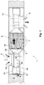
- FIG. 1 shows a ventilation system 1.
- the ventilation system 1 is inserted into the outer wall 2 of a room.
- the loading and Ventilation system 1 comprises an elongated, rectangular in cross section Housing 3, in which an outer ventilation opening 4 and a inner ventilation opening 5 are introduced.
- the inner loading and Vent opening 5 opens into the interior of the room; the outer ventilation opening 4 opens out.
- a heat storage unit 6 is arranged approximately centrally in the housing 3, which in turn consist of several made up of individual heat storage plates Heat storage packages 7 exists.
- the heat storage unit 6 is in the longitudinal direction of the ventilation system 1 according to arrows 8, 9 flowable. It is therefore possible between the inner ventilation opening 5 and the outer ventilation opening 4 a To generate heat storage unit 6 flowing air flow and vice versa.
- the heat storage unit 6 is on both sides one fan unit 10, 11 each.
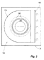
- the fan unit 10 comprises an electric motor driven radial fan wheel 12 and a conveyor housing 13.
- the radial fan wheel 12 borders with its suction opening 14 to the outer ventilation opening 4. It is provided that the Ventilation opening 4 has a connecting piece 15, so the suction opening 14 of the radial fan wheel 12 directly to the patient Vent opening 4 borders. A small gap between the radial fan wheel 12 and the connecting piece 15 is necessary so that the radial fan wheel 12 can rotate freely.
- the conveyor housing 13 surrounds the radial fan wheel 12 and points at it to the heat storage unit 6 facing opening side a funnel-shaped trained outlet connection 16.
- the opening width of the outlet nozzle 16 corresponds essentially to the width of the heat storage unit 6 and thus the clear depth of the housing 3; the amount of Outlet socket corresponds essentially to the height of the heat storage unit and thus the clear height of the housing 3.
- the outlet nozzle 16 borders on the heat storage unit 6 and its configuration covers essentially all of its outflow end face.
- the conveyor housing 13 points with respect of the radial fan wheel 12 to a certain radial distance 17. Of the Distance corresponds to that in the embodiment shown in FIG 0.4 times the diameter of the radial fan wheel 12. Furthermore, provided that the individual blades 18 a certain distance from each other.
- the configuration of the blades 18 and the maintained radial distance 17 between the radial fan wheel 12 and the conveyor housing 13 serves to let an air flow through the arrow 8 when operating the fan unit 11 and thus in the motor Standstill of the fan unit 10.
- the conveying housing 13 represents only an insignificant flow obstacle for the air flow flowing through the fan unit 10 represents.
- the fan unit 10 When operating the ventilation system 1, the fan unit 10 to promote the ventilation air flow and the fan unit 11 to Promotion of the ventilation air flow provided.
- the fan units 10, 11 are driven alternately for this purpose.
- the fan unit 11 In the venting mode the ventilation system 1, the fan unit 11 is in operation and promotes the ventilation air flow - indicated by the arrows 8 - that by the inner ventilation opening 5 in the suction opening of the Fan unit 11 assigned radial fan wheel enters and through this is promoted to act on the heat storage unit 6.
- After Flow through the heating unit 6, one in relation to the The interior air temperature is lower than the ventilation air flow 8 deprived of heat.
- the ventilation air flow occurs Flow through the heating unit 6 in the outlet connection 16 of the fan unit 10, flows through it and passes through the ventilation opening 4 outward unhindered.
- the fan unit 10 In such an operation the fan unit 10 is in the rest position, so that it is only passive is flowed through by the vent air flow. After switching the ventilation system 1 from its ventilation operation on their Ventilation mode, the fan unit 11 is switched off and the fan unit 10 turned on. The housing 3 of the ventilation system 1 is now indicated by the ventilation air flow - by the arrows 9 - flows in the opposite direction. The one entering from outside and thus relatively cool ventilation air flow takes in the heat storage unit 6 stored heat and then comes out heated the ventilation opening 5 into the interior of the room.
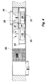
- FIG. 19 A further, simplified ventilation system 19 is shown in FIG.
- the ventilation system 19 is in accordance with the ventilation and Ventilation system 1 constructed, but does not have its own conveyor housing on. In this embodiment, the respective end portions of the Housing 3 the conveyor housing.
- the units contained in the housing 3 in FIGS. 1 and 3 - Heat storage unit 6 and fan units 10, 11 - are more appropriate Made as modules that are supported on guide rails.
- the individual units 6, 10, 11 can be used to dampen Vibrations caused by foam rubber inserts from each other.
- the inner one Ventilation opening 5 is designed so that this by a removable grille is formed inside. After removing it, the Fan unit 11 can be removed from the housing 3. Then is the heat storage unit 6 and then the fan unit 10 from the Pull-out housing 3.
- Such an embodiment has the advantage that with a small dimension opening - grille in the area of the inner loading and Vent 5 - accessed the individual modules used can be without the ventilation system over its entire Length must be opened. Especially when it comes to Repairs or when replacing individual modules is one of them Assembly system advantageous.
- the suction openings of the two fan units 20, 21 are through a Housing wall 27 and by a placed on the conveyor housing 25 Plate 28 separated from each other, the suction opening of the outer Fan unit 21, as described above, in the area of loading and Vent opening 26 of the housing is located and thus the other Suction opening is arranged within the housing.
- the flow path of the air flows is clearly determined, so that an air flow only through the two fan units 20, 21 can be promoted as this for the vent air flow through the filled Arrows and for the ventilation airflow through those shown only in outline Arrows is symbolized.
- Switching the operation of the described ventilation systems from a ventilation operation to a ventilation operation and vice versa can take place according to a predetermined time cycle.
- heat measuring sensors to the heat storage unit are connected, the respective temperature of the heat storage unit capture and forward to a control unit.
- Dependent on The temperature of the heat storage unit then takes place Switching from the venting mode to the ventilation mode, whereby this temperature is preselected so that another one in the venting mode sufficient heat transfer to the heat storage unit is possible.
- there is a switch from ventilation mode to ventilation mode when the heat storage unit stores a large part of it Has given off heat to the ventilation air flow, so that a further heating of the ventilation air flow no longer or only takes place subordinate.
Landscapes
- Engineering & Computer Science (AREA)
- Chemical & Material Sciences (AREA)
- Combustion & Propulsion (AREA)
- Mechanical Engineering (AREA)
- General Engineering & Computer Science (AREA)
- Ventilation (AREA)
- Structures Of Non-Positive Displacement Pumps (AREA)
- Central Heating Systems (AREA)
- External Artificial Organs (AREA)
- Motor Or Generator Cooling System (AREA)
Applications Claiming Priority (2)
| Application Number | Priority Date | Filing Date | Title |
|---|---|---|---|
| DE19730019 | 1997-07-12 | ||
| DE19730019A DE19730019C1 (de) | 1997-07-12 | 1997-07-12 | Be- und Entlüftungsanlage mit regenerativer Wärmerückgewinnung |
Publications (3)
| Publication Number | Publication Date |
|---|---|
| EP0890802A2 true EP0890802A2 (fr) | 1999-01-13 |
| EP0890802A3 EP0890802A3 (fr) | 2000-12-20 |
| EP0890802B1 EP0890802B1 (fr) | 2003-03-26 |
Family
ID=7835583
Family Applications (1)
| Application Number | Title | Priority Date | Filing Date |
|---|---|---|---|
| EP98109946A Expired - Lifetime EP0890802B1 (fr) | 1997-07-12 | 1998-05-30 | Dispositif d'amenée et d'évacuation d'air avec récupération de chaleur régénérable |
Country Status (5)
| Country | Link |
|---|---|
| EP (1) | EP0890802B1 (fr) |
| AT (1) | ATE235667T1 (fr) |
| DE (2) | DE19730019C1 (fr) |
| DK (1) | DK0890802T3 (fr) |
| ES (1) | ES2195225T3 (fr) |
Cited By (2)
| Publication number | Priority date | Publication date | Assignee | Title |
|---|---|---|---|---|
| DE102011080358A1 (de) * | 2011-08-03 | 2013-02-07 | LUNOS Lüftungstechnik GmbH für Raumluftsysteme | Einbauprofil |
| US10746422B2 (en) | 2011-08-03 | 2020-08-18 | Lunos Luftungstechnik Gmbh Fur Raumluftsysteme | Recessed profile |
Families Citing this family (1)
| Publication number | Priority date | Publication date | Assignee | Title |
|---|---|---|---|---|
| DE202014003368U1 (de) * | 2014-01-14 | 2014-07-23 | LUNOS Lüftungstechnik GmbH für Raumluftsysteme | Lüftungsgerät zur Innenraumbelüftung in Gebäuden |
Citations (3)
| Publication number | Priority date | Publication date | Assignee | Title |
|---|---|---|---|---|
| DE7709149U1 (de) | 1977-03-24 | 1977-08-11 | Keller, Guenter, 6741 Minfeld | Vorrichtung zur heizung und lueftung von haeusern und raeumen |
| DE3006318C2 (de) | 1980-02-20 | 1986-08-07 | MLL Maximal Lärmschutz-Lüftungen GmbH | Lüftungsvorrichtung |
| DE4134429C1 (en) | 1991-10-18 | 1993-03-11 | Schroff Gmbh, 7541 Straubenhardt, De | Heat sink device for electronic cabinet - uses counterflow heat exchanger with vertical flow channels for cooling air stream and ambient air. |
Family Cites Families (3)
| Publication number | Priority date | Publication date | Assignee | Title |
|---|---|---|---|---|
| NO154708C (no) * | 1984-06-28 | 1986-12-03 | Paul Tengesdal | Ventilasjonsapparat med varmegjenvinning. |
| US5230719A (en) * | 1990-05-15 | 1993-07-27 | Erling Berner | Dehumidification apparatus |
| DE4104423C2 (de) * | 1991-02-14 | 1994-10-13 | Erich Klawitter | Entlüftungs- und Belüftungsanlage mit einem Wärmespeicher |
-
1997
- 1997-07-12 DE DE19730019A patent/DE19730019C1/de not_active Expired - Fee Related
-
1998
- 1998-05-30 DE DE59807617T patent/DE59807617D1/de not_active Expired - Lifetime
- 1998-05-30 AT AT98109946T patent/ATE235667T1/de not_active IP Right Cessation
- 1998-05-30 ES ES98109946T patent/ES2195225T3/es not_active Expired - Lifetime
- 1998-05-30 DK DK98109946T patent/DK0890802T3/da active
- 1998-05-30 EP EP98109946A patent/EP0890802B1/fr not_active Expired - Lifetime
Patent Citations (3)
| Publication number | Priority date | Publication date | Assignee | Title |
|---|---|---|---|---|
| DE7709149U1 (de) | 1977-03-24 | 1977-08-11 | Keller, Guenter, 6741 Minfeld | Vorrichtung zur heizung und lueftung von haeusern und raeumen |
| DE3006318C2 (de) | 1980-02-20 | 1986-08-07 | MLL Maximal Lärmschutz-Lüftungen GmbH | Lüftungsvorrichtung |
| DE4134429C1 (en) | 1991-10-18 | 1993-03-11 | Schroff Gmbh, 7541 Straubenhardt, De | Heat sink device for electronic cabinet - uses counterflow heat exchanger with vertical flow channels for cooling air stream and ambient air. |
Cited By (2)
| Publication number | Priority date | Publication date | Assignee | Title |
|---|---|---|---|---|
| DE102011080358A1 (de) * | 2011-08-03 | 2013-02-07 | LUNOS Lüftungstechnik GmbH für Raumluftsysteme | Einbauprofil |
| US10746422B2 (en) | 2011-08-03 | 2020-08-18 | Lunos Luftungstechnik Gmbh Fur Raumluftsysteme | Recessed profile |
Also Published As
| Publication number | Publication date |
|---|---|
| DE19730019C1 (de) | 1999-01-07 |
| EP0890802A3 (fr) | 2000-12-20 |
| DE59807617D1 (de) | 2003-04-30 |
| EP0890802B1 (fr) | 2003-03-26 |
| ES2195225T3 (es) | 2003-12-01 |
| DK0890802T3 (da) | 2003-07-21 |
| ATE235667T1 (de) | 2003-04-15 |
Similar Documents
| Publication | Publication Date | Title |
|---|---|---|
| DE3930429A1 (de) | Klimaanlage fuer kraftfahrzeuge, insbesondere omnibusse | |
| CH617891A5 (fr) | ||
| EP2839724B1 (fr) | Appareil de refroidissement pour le refroidissement d'armoires électriques | |
| WO2011138079A1 (fr) | Boîtier en baie pour le logement d'une pluralité de composants en tiroir | |
| EP0890802B1 (fr) | Dispositif d'amenée et d'évacuation d'air avec récupération de chaleur régénérable | |
| EP0026443B1 (fr) | Dispositif pour évacuer la chaleur perdue de boîtiers d'appareillage électronique encastrés dans un bâti d'armoire | |
| DE19638535C2 (de) | Be- und Entlüftungsanlage mit Wärmerückgewinnung | |
| DE9301812U1 (de) | Entlüftungs- und Belüftungsanlage mit einem Wärmespeicher | |
| EP0664423A1 (fr) | Convecteur à ventilation forcée | |
| EP1475876B1 (fr) | Chargeur pour un bloc-batterie et dispositif constitué d'un chargeur et d'un bloc-batterie | |
| DE102011050323B3 (de) | Kühlvorrichtung zur Klimatisierung einer Datenverarbeitungsanlage | |
| EP4149775B1 (fr) | Système de climatisation | |
| DE1604240C3 (de) | Gerät zum Heizen und/oder Kühlen von Raumluft | |
| EP3048869B1 (fr) | Centre de calcul | |
| EP2665350B1 (fr) | Unité de ventilateur pour le refroidissement de modules, tels que des modules électriques/électroniques, des appareils et analogues | |
| WO2021228425A1 (fr) | Système de climatisation | |
| EP2201304B1 (fr) | Dispositif de stockage a atmosphère de stockage prédéfinie | |
| WO2021228424A1 (fr) | Système de climatisation | |
| DE10215596B4 (de) | Raum-Aufheizeinheit | |
| DE1246790B (de) | Anordnung von Kuehlern in Schienentriebfahrzeugen | |
| EP2339284B1 (fr) | Agencement de radiateur | |
| DE1904284A1 (de) | Luftumwaelzer fuer Klimaanlagen | |
| DE19949873A1 (de) | Elektrische Schaltanlage | |
| DE102008012200A1 (de) | Wärmetauscher | |
| DE2014584B2 (de) | Klimaprüfkammer |
Legal Events
| Date | Code | Title | Description |
|---|---|---|---|
| PUAI | Public reference made under article 153(3) epc to a published international application that has entered the european phase |
Free format text: ORIGINAL CODE: 0009012 |
|
| AK | Designated contracting states |
Kind code of ref document: A2 Designated state(s): AT BE CH DE DK ES FR GB IT LI NL SE |
|
| AX | Request for extension of the european patent |
Free format text: AL;LT;LV;MK;RO;SI |
|
| PUAL | Search report despatched |
Free format text: ORIGINAL CODE: 0009013 |
|
| AK | Designated contracting states |
Kind code of ref document: A3 Designated state(s): AT BE CH CY DE DK ES FI FR GB GR IE IT LI LU MC NL PT SE |
|
| AX | Request for extension of the european patent |
Free format text: AL;LT;LV;MK;RO;SI |
|
| 17P | Request for examination filed |
Effective date: 20001113 |
|
| AKX | Designation fees paid |
Free format text: AT BE CH DE DK ES FR GB IT LI NL SE |
|
| GRAH | Despatch of communication of intention to grant a patent |
Free format text: ORIGINAL CODE: EPIDOS IGRA |
|
| GRAH | Despatch of communication of intention to grant a patent |
Free format text: ORIGINAL CODE: EPIDOS IGRA |
|
| GRAA | (expected) grant |
Free format text: ORIGINAL CODE: 0009210 |
|
| AK | Designated contracting states |
Designated state(s): AT BE CH DE DK ES FR GB IT LI NL SE |
|
| REG | Reference to a national code |
Ref country code: GB Ref legal event code: FG4D Free format text: NOT ENGLISH |
|
| REG | Reference to a national code |
Ref country code: CH Ref legal event code: EP |
|
| REF | Corresponds to: |
Ref document number: 59807617 Country of ref document: DE Date of ref document: 20030430 Kind code of ref document: P |
|
| REG | Reference to a national code |
Ref country code: CH Ref legal event code: NV Representative=s name: OK PAT AG PATENTE MARKEN LIZENZEN |
|
| REG | Reference to a national code |
Ref country code: SE Ref legal event code: TRGR |
|
| REG | Reference to a national code |
Ref country code: DK Ref legal event code: T3 |
|
| GBT | Gb: translation of ep patent filed (gb section 77(6)(a)/1977) | ||
| ET | Fr: translation filed | ||
| PLBE | No opposition filed within time limit |
Free format text: ORIGINAL CODE: 0009261 |
|
| STAA | Information on the status of an ep patent application or granted ep patent |
Free format text: STATUS: NO OPPOSITION FILED WITHIN TIME LIMIT |
|
| 26N | No opposition filed |
Effective date: 20031230 |
|
| PGFP | Annual fee paid to national office [announced via postgrant information from national office to epo] |
Ref country code: GB Payment date: 20050505 Year of fee payment: 8 |
|
| PGFP | Annual fee paid to national office [announced via postgrant information from national office to epo] |
Ref country code: NL Payment date: 20050518 Year of fee payment: 8 |
|
| PGFP | Annual fee paid to national office [announced via postgrant information from national office to epo] |
Ref country code: FR Payment date: 20050519 Year of fee payment: 8 |
|
| PGFP | Annual fee paid to national office [announced via postgrant information from national office to epo] |
Ref country code: BE Payment date: 20050523 Year of fee payment: 8 |
|
| PGFP | Annual fee paid to national office [announced via postgrant information from national office to epo] |
Ref country code: CH Payment date: 20050524 Year of fee payment: 8 Ref country code: SE Payment date: 20050524 Year of fee payment: 8 |
|
| PGFP | Annual fee paid to national office [announced via postgrant information from national office to epo] |
Ref country code: DK Payment date: 20050525 Year of fee payment: 8 |
|
| PGFP | Annual fee paid to national office [announced via postgrant information from national office to epo] |
Ref country code: ES Payment date: 20050531 Year of fee payment: 8 |
|
| PG25 | Lapsed in a contracting state [announced via postgrant information from national office to epo] |
Ref country code: GB Free format text: LAPSE BECAUSE OF NON-PAYMENT OF DUE FEES Effective date: 20060530 |
|
| PG25 | Lapsed in a contracting state [announced via postgrant information from national office to epo] |
Ref country code: SE Free format text: LAPSE BECAUSE OF NON-PAYMENT OF DUE FEES Effective date: 20060531 Ref country code: LI Free format text: LAPSE BECAUSE OF NON-PAYMENT OF DUE FEES Effective date: 20060531 Ref country code: ES Free format text: LAPSE BECAUSE OF NON-PAYMENT OF DUE FEES Effective date: 20060531 Ref country code: DK Free format text: LAPSE BECAUSE OF NON-PAYMENT OF DUE FEES Effective date: 20060531 Ref country code: CH Free format text: LAPSE BECAUSE OF NON-PAYMENT OF DUE FEES Effective date: 20060531 Ref country code: BE Free format text: LAPSE BECAUSE OF NON-PAYMENT OF DUE FEES Effective date: 20060531 |
|
| PG25 | Lapsed in a contracting state [announced via postgrant information from national office to epo] |
Ref country code: NL Free format text: LAPSE BECAUSE OF NON-PAYMENT OF DUE FEES Effective date: 20061201 |
|
| REG | Reference to a national code |
Ref country code: CH Ref legal event code: PL Ref country code: DK Ref legal event code: EBP |
|
| EUG | Se: european patent has lapsed | ||
| GBPC | Gb: european patent ceased through non-payment of renewal fee |
Effective date: 20060530 |
|
| NLV4 | Nl: lapsed or anulled due to non-payment of the annual fee |
Effective date: 20061201 |
|
| REG | Reference to a national code |
Ref country code: FR Ref legal event code: ST Effective date: 20070131 |
|
| PGFP | Annual fee paid to national office [announced via postgrant information from national office to epo] |
Ref country code: AT Payment date: 20070523 Year of fee payment: 10 |
|
| REG | Reference to a national code |
Ref country code: ES Ref legal event code: FD2A Effective date: 20060531 |
|
| BERE | Be: lapsed |
Owner name: *DIELS MANFRED Effective date: 20060531 |
|
| PGFP | Annual fee paid to national office [announced via postgrant information from national office to epo] |
Ref country code: IT Payment date: 20070525 Year of fee payment: 10 |
|
| PG25 | Lapsed in a contracting state [announced via postgrant information from national office to epo] |
Ref country code: FR Free format text: LAPSE BECAUSE OF NON-PAYMENT OF DUE FEES Effective date: 20060531 |
|
| PG25 | Lapsed in a contracting state [announced via postgrant information from national office to epo] |
Ref country code: AT Free format text: LAPSE BECAUSE OF NON-PAYMENT OF DUE FEES Effective date: 20080530 |
|
| PG25 | Lapsed in a contracting state [announced via postgrant information from national office to epo] |
Ref country code: IT Free format text: LAPSE BECAUSE OF NON-PAYMENT OF DUE FEES Effective date: 20080530 |
|
| REG | Reference to a national code |
Ref country code: DE Ref legal event code: R082 Ref document number: 59807617 Country of ref document: DE Representative=s name: LUTHER RECHTSANWALTSGESELLSCHAFT MBH, DE |
|
| REG | Reference to a national code |
Ref legal event code: R082 Ref country code: DE Ref document number: 59807617 Country of ref document: DE Representative=s name: LUTHER RECHTSANWALTSGESELLSCHAFT MBH, DE Effective date: 20150421 Ref country code: DE Ref legal event code: R082 Ref document number: 59807617 Country of ref document: DE Representative=s name: PATENTANWAELTE SCHROETER & ALBRECHT, DE Effective date: 20150421 Ref country code: DE Ref legal event code: R081 Ref document number: 59807617 Country of ref document: DE Owner name: MDM DIELS GMBH, DE Free format text: FORMER OWNER: DIELS, MANFRED, 58540 MEINERZHAGEN, DE Effective date: 20150421 |
|
| PGFP | Annual fee paid to national office [announced via postgrant information from national office to epo] |
Ref country code: DE Payment date: 20150205 Year of fee payment: 18 |
|
| REG | Reference to a national code |
Ref legal event code: R082 Ref document number: 59807617 Ref country code: DE Country of ref document: DE Representative=s name: PATENTANWAELTE SCHROETER & ALBRECHT, DE |
|
| REG | Reference to a national code |
Ref country code: DE Ref legal event code: R082 Ref document number: 59807617 Country of ref document: DE |
|
| REG | Reference to a national code |
Ref country code: DE Ref legal event code: R119 Ref document number: 59807617 Country of ref document: DE |
|
| PG25 | Lapsed in a contracting state [announced via postgrant information from national office to epo] |
Ref country code: DE Free format text: LAPSE BECAUSE OF NON-PAYMENT OF DUE FEES Effective date: 20161201 |