EP0890837A2 - Testing apparatus for gas sensors - Google Patents
Testing apparatus for gas sensors Download PDFInfo
- Publication number
- EP0890837A2 EP0890837A2 EP98112911A EP98112911A EP0890837A2 EP 0890837 A2 EP0890837 A2 EP 0890837A2 EP 98112911 A EP98112911 A EP 98112911A EP 98112911 A EP98112911 A EP 98112911A EP 0890837 A2 EP0890837 A2 EP 0890837A2
- Authority
- EP
- European Patent Office
- Prior art keywords
- resistors
- gas
- sensor
- electrodes
- substrate
- Prior art date
- Legal status (The legal status is an assumption and is not a legal conclusion. Google has not performed a legal analysis and makes no representation as to the accuracy of the status listed.)
- Withdrawn
Links
Images

Classifications
-
- G—PHYSICS
- G01—MEASURING; TESTING
- G01N—INVESTIGATING OR ANALYSING MATERIALS BY DETERMINING THEIR CHEMICAL OR PHYSICAL PROPERTIES
- G01N27/00—Investigating or analysing materials by the use of electric, electrochemical, or magnetic means
- G01N27/26—Investigating or analysing materials by the use of electric, electrochemical, or magnetic means by investigating electrochemical variables; by using electrolysis or electrophoresis
- G01N27/403—Cells and electrode assemblies
- G01N27/404—Cells with anode, cathode and cell electrolyte on the same side of a permeable membrane which separates them from the sample fluid, e.g. Clark-type oxygen sensors
-
- G—PHYSICS
- G01—MEASURING; TESTING
- G01D—MEASURING NOT SPECIALLY ADAPTED FOR A SPECIFIC VARIABLE; ARRANGEMENTS FOR MEASURING TWO OR MORE VARIABLES NOT COVERED IN A SINGLE OTHER SUBCLASS; TARIFF METERING APPARATUS; MEASURING OR TESTING NOT OTHERWISE PROVIDED FOR
- G01D18/00—Testing or calibrating apparatus or arrangements provided for in groups G01D1/00 - G01D15/00
-
- G—PHYSICS
- G01—MEASURING; TESTING
- G01N—INVESTIGATING OR ANALYSING MATERIALS BY DETERMINING THEIR CHEMICAL OR PHYSICAL PROPERTIES
- G01N27/00—Investigating or analysing materials by the use of electric, electrochemical, or magnetic means
- G01N27/26—Investigating or analysing materials by the use of electric, electrochemical, or magnetic means by investigating electrochemical variables; by using electrolysis or electrophoresis
- G01N27/416—Systems
- G01N27/4163—Systems checking the operation of, or calibrating, the measuring apparatus
-
- G—PHYSICS
- G01—MEASURING; TESTING
- G01N—INVESTIGATING OR ANALYSING MATERIALS BY DETERMINING THEIR CHEMICAL OR PHYSICAL PROPERTIES
- G01N33/00—Investigating or analysing materials by specific methods not covered by groups G01N1/00 - G01N31/00
- G01N33/0004—Gaseous mixtures, e.g. polluted air
- G01N33/0009—General constructional details of gas analysers, e.g. portable test equipment
- G01N33/007—Arrangements to check the analyser
-
- G—PHYSICS
- G01—MEASURING; TESTING
- G01N—INVESTIGATING OR ANALYSING MATERIALS BY DETERMINING THEIR CHEMICAL OR PHYSICAL PROPERTIES
- G01N33/00—Investigating or analysing materials by specific methods not covered by groups G01N1/00 - G01N31/00
- G01N33/0004—Gaseous mixtures, e.g. polluted air
- G01N33/0009—General constructional details of gas analysers, e.g. portable test equipment
- G01N33/007—Arrangements to check the analyser
- G01N33/0072—Arrangements to check the analyser by generating a test gas
Definitions
- the present invention relates to apparatus for testing gas sensors and, more particularly, apparatus for testing carbon monoxide gas sensors.
- an electrochemical sensor would lose sensitivity and yield false-positive results to an electrical resistance or electrode capacitance test if the diffusion limiting membrane were blocked by foreign material.
- a number of sensors use catalysts that can be deactivated by poisoning agents. However, electrical tests of the sensor would not detect this fault.
- a more reliable test methodology is to expose the sensor to the target gas and monitor the sensor response.
- prior art methods generally required the use of heavy or bulky compressed gas cylinders or complex electrochemical reactions to generate the target gas.
- carbon monoxide sensors in industrial applications are frequently exposed to carbon monoxide sourced from a gas cylinder.
- convenient sources of the target gas are not always available.
- the carbon monoxide sensors frequently are never field calibrated at all.
- apparatus for testing a gas sensor includes an array of electrical resistors that are attached to a base member. One end of each resistor is electrically connected to a common terminal and each resistor is coated with a compound that emits a predetermined gas in response to increases in temperature of the resistor.
- the testing apparatus further includes means for generating an electrical voltage.
- the coating compound includes a metal oxalate wherein the metal is selected from the group consisting of alkali metals and alkaline earth metals.
- the voltage generating means of the testing apparatus includes means for generating a voltage at a predetermined time in combination with an electrical network that is connected to the voltage generating means and to the array of electrical resistors, wherein the network selectively connects individual resistors of the array to the voltage generating means.
- the coating on the resistors is a compound that includes an oxalate salt of a metal, a binder, and a thickener.
- the apparatus for testing the gas sensor is included in the gas diffusion path of a sensor of the type wherein electrolyte is maintained in the body of the sensor and a plurality of electrodes are in contact with the electrolyte.
- the metal of the metal oxalate is selected from the group of sodium, lithium, calcium, potassium and magnesium.
- FIG. 1 A preferred embodiment of an automatic self-testing sensor in accordance with the invention is illustrated in Figures 1 and 2.
- the gas sensor is located in the proximity of the carbon monoxide generating elements herein disclosed so that the sensor is exposed to carbon monoxide generated from the elements.
- the carbon monoxide generating element is incorporated integrally into the assembly of the sensor.
- the sensor 8 has a body 10 that includes a first, generally cup-shaped, electrically non-conductive portion 12 that defines a well or chamber 14. As hereinafter more fully explained, non-conductive portion 12 cooperates with conductive portions 16, 18 and 20 to define an external surface 22.
- Body 10 has three electrically conductive portions 16, 18, and 20 that are spaced apart by non-conductive portion 12. Each of conductive portions 16, 18 and 20 serves as an electrical pathway from body 10. Conductive portions 16, 18 and 20 are electrically isolated from each other by the remaining non-conductive portion 12. The shape of conductive portions 16, 18 and 20 may be varied from those shown in Figure 1.
- Electrode 26 is a working electrode
- electrode 28 is a reference electrode
- electrode 30 is a counter electrode.
- An electrolyte 34 is maintained in chamber 14.
- a snap-fit cover 36 is retained on non-conductive portion 12 via a detent means such as an annular rib (not shown) that is integrally formed in cover 36.
- the annular rib matingly engages a complementary shaped means such as an annular groove 38 that is formed in non-conductive portion 12.
- Gas-permeable substrate 24 and a rubber gasket 40 are disposed between non-conductive portion 12 and cover 36.
- Substrate 24 is in the shape of a flat circular disc.
- Rubber gasket 40 is also flat and circular with a central hole 42 formed therein to receive a cylindrical filter 44.
- Cover 36 has an opening or sensing hole 46 formed therein. Opening 46 is located to expose filter 44 to the ambient atmosphere that is to be sensed by the sensor.
- filter 44 which may be a charcoal filter, is to filter out gases that are not to be sensed but that may interfere with sensing the gas(es) of interest. Filter 44 absorbs those gases before they diffuse into chamber 14 where the gas-sensing reaction takes place.
- Substrate 24 is hydrophobic to prevent the liquid electrolyte 34 from escaping from the sensor through opening 46. At the same time, substrate 24 allows external gases of interest to permeate there through and into chamber 14. Filter 44 does not filter the gas of interest and cooperates with hole 46 and gas-permeable substrate 24 to define a gas diffusion pathway between the exterior of the sensor and chamber 14.
- the gas sensor further includes a wick 48.
- Wick 48 abuts the underside of substrate 24 and extends into electrolyte 34 in chamber 14. The purpose of wick 48 is to maintain the underside of substrate 24 (which has electrodes formed thereon) in fluid contact with electrolyte 34.
- the electrolyte may be a 30% sulfuric acid aqueous solution.
- Body 10 further includes a passageway such as bore 50 which communicates between an opening 52 in internal chamber 14 and an opening 54 in external surface, 22.
- bore 50 is located in the center of non-conductive portion 12 and in opposing relationship to substrate 24 such that substrate 24 is oppositely disposed from internal chamber opening 52.
- other locations of bore 50 in non-conductive portion 12 are also within the scope of the subject invention.
- a plug 56 is located in bore 50 so as to block the flow of electrolyte 34 from chamber 14 through bore 50 and out of the sensor.
- Plug 56 is made of a material that is both porous with respect to gases and hydrophobic with respect to electrolyte 34.
- plug 56 operates to block the flow of electrolyte 34 out of chamber 14 through bore 50, but permits the venting of gases out of chamber 14. In this way, gases that are expanding due to temperature changes in the sensor or gases generated by oxidation-reduction reactions within chamber 14 diffuse through plug 56 and pressure inside chamber 14 is in substantial equilibrium with ambient pressure.
- Plug 56 can be comprised of a porous material, such as Teflon, which is heat sealed to non-conductive portion 12 of body 10.
- plug 56 could be in the form of a membrane or a tube, also made of Teflon.
- a constant electrical voltage source is electrically connected to conductive contact portions 16 and 18 which are electrically connected to working electrode 26 and the reference electrode 28. If carbon monoxide passes through opening 46, it causes a chemical reaction at the interface of working electrode 26 and electrolyte 34. That reaction induces an electrical current between working electrode 26 and counter electrode 30. The induced current is detected and measured by a conventional current sensing circuit (not shown) that is attached to conductive portions 16 and 20 as is well known to those skilled in the art.
- a sensor 10 further includes a testing device to confirm that it is responsive to carbon monoxide.
- carbon monoxide is generated from an array of elements 58a-58n that are attached to a base member such as a disk 60 that is located between cover 36 and gasket 40.
- disk 60 is a gas-permeable disk although a solid disk with a multiple of slots could also be used.
- Carbon monoxide generated from elements 58a-58n is emitted directly into the gas diffusion pathway defined by hole 46, filter 44 and porous substrate 24.
- carbon monoxide generating elements 58a-58n are comprised of resistors that each have a surface coating. One end of each resistor is electrically connected to a common electrical terminal 62 and this opposite and of each resistor is connected to a separate electrical lead 64a-64n.
- the coating is a mixture of an oxalate salt of a metal selected from the group of alkali metals and alkaline earth metals, a binder and a thickener.
- the metal oxalate is selected from the group of sodium oxalate, calcium oxalate, potassium oxalate and magnesium oxalate. Most preferably, sodium oxalate is used.
- the binder is a negatively charged hydrophobic colloid comprising an aqueous suspension of polytetrafloroethelyene resin particles, non-ionic wetting agent and stabilizer.
- Teflon 30TM with 60% by weight of 0.05 to 0.5 um PTFE resin particles has been found to be a suitable binder.
- the thickener is a hydroxyethylcellulose such as NatrosolTM which is available from Aqualon.
- An electrical power signal is applied to one of elements 58a-58n, so that the element is heated to about 150°C to 300°C.
- the increase in temperature of the element results in the emission of carbon monoxide from the coating of the element directly into the gas diffusion path that is formed by hole 46, filter 44 and substrate 24.
- elements 58a-58n can be connected to a power source through a conventional switching circuit that would automatically switch to a new element 58a-58n each time the sensor is tested. Thus, a new element 58a-58n would be used with each test. However, elements 58a-58n can be used more than once for many applications.
- control circuitry described more particularly with regard to Figure 2 provides for the reuse of each resistor in the array as long as the sensor tests positive. Once the sensor tests negative, the control circuitry allows for one re-test using a new resistor in the array. This re-test mechanism is intended to avoid false indications that the sensor is not working when such negative indication is actually caused by the insufficient generation of carbon monoxide by the generating element.
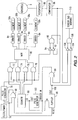
- Figure 2 is a functional illustration of the circuitry wherein the logic gates, electronic components and circuitry can be variously embodied as, for example, in a microprocessor, or a microcontroller.
- a clock/timer 66 generates an electrical signal at a predetermined interval as, for example, once per month. This signal is conducted through OR gate 68 to pulse generator 70. Pulse generator 70 produces an output signal of predetermined voltage and duration in response to the signal from OR gate 68. The output signal is conducted to AND gates 72, 74, 76 and 78.
- Counter 80 provides a binary gate incremental selection signal to AND gates 72, 74, 76, and 78.
- the selecting signal is the binary code designation for the gas generator element that is to be activated.
- the signal from counter 80 is provided coterminally with the signal from pulse generator 70 to AND gates 72, 74, 76 and 78. In this way, counter 80 and AND gates 72, 74, 76 and 78 gate the output of pulse generator 70 and provide a binary input signal from AND gates 72, 74, 76 and 78 to a multiplexer 82.
- Multiplexer 82 is connected to a parallel array of drivers 84a-84n.
- Each of the drivers 84a-84n comprises a power circuit that is connected to a respective carbon monoxide generating element 58a-58n.
- Multiplexer 82 triggers one of drivers 84a-84n in response to the binary input signal from AND gates 72, 74, 76 and 78.
- Driver 84a-84n then energizes the respective carbon monoxide generating element 58a-58n to generate carbon monoxide.
- Sensor 8 is controlled by a potentiostat 86.
- the output of potentiostat 86 is compared to a reference potential in a comparator 88. If comparator 88 determines that the signal from potentiostat 86 indicates that sensor 8 is responsive to the carbon monoxide, a positive test is completed. However, if comparator 88 determines that the signal from potentiostat 86 indicates that sensor 8 is not responsive to the carbon monoxide, the test is initially negative and other failure modes are tested.
- comparator 88 indicates that sensor 8 is non-responsive to the carbon monoxide
- the output of comparator 88 is transmitted to AND gate 90 through an inverter 92.
- the output of pulse generator 70 is also connected to AND gate 90 through an inverter 94 so that AND gate 90 produces a signal when comparator 88 indicates a sensor failure and pulse generator 70 is low.
- the output of AND gate 90 is conducted to AND gate 96 which is also connected to the output of flip-flop 98.
- the initialization signal from clock/timer 66 to OR gate 68 and pulse generator 70 is also conducted to flip-flop 98 to reset the flip-flop and produce a high signal at output 100.
- the high signal from output 100 and the signal from AND gate 90 produce an output from AND gate 96.
- the output from AND gate 96 is conducted to a second pulse generator 102 which provides an incremental signal to counter 80. At the same time, the output of pulse generator 102 changes the state of flip-flip 98 so that output 100 is low.
Landscapes
- Chemical & Material Sciences (AREA)
- Life Sciences & Earth Sciences (AREA)
- Health & Medical Sciences (AREA)
- Physics & Mathematics (AREA)
- General Physics & Mathematics (AREA)
- Immunology (AREA)
- Pathology (AREA)
- Analytical Chemistry (AREA)
- Biochemistry (AREA)
- General Health & Medical Sciences (AREA)
- Engineering & Computer Science (AREA)
- Electrochemistry (AREA)
- Chemical Kinetics & Catalysis (AREA)
- Molecular Biology (AREA)
- Combustion & Propulsion (AREA)
- Food Science & Technology (AREA)
- Medicinal Chemistry (AREA)
- Investigating Or Analyzing Materials By The Use Of Electric Means (AREA)
- Investigating Or Analyzing Materials By The Use Of Fluid Adsorption Or Reactions (AREA)
- Measuring Oxygen Concentration In Cells (AREA)
- Sampling And Sample Adjustment (AREA)
Abstract
Description
Claims (13)
- An element for generating carbon monoxide in response to electrical power, said element comprisinga base (60);at least one resistor (58) that is mechanically connected to said base (60) and that has contacts for connection to the electrical power source; anda coating over said resistor, said coating including an oxalate salt of a metal, a binder, and a thickener.
- The element of claim 1 wherein the metal is selected from the group consisting of alkali metals and alkaline earth metals or wherein the metal of the metal oxalate is selected from the group consisting of sodium, lithium, calcium, potassium and magnesium.
- The element of claim 1 or 2 wherein the binder is a negatively charged hydrophobic colloid or wherein the binder comprises an aqueous suspension of polytetrafloroethelyene resin particles, a non-ionic wetting agent, and a stabilizer or wherein the binder comprises Teflon 30 with 60% by weight of 0.05 to 0.5 um polytetrafloroethelyene resin particles or wherein the binder is an aqueous suspension of polytetrafloroethylene resin particles, a non-ionic wetting agent, and a stabilizer.
- The element according to one of the preceding claims wherein the thickener is a hydroxyethylcellulose.
- The element according to one of the preceding claims in combination with means for generating an electrical voltage signal (70) having substantially predetermined amplitude and duration wherein said element includes:an array of resistors, each of said resistors, (58a - 58n) being selectively connected to said generating means, each of said resistors increasing in temperature in response to the electrical voltage signal of said generating means; anda coating on each of said resistors, said coating being of a compound that emits a predetermined gas in response to increases in the temperature of said resistor.
- The combination of claim 5 wherein said generating means comprises:a pulse generator (70) that produces a voltage pulse at a predetermined frequency and with a predetermined pulse width; anda network (72 - 84) that is connected to said pulse generator and to said array of resistors (58a - 58n), said network selectivity connecting one of the resistors of said array of resistors to said pulse generator.
- The combination of claim 5 wherein said generating means comprises:an electrical voltage source (70), anda network (72 - 84) that is connected to said voltage source and to said array of resistors, said network connecting said resistors individually to said voltage source in predetermined succession.
- The combination of claim 5 wherein said combination provides a positive or negative test result, said generating means comprises:all electrical voltage source (70); anda network (72 - 84) that is connected to said voltage source and to said array of resistors, said network connecting said resistors individually to said voltage source in accordance with a negative test result of said testing apparatus.
- The combination according to one of the claims 5 to 8 wherein said combination provides an output signal in response to exposure to a predetermined gas, said combination further comprising:means for comparing (90) the output signal of the gas sensor to the voltage signal of said generating means; andmeans for switching (96 - 102, 72 - 82, 66, 68) the generating means to another resistor in response to an output signal from said comparing means.
- A gas sensor comprising:the element according to one of the claims 1 to 4;a sensor body (10) having an internal chamber (14);an electrolyte (34) that is maintained in said chamber;a plurality of electrodes (26, 28, 30) that are mounted on a substrate (24), each of said electrodes being disposed in contact with said electrolyte; anda cover (36) that engages said body (10) and that cooperates with said substrate to define a gas diffusion path, (46, 44, 24) between the outside of said cover and said electrodes; wherein said element is located between the cover and the substrate such that carbon monoxide is omitted to the gas diffusion path (46, 44, 24).
- A gas sensor comprising:the element according to one of the claims 1 to 4;a body (10) having a plurality of electrically conductive portions (16, 18, 20) and an electrically non-conductive portion (12) that is spaced between said electrically conductive portions, said electrically conductive portions and said electrically non-conductive portion cooperating to define an internal chamber (14);an electrolyte (34) that is maintained in said chamber;a plurality of electrodes (26, 28, 30) that are mounted in a substrate (24), each of said electrodes being in contact with said electrolyte, each of said electrodes also being electrically connected to a respective one of said electrically conductive portions (16, 18, 20) of said body;means (36) for mechanically urging said electrodes against said electrically conductive portions of said body, said urging means also cooperating with said substrate to define a gas diffusion path such that said element emits carbon monoxide within the gas diffusion path (46, 44, 24).
- The gas sensor of claim 11 wherein said means for mechanically urging said electrodes against said electrically conductive portions of said body comprises a cover (36) that engages said body (10) and a rubber gasket (40) that is disposed between said substrate (24) and said cover (36).
- The element according to one of the claims 1 to 4 wherein said element includes an array of electrical resistors (58a - 58n) that are attached to said base, wherein one end of each resistor is electrically connected to a common electrical terminal and where the other end of each resistor (58a - 58n) is connected to an electrically open circuit; and wherein said element also includes a coating on each of said resistors (58a - 58n), said coating emitting a predetermined gas in response to a temperature increase of said coating.
Applications Claiming Priority (2)
| Application Number | Priority Date | Filing Date | Title |
|---|---|---|---|
| US891235 | 1997-07-10 | ||
| US08/891,235 US6098523A (en) | 1997-07-10 | 1997-07-10 | Testing apparatus for gas sensors |
Publications (2)
| Publication Number | Publication Date |
|---|---|
| EP0890837A2 true EP0890837A2 (en) | 1999-01-13 |
| EP0890837A3 EP0890837A3 (en) | 2002-01-30 |
Family
ID=25397835
Family Applications (1)
| Application Number | Title | Priority Date | Filing Date |
|---|---|---|---|
| EP98112911A Withdrawn EP0890837A3 (en) | 1997-07-10 | 1998-07-10 | Testing apparatus for gas sensors |
Country Status (5)
| Country | Link |
|---|---|
| US (1) | US6098523A (en) |
| EP (1) | EP0890837A3 (en) |
| JP (1) | JPH11101767A (en) |
| AU (1) | AU748825B2 (en) |
| CA (1) | CA2238141A1 (en) |
Cited By (10)
| Publication number | Priority date | Publication date | Assignee | Title |
|---|---|---|---|---|
| EP1281957A1 (en) * | 2001-07-30 | 2003-02-05 | Siemens Building Technologies AG | Combustible gas detector with self-testing device |
| WO2001098767A3 (en) * | 2000-06-20 | 2003-02-13 | Draeger Safety Inc | Testing apparatus for gas sensors |
| WO2003067253A2 (en) | 2002-02-07 | 2003-08-14 | Walter Kidde Portable Equipment, Inc. | Self-calibrating carbon monoxide detector and method |
| US6632674B1 (en) | 1999-03-31 | 2003-10-14 | Industrial Scientific Corporation | Method of testing gas detection instruments and associated apparatus |
| DE102005017445A1 (en) * | 2005-04-15 | 2006-10-26 | Dräger Safety AG & Co. KGaA | Gas measuring system with gas sensor and gas generator |
| WO2006127410A1 (en) * | 2005-05-24 | 2006-11-30 | Honeywell International Inc. | Carbon dioxide sensor comprising co2 calibration gas generator |
| DE102006038364B3 (en) * | 2006-08-16 | 2007-08-30 | Dräger Safety AG & Co. KGaA | Electrochemical gas generator for carbon monoxide |
| EP2273467A3 (en) * | 2000-09-29 | 2012-04-11 | Tormaxx GmbH | Gas generator or heat generator, smoke generator and method for checking a gas detector or a heat detector |
| US8826724B2 (en) | 2010-12-24 | 2014-09-09 | Honeywell International Inc. | Carbon dioxide sensor |
| WO2020068783A1 (en) * | 2018-09-27 | 2020-04-02 | Rosemount Inc | Self-contained sensor module for hazardous locations |
Families Citing this family (15)
| Publication number | Priority date | Publication date | Assignee | Title |
|---|---|---|---|---|
| US6282940B1 (en) * | 1999-06-07 | 2001-09-04 | Patrick Plastics Inc. | Apparatus for testing carbon monoxide alarms |
| GB2373048A (en) * | 2001-03-05 | 2002-09-11 | Central Research Lab Ltd | Testing gas detectors |
| US7619867B2 (en) * | 2002-10-10 | 2009-11-17 | International Business Machines Corporation | Conformal coating enhanced to provide heat detection |
| US20050178186A1 (en) * | 2004-02-13 | 2005-08-18 | Omegapoint Systems, Llc | Gas sensor |
| DE102005003050B3 (en) * | 2005-01-22 | 2006-06-29 | Dräger Safety AG & Co. KGaA | Gas sensor, for use e.g. in chemical or petroleum plants, including porous, gas-permeable, water-impermeable cap for protection against harsh environments, fittable with calibration gas supplying adapter |
| US20080156071A1 (en) * | 2006-12-29 | 2008-07-03 | Peter Tobias | Gas sensor calibration from fluid |
| US7716978B2 (en) * | 2007-10-26 | 2010-05-18 | Baker Hughes Incorporated | High resolution capacitance high conductivity fluid sensor |
| US9952125B2 (en) * | 2013-10-11 | 2018-04-24 | Draeger Medical Systems, Inc. | Remote sampling bypass for a gas analyser |
| DE102014002502B4 (en) * | 2014-02-21 | 2021-08-05 | Dräger Safety AG & Co. KGaA | Electrochemical gas sensor and use of an electrochemical gas sensor |
| US9989492B1 (en) * | 2015-03-18 | 2018-06-05 | Maxim Integrated Products, Inc. | Mobile electrochemical air quality meter |
| US9983164B1 (en) * | 2015-03-18 | 2018-05-29 | Maxim Integrated Products, Inc. | Mobile electrochemical air quality meter |
| CN105806681B (en) * | 2016-06-06 | 2020-06-23 | 北京雪迪龙科技股份有限公司 | Standard gas distribution control method and system and standard gas distribution instrument |
| CN106093301B (en) * | 2016-06-06 | 2020-09-15 | 北京雪迪龙科技股份有限公司 | Standard gas generation control method and system under working condition and standard gas distribution instrument |
| CN112050845B (en) * | 2020-09-11 | 2024-08-06 | 华中科技大学 | Performance testing device of quartz crystal microbalance sensor |
| CN113436518A (en) * | 2021-05-27 | 2021-09-24 | 浙江集赞电子科技有限公司 | Teaching display device based on carbon dioxide sensor |
Family Cites Families (42)
| Publication number | Priority date | Publication date | Assignee | Title |
|---|---|---|---|---|
| US2726205A (en) * | 1952-09-02 | 1955-12-06 | Dearborn Stove Company | Anode deterioration indicator for water heaters |
| US3247702A (en) * | 1964-02-21 | 1966-04-26 | Beckman Instruments Inc | Method of calibrating gas analyzers |
| US3873267A (en) * | 1972-08-07 | 1975-03-25 | Swartz Allen Irving | Oxygen or carbon monoxide detector |
| US4025412A (en) * | 1975-12-04 | 1977-05-24 | General Electric Company | Electrically biased two electrode, electrochemical gas sensor with a H.sub.2 |
| DE2621677A1 (en) * | 1976-05-15 | 1977-11-24 | Bayer Ag | PROCEDURE FOR CHECKING GAS ANALYZERS |
| US4203786A (en) * | 1978-06-08 | 1980-05-20 | Allied Chemical Corporation | Polyethylene binder for pyrotechnic composition |
| US4227984A (en) * | 1979-03-01 | 1980-10-14 | General Electric Company | Potentiostated, three-electrode, solid polymer electrolyte (SPE) gas sensor having highly invariant background current characteristics with temperature during zero-air operation |
| US4268370A (en) * | 1980-01-11 | 1981-05-19 | Beckman Instruments, Inc. | High temperature, CO2 interference free, electrochemical O2 sensor |
| DE3033796A1 (en) * | 1980-09-09 | 1982-04-22 | Bayer Ag, 5090 Leverkusen | ELECTROCHEMICAL SENSOR FOR DETECTING REDUCING GASES, ESPECIALLY CARBON MONOXIDE, HYDRAZINE AND HYDROGEN IN AIR |
| US4384925A (en) * | 1980-10-24 | 1983-05-24 | Becton Dickinson And Company | Gas sensing unit with automatic calibration method |
| EP0095277A3 (en) * | 1982-05-26 | 1984-07-04 | City Technology Limited | Gas sensor |
| JPS59119249A (en) * | 1982-12-25 | 1984-07-10 | Nohmi Bosai Kogyo Co Ltd | Detecting element of carbon monoxide and its production |
| US4525266A (en) * | 1983-10-13 | 1985-06-25 | Allied Corporation | Electrochemical gas sensor |
| US4522690A (en) * | 1983-12-01 | 1985-06-11 | Honeywell Inc. | Electrochemical sensing of carbon monoxide |
| US4568445A (en) * | 1984-12-21 | 1986-02-04 | Honeywell Inc. | Electrode system for an electro-chemical sensor for measuring vapor concentrations |
| US4615340A (en) * | 1985-02-27 | 1986-10-07 | Becton, Dickinson And Company | Sensor assembly suitable for blood gas analysis and the like and the method of use |
| US4695361A (en) * | 1985-11-04 | 1987-09-22 | Seatronics, Inc. | Oxygen sensor |
| JPS62218852A (en) * | 1986-03-20 | 1987-09-26 | Riken Keiki Kk | Electrochemical type gas detector |
| US4769122A (en) * | 1987-07-10 | 1988-09-06 | Bacharach, Inc. | Compact electrochemical cell for gas detection |
| US4874500A (en) * | 1987-07-15 | 1989-10-17 | Sri International | Microelectrochemical sensor and sensor array |
| CH678660A5 (en) * | 1988-02-24 | 1991-10-15 | Matsushita Electric Works Ltd | |
| US4965556A (en) * | 1988-03-08 | 1990-10-23 | Seatt Corporation | Combustion products detector having self-actuated periodic testing signal |
| DE3841621A1 (en) * | 1988-12-10 | 1990-07-12 | Draegerwerk Ag | ELECTROCHEMICAL MEASURING CELL WITH MICROSTRUCTURED CAPILLARY OPENINGS IN THE MEASURING ELECTRODE |
| GB8907564D0 (en) * | 1989-04-04 | 1989-05-17 | Neotronics Technology Plc | Fault detection in electrochemical gas sensing equipment |
| US5228974A (en) * | 1989-04-29 | 1993-07-20 | Dragerwerk Aktiengesellschaft | Electrochemical measuring cell for determining ammonia or hydrazine in a measuring sample |
| DE3921528A1 (en) * | 1989-06-30 | 1991-01-10 | Draegerwerk Ag | MEASURING CELL FOR ELECTROCHEMICAL GAS DETECTION |
| GB2235050B (en) * | 1989-08-14 | 1994-01-05 | Sieger Ltd | Electrochemical gas sensor |
| US5302274A (en) * | 1990-04-16 | 1994-04-12 | Minitech Co. | Electrochemical gas sensor cells using three dimensional sensing electrodes |
| US5173166A (en) * | 1990-04-16 | 1992-12-22 | Minitech Co. | Electrochemical gas sensor cells |
| DE4018597A1 (en) * | 1990-06-09 | 1991-12-12 | Draegerwerk Ag | MEASURING ELECTRODE FOR AN ELECTROCHEMICAL GAS MEASURING CELL |
| JPH0765946B2 (en) * | 1990-09-27 | 1995-07-19 | タツタ電線株式会社 | Leak detection sheet |
| US5492611A (en) * | 1991-03-20 | 1996-02-20 | Fujitsu Limited | Miniaturized oxygen electrode |
| GB2254696A (en) * | 1991-04-09 | 1992-10-14 | Emi Plc Thorn | Gas sensor and calibration device |
| US5250171A (en) * | 1991-05-10 | 1993-10-05 | University Of Kansas | Sensor for carbon monoxide |
| DE4232295C2 (en) * | 1992-09-26 | 1996-03-14 | Draegerwerk Ag | Electrochemical gas sensor with disc-shaped electrodes, which are also electrical contact leads |
| GB9422334D0 (en) * | 1994-11-04 | 1994-12-21 | Central Research Lab Ltd | Gas sensor |
| US5744657A (en) * | 1994-12-22 | 1998-04-28 | E. I. Du Pont De Nemours And Company | Process for the preparation of perfluorocarbons |
| US5573648A (en) * | 1995-01-31 | 1996-11-12 | Atwood Systems And Controls | Gas sensor based on protonic conductive membranes |
| GB9510454D0 (en) * | 1995-05-24 | 1995-07-19 | City Tech | Electrochemical gas sensor assembly |
| US5554272A (en) * | 1995-08-10 | 1996-09-10 | Ciba Corning Diagnostics Corp. | Planar bicarbonate sensor |
| US5744697A (en) * | 1995-08-16 | 1998-04-28 | J And N Associates, Inc. | Gas sensor with conductive housing portions |
| KR0176212B1 (en) * | 1995-10-26 | 1999-05-15 | 이형도 | A / F sensor self-diagnosis method and apparatus |
-
1997
- 1997-07-10 US US08/891,235 patent/US6098523A/en not_active Expired - Fee Related
-
1998
- 1998-06-22 AU AU73096/98A patent/AU748825B2/en not_active Ceased
- 1998-06-23 CA CA002238141A patent/CA2238141A1/en not_active Abandoned
- 1998-07-10 JP JP10195996A patent/JPH11101767A/en active Pending
- 1998-07-10 EP EP98112911A patent/EP0890837A3/en not_active Withdrawn
Cited By (17)
| Publication number | Priority date | Publication date | Assignee | Title |
|---|---|---|---|---|
| US6632674B1 (en) | 1999-03-31 | 2003-10-14 | Industrial Scientific Corporation | Method of testing gas detection instruments and associated apparatus |
| WO2001098767A3 (en) * | 2000-06-20 | 2003-02-13 | Draeger Safety Inc | Testing apparatus for gas sensors |
| EP2273467A3 (en) * | 2000-09-29 | 2012-04-11 | Tormaxx GmbH | Gas generator or heat generator, smoke generator and method for checking a gas detector or a heat detector |
| EP1281957A1 (en) * | 2001-07-30 | 2003-02-05 | Siemens Building Technologies AG | Combustible gas detector with self-testing device |
| WO2003067253A2 (en) | 2002-02-07 | 2003-08-14 | Walter Kidde Portable Equipment, Inc. | Self-calibrating carbon monoxide detector and method |
| WO2003067253A3 (en) * | 2002-02-07 | 2003-11-20 | Kidde Portable Equipment Inc | Self-calibrating carbon monoxide detector and method |
| US6948352B2 (en) | 2002-02-07 | 2005-09-27 | Walter Kidde Portable Equipment, Inc. | Self-calibrating carbon monoxide detector and method |
| CN100430722C (en) * | 2002-02-07 | 2008-11-05 | 沃特基德手提设备股份有限公司 | Self-checking carbon monoxide detector and method |
| US7645367B2 (en) | 2005-04-15 | 2010-01-12 | Dräger Safety AG & Co. KGaA | Gas-measuring system with gas sensor and gas generator |
| DE102005017445A1 (en) * | 2005-04-15 | 2006-10-26 | Dräger Safety AG & Co. KGaA | Gas measuring system with gas sensor and gas generator |
| DE102005017445B4 (en) * | 2005-04-15 | 2011-11-17 | Dräger Safety AG & Co. KGaA | Gas measuring system with gas sensor and gas generator |
| US7174766B2 (en) | 2005-05-24 | 2007-02-13 | Honeywell International Inc. | Calibration device for carbon dioxide sensor |
| WO2006127410A1 (en) * | 2005-05-24 | 2006-11-30 | Honeywell International Inc. | Carbon dioxide sensor comprising co2 calibration gas generator |
| US7951273B2 (en) | 2006-08-16 | 2011-05-31 | Draeger Safety Ag & Co. Kgaa | Electrochemical gas generator for carbon monoxide |
| DE102006038364B3 (en) * | 2006-08-16 | 2007-08-30 | Dräger Safety AG & Co. KGaA | Electrochemical gas generator for carbon monoxide |
| US8826724B2 (en) | 2010-12-24 | 2014-09-09 | Honeywell International Inc. | Carbon dioxide sensor |
| WO2020068783A1 (en) * | 2018-09-27 | 2020-04-02 | Rosemount Inc | Self-contained sensor module for hazardous locations |
Also Published As
| Publication number | Publication date |
|---|---|
| AU7309698A (en) | 1999-01-21 |
| US6098523A (en) | 2000-08-08 |
| CA2238141A1 (en) | 1999-01-10 |
| JPH11101767A (en) | 1999-04-13 |
| EP0890837A3 (en) | 2002-01-30 |
| AU748825B2 (en) | 2002-06-13 |
Similar Documents
| Publication | Publication Date | Title |
|---|---|---|
| US6098523A (en) | Testing apparatus for gas sensors | |
| US6358384B1 (en) | Electrochemical sensor for detecting a predetermined gas | |
| US8317998B2 (en) | Methods of operation of electrochemical gas sensors | |
| US6200443B1 (en) | Gas sensor with a diagnostic device | |
| US6428684B1 (en) | Method and apparatus for diagnosing the condition of a gas sensor | |
| US6096186A (en) | Method for determining exhaustion of an electrochemical gas sensor | |
| GB2155185A (en) | Gas detector incorporating sensor array | |
| US3718568A (en) | Electrochemical sensor instrumentation | |
| CA1229383A (en) | Electrochemical cell and method for the detection of noxious gases | |
| US5733436A (en) | Method for determining the state of an electrochemical gas sensor | |
| CA2051099A1 (en) | Fault detection in electrochemical gas sensing equipment | |
| US20010045119A1 (en) | Method and apparatus for determining concentration of a gas | |
| US11085896B2 (en) | Auxiliary micro-electrodes for diagnostics of electrochemical gas sensors | |
| KR100833835B1 (en) | Hydrogen gas sensor | |
| US20110108418A1 (en) | Gas sensor with test gas generator | |
| US4859305A (en) | Electrochemical cell | |
| US7645367B2 (en) | Gas-measuring system with gas sensor and gas generator | |
| US4797180A (en) | Method for the detection of noxious gases | |
| US4333810A (en) | Analyzer for chemical oxidizing or reducing agents | |
| GB2253910A (en) | Detecting a gaseous, vaporous or colloidal component of a gaseous medium. | |
| JP2018529936A (en) | Refrigerant analyzer and method of using refrigerant analyzer | |
| CN115436443B (en) | Gas exposure dose detection device and method | |
| JP3925191B2 (en) | Constant-potential electrolysis gas sensor | |
| GB2074323A (en) | Apparatus for Detecting Hydrogen Cyanide Gas | |
| CA1150770A (en) | Method and device for the detection of hydrazine |
Legal Events
| Date | Code | Title | Description |
|---|---|---|---|
| PUAI | Public reference made under article 153(3) epc to a published international application that has entered the european phase |
Free format text: ORIGINAL CODE: 0009012 |
|
| AK | Designated contracting states |
Kind code of ref document: A2 Designated state(s): AT BE CH CY DE DK ES FI FR GB GR IE IT LI LU MC NL PT SE |
|
| AX | Request for extension of the european patent |
Free format text: AL;LT;LV;MK;RO;SI |
|
| PUAL | Search report despatched |
Free format text: ORIGINAL CODE: 0009013 |
|
| AK | Designated contracting states |
Kind code of ref document: A3 Designated state(s): AT BE CH CY DE DK ES FI FR GB GR IE IT LI LU MC NL PT SE |
|
| AX | Request for extension of the european patent |
Free format text: AL;LT;LV;MK;RO;SI |
|
| GRAH | Despatch of communication of intention to grant a patent |
Free format text: ORIGINAL CODE: EPIDOS IGRA |
|
| 17P | Request for examination filed |
Effective date: 20020704 |
|
| AKX | Designation fees paid |
Free format text: AT BE CH DE DK ES FI FR GB IE IT LI LU NL PT SE |
|
| GRAH | Despatch of communication of intention to grant a patent |
Free format text: ORIGINAL CODE: EPIDOS IGRA |
|
| STAA | Information on the status of an ep patent application or granted ep patent |
Free format text: STATUS: THE APPLICATION IS DEEMED TO BE WITHDRAWN |
|
| 18D | Application deemed to be withdrawn |
Effective date: 20030729 |