EP0890847B1 - Vorrichtung zur Ermittlung der magnetischen Feldstärke des Erdmagnetfeldes, insbesondere in einer Fahrzeugnavigationseinrichtung - Google Patents
Vorrichtung zur Ermittlung der magnetischen Feldstärke des Erdmagnetfeldes, insbesondere in einer Fahrzeugnavigationseinrichtung Download PDFInfo
- Publication number
- EP0890847B1 EP0890847B1 EP98112436A EP98112436A EP0890847B1 EP 0890847 B1 EP0890847 B1 EP 0890847B1 EP 98112436 A EP98112436 A EP 98112436A EP 98112436 A EP98112436 A EP 98112436A EP 0890847 B1 EP0890847 B1 EP 0890847B1
- Authority
- EP
- European Patent Office
- Prior art keywords
- magnetic field
- control unit
- operating circuit
- measured values
- measured
- Prior art date
- Legal status (The legal status is an assumption and is not a legal conclusion. Google has not performed a legal analysis and makes no representation as to the accuracy of the status listed.)
- Expired - Lifetime
Links
- 238000005259 measurement Methods 0.000 claims abstract description 21
- 238000000034 method Methods 0.000 claims abstract description 12
- 238000011156 evaluation Methods 0.000 claims abstract description 9
- 230000008569 process Effects 0.000 claims abstract description 4
- 230000001105 regulatory effect Effects 0.000 abstract 4
- 230000008859 change Effects 0.000 description 3
- 238000012935 Averaging Methods 0.000 description 2
- 238000013459 approach Methods 0.000 description 2
- 238000001514 detection method Methods 0.000 description 2
- 230000003071 parasitic effect Effects 0.000 description 2
- 230000009471 action Effects 0.000 description 1
- 230000006978 adaptation Effects 0.000 description 1
- 230000006399 behavior Effects 0.000 description 1
- 230000009286 beneficial effect Effects 0.000 description 1
- 230000008901 benefit Effects 0.000 description 1
- 238000013500 data storage Methods 0.000 description 1
- 230000001419 dependent effect Effects 0.000 description 1
- 238000013461 design Methods 0.000 description 1
- 238000010586 diagram Methods 0.000 description 1
- 230000008030 elimination Effects 0.000 description 1
- 238000003379 elimination reaction Methods 0.000 description 1
- 230000004907 flux Effects 0.000 description 1
- 230000005415 magnetization Effects 0.000 description 1
- 238000012545 processing Methods 0.000 description 1
- 230000001953 sensory effect Effects 0.000 description 1
- 230000001629 suppression Effects 0.000 description 1
Images


Classifications
-
- G—PHYSICS
- G01—MEASURING; TESTING
- G01R—MEASURING ELECTRIC VARIABLES; MEASURING MAGNETIC VARIABLES
- G01R33/00—Arrangements or instruments for measuring magnetic variables
- G01R33/02—Measuring direction or magnitude of magnetic fields or magnetic flux
- G01R33/0206—Three-component magnetometers
-
- G—PHYSICS
- G01—MEASURING; TESTING
- G01C—MEASURING DISTANCES, LEVELS OR BEARINGS; SURVEYING; NAVIGATION; GYROSCOPIC INSTRUMENTS; PHOTOGRAMMETRY OR VIDEOGRAMMETRY
- G01C17/00—Compasses; Devices for ascertaining true or magnetic north for navigation or surveying purposes
- G01C17/02—Magnetic compasses
- G01C17/28—Electromagnetic compasses
Definitions
- the invention relates to a device for determining the magnetic field strength of the earth's magnetic field according to the preamble of the first claim.
- the components of the earth's magnetic field are used in many automotive Applications - such as navigation devices, electronic Compasses or accident data storage - through orthogonal Magnetic field sensors arranged relative to one another, which for example are realized by coils.
- orthogonal Magnetic field sensors arranged relative to one another, which for example are realized by coils.
- the magnetic field sensors integrated in circuit arrangements that the signals the magnetic field sensors to a transportable and evaluable Prepare the measured value.
- This circuitry form the operating circuit of the magnetic field sensors.
- a generic device is such. B from document US 5,644,851. Accordingly, the direction of the earth's magnetic field to determine two orthogonally aligned Magnetic field sensors alternately read out and out the obtained direction and magnitude of the earth's magnetic field certainly. Magneto-resistive elements are used.
- the operating circuit described supplies its measurement signal further evaluation to a control unit.
- To the accuracy increasing the measurement will be a certain number of consecutive Measured values in one assigned to the control unit Cached memory.
- calculate the Control unit the average over this number of measured values and stores this mean value for further signal evaluation.
- This procedure is in scripture, for example EP 0 596 320 A1.
- Averaging takes place in all spatial directions simultaneously and in parallel for the measurement signals from all operational circuits.
- considerable storage and computing resources are available ask, which is also disadvantageous for cost reasons.
- Moreover such an approach creates a fairly complex, and thus memory-intensive structure for the control program.
- the object of the present invention to provide a device point out, which is suitable, the components of the Earth's magnetic field exactly and time-correlated, with special consideration the conditions prevailing in a vehicle. It is intended to use the operating circuit described can be assumed for a magnetic field sensor. However, the operating circuit should be avoided several times provided. So the goal is to build and programming expenditure for a generic device, and with it the costs for their realization reduce, without sacrificing the quality of the measured values.
- a device according to claim 1 is proposed.
- the advantage of the proposed method is that the measuring arrangement requires only a single operating circuit, and yet record measured values of a spatial magnetic field can. Furthermore, no individual values are collected, but depending on the direction of space, the Average values correlating with each other with sufficient accuracy formed from short sequences of measured values, their accuracy of information is higher than that of single measurements.
- Figure 1 shows a simplified block diagram of the measurement setup to carry out the proposed Process.
- Figure 2 shows the operating circuit according to DE 195 38 757 C1, which further developed the present solution.
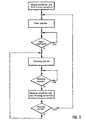
- Figure 3 shows a flow chart for the sensor control.
- an LC oscillator 1 is operated with a first coil 2.
- the field strength-dependent, sinusoidal oscillator frequency f osz is converted into a square-wave signal by a suitable adaptation circuit 4 and then one to frequency-voltage converter 5 supplied, whose output is connected to a subtractor 6, to which a of the instantaneous oscillator frequency osz proportional voltage value f u u is from a fixed voltage reference value corresponding to the ideal nominal frequency f to the oscillator corresponds, is subtracted.
- the reference frequency f ref of the oscillator is the frequency which the oscillator 1 in the unloaded state, ie in the absence of said target field HE, assumes in its operating point, wherein the U denotes the component to be measured in the magnetic field coil longitudinal direction.
- the difference between the two voltage values usoll and uist is fed to a controller 7, which adjusts the operating current 1 for the compensation coil 3 in such a way that the voltage difference (u soll - u ist ) approaches zero and the change in the inductance 2 caused by the measuring field HE and the resulting change in the oscillator frequency f Osz is compensated, whereby the oscillator frequency f osz remains more or less constant depending on the control speed of the control loop.
- the amplitude of the operating current 1 for the compensation coil 3 is the strength of the component of the measuring field HE in the longitudinal direction of the coil directly proportional and changes with it equally as the strength of the measuring field.
- the real one Measured variable is therefore by evaluating the amplitude of the operating current 1 can be derived directly. For this, the through the Compensation coil 3 flowing operating current I over a Shunt resistor 10 to ground GND conducted to the current I make it evaluable as a voltage signal. However, since only the DC component of this voltage signal is a measured variable is a proportional measure, the voltage signal is via a as Low-pass filter element 11 an analog-digital converter 12 fed for further processing, which in a subordinate control unit, not shown in this figure he follows.
- FIG. 1 shows in simplified form the proposed measurement setup, where a magnetic field sensor Mx, My and Mz is provided. Every magnetic field sensor should be off consist of a coil arrangement, as shown in Figure 2 is.
- the ferromagnetically biased measuring coil 2 can do this be wound with the compensation coil 3, both However, coils remain electrically isolated from each other. It is advantageous to wind the coils in opposite directions.
- the circuit structure of Figure 2 corresponds to the changeover switch pairs 9a, 9b and 14a, 14b formed so that the magnetic field sensors by the actuations 8 and 13 Mx, My and Mz cyclically with the control electronics the operating circuit BS are connected.
- the operations 8 and 13 are in a fixed cycle from one Control unit ⁇ C by a microcontroller or another logic unit is realized, controlled. You can program-controlled switching states on output circuits of the microcontroller, which makes the changeover switch pairs 9a, 9b and 14a, 14b brought into a defined position become.
- the proposed procedure now brings the first magnetic field sensor Mx in operative connection with the operating circuit. Then a number of n Measured values recorded and via the A / D converter 12 to the Control unit ⁇ C delivered, which calculates the mean value and this in a memory Sp stores. The control unit ⁇ C then switches the direction of energization in the measuring coil 2 and the compensation coil 3 around and again takes a certain number of m measured values with which the procedure is as described above. This procedure is carried out with the magnetic field sensors My and if necessary repeat Mz before measuring values from the first Magnetic field sensor Mx are included.
- the measuring coil 2 of each magnetic field sensor involved in one Oscillator 1 is operated when determining the Measuring cycle to avoid Measurement errors to ensure that the oscillator is in the steady state Condition. It is advantageous for dimensioning the waiting time between the operation of the toggle switches and the measured value acquisition one of the control unit ⁇ C to use assigned or even integrated timers, because its operation is relatively easy can be integrated into the control program.
- Figure 3 is based on an advantageous embodiment of the measuring routine on.
- the control unit ⁇ C first selects a magnetic field sensor and determines the measuring direction for this. After that a timer is started. After its expiration the actual measurement by being recorded with the magnetic field sensor Measured values are forwarded to the control unit ⁇ C.
- the Measured value evaluation in the control unit ⁇ C begins after completion the sensory data acquisition and exists initially in a determination of the mean value from the just recorded Measured values and from a storage of the calculated mean.
- the control unit selects ⁇ C for another Measured value acquisition the magnetic field sensor and the measuring direction and gives a control signal to the actuations 8 and 13 for the Switching means 9a, 9b and 14a, 14b.
- the measuring arrangement is still in the steady state Condition. Therefore, immediately after the query whether the measuring to start, follow the command to execute it. If the control unit ⁇ C, however, one of the parameters Magnetic field sensor or measuring direction changes, the measuring arrangement be prepared for the measurement first, which is why heard the timer start. In the way described here all existing magnetic field sensors are successively processed. Then the measuring cycle starts again.
Landscapes
- Physics & Mathematics (AREA)
- General Physics & Mathematics (AREA)
- Engineering & Computer Science (AREA)
- Radar, Positioning & Navigation (AREA)
- Remote Sensing (AREA)
- Condensed Matter Physics & Semiconductors (AREA)
- Electromagnetism (AREA)
- Measuring Magnetic Variables (AREA)
- Navigation (AREA)
Description
Claims (2)
- Vorrichtung zur Ermittlung der Komponenten der magnetischen Feldstärke des Erdmagnetfeldes in einer Fahrzeugnavigationseinrichtung, mit wenigstens zwei orthogonal zueinander angeordneten Magnetfeldsensoren, die zur Ermittlung der jeweiligen Feldstärke mit einer einzigen Betriebsschaltung koppelbar sind,
wobei Schalter vorgesehen sind, die zur Erfassung der einzelnen Komponenten der jeweiligen Feldstärke die einzelnen Magnetfeldsensoren für eine bestimmte Messtaktzeit zyklisch nacheinander mit der Betriebsschaltung verbinden, wobei nach einem Zyklus die Betriebsschaltung erneut mit dem ersten Magnetfeldsensor verbunden wird und wobei die jeweils gewonnenen Messwerte von einer Steuereinheit in einem Speicher für eine nachfolgende an eine Regel einrichtung angeschlossen Messwertauswertung gespeichert werden,
dadurch gekennzeichnet, dass
die Vorrichtung so eingerichtet ist, dass zur Bestimmung der einzelnen Komponenten der magnetischen Feldstärke des zu messenden Feldes ein Kompensationsverfahren zum Einsatz kommt, das von der. Regeleinrichtung betrieben wird, bei der das zu messende Erdmagnetfeld durch das Magnetfeld einer Messspule kompensiert wird, und
dass die an die Betriebsschaltung angeschlossene Steuereinheit so einserichtet it, dass sie innerhalb jeder Messtaktzeit eine Folge von mehreren (n) Messwerten von dem aktuell mit der Betriebsschaltung verbundenen Magnetfeldsensor aufnimmt
und dass die Steuereinheit für eine nachfolgende Messwertauswertung den Mittelwert der innerhalb der Messtaktzeit aufgenommenen Messwerte bildet und in einem an der Steuereinheit angeschlossenen elektronischen Speicher speichert. - Vorrichtung nach Anspruch 1, dadurch gekennzeichnet, dass die Steuereinheit die zyklische Ansteuerung der Magnetfeldsensoren sowie den mit ihnen durchgeführten Messvorgang unabhängig von anderen Programmteilen vornimmt.
Applications Claiming Priority (2)
| Application Number | Priority Date | Filing Date | Title |
|---|---|---|---|
| DE19729896 | 1997-07-12 | ||
| DE19729896A DE19729896A1 (de) | 1997-07-12 | 1997-07-12 | Vorrichtung zur Ermittlung der magnetischen Feldstärke des Erdmagnetfeldes, insbesondere in einer Fahrzeugnavigationseinrichtung |
Publications (3)
| Publication Number | Publication Date |
|---|---|
| EP0890847A2 EP0890847A2 (de) | 1999-01-13 |
| EP0890847A3 EP0890847A3 (de) | 2001-08-22 |
| EP0890847B1 true EP0890847B1 (de) | 2004-09-22 |
Family
ID=7835491
Family Applications (1)
| Application Number | Title | Priority Date | Filing Date |
|---|---|---|---|
| EP98112436A Expired - Lifetime EP0890847B1 (de) | 1997-07-12 | 1998-07-04 | Vorrichtung zur Ermittlung der magnetischen Feldstärke des Erdmagnetfeldes, insbesondere in einer Fahrzeugnavigationseinrichtung |
Country Status (4)
| Country | Link |
|---|---|
| EP (1) | EP0890847B1 (de) |
| AT (1) | ATE277358T1 (de) |
| DE (2) | DE19729896A1 (de) |
| ES (1) | ES2229419T3 (de) |
Families Citing this family (1)
| Publication number | Priority date | Publication date | Assignee | Title |
|---|---|---|---|---|
| DE10113131B4 (de) * | 2001-03-17 | 2006-11-16 | Sensitec Gmbh | Anordnung zur Messung der magnetischen Feldstärke oder von örtlichen Differenzen magnetischer Feldstärken, sowie Schaltungsanordnung für die Auswerteeinheit und Verwendungen der Anordnung und der Schaltungsanordnung |
Family Cites Families (3)
| Publication number | Priority date | Publication date | Assignee | Title |
|---|---|---|---|---|
| JPH0493781A (ja) * | 1990-08-10 | 1992-03-26 | Seiko Instr Inc | 三次元積分磁束計 |
| US5644851A (en) * | 1991-12-20 | 1997-07-08 | Blank; Rodney K. | Compensation system for electronic compass |
| DE4237365A1 (de) * | 1992-11-05 | 1994-05-11 | Mannesmann Kienzle Gmbh | Verfahren und Anordnung zur Speicherung von Meßdaten in einem Registriergerät |
-
1997
- 1997-07-12 DE DE19729896A patent/DE19729896A1/de not_active Withdrawn
-
1998
- 1998-07-04 ES ES98112436T patent/ES2229419T3/es not_active Expired - Lifetime
- 1998-07-04 AT AT98112436T patent/ATE277358T1/de not_active IP Right Cessation
- 1998-07-04 DE DE59811981T patent/DE59811981D1/de not_active Expired - Fee Related
- 1998-07-04 EP EP98112436A patent/EP0890847B1/de not_active Expired - Lifetime
Also Published As
| Publication number | Publication date |
|---|---|
| ES2229419T3 (es) | 2005-04-16 |
| DE59811981D1 (de) | 2004-10-28 |
| EP0890847A2 (de) | 1999-01-13 |
| ATE277358T1 (de) | 2004-10-15 |
| DE19729896A1 (de) | 1999-01-14 |
| EP0890847A3 (de) | 2001-08-22 |
Similar Documents
| Publication | Publication Date | Title |
|---|---|---|
| EP0213283B1 (de) | Einrichtung zur Münzenprüfung | |
| DE3741734C2 (de) | Vorrichtung zur Messung der Induktivität einer Spule, insbesondere zur Messung der Ankerstellung eines Spulen/Anker-Magnetsystems | |
| EP0721907B1 (de) | Ultraschall-Kantenfühler zur Erfassung der Bahnkante einer Warenbahn | |
| DE102008015837A1 (de) | Positionsmessgerät und Verfahren zu dessen Betrieb | |
| DE4213926A1 (de) | Elektronische kraftfahrzeugstossstange | |
| EP0849653B1 (de) | Verfahren zur Steuerung eines Koordinatenmessgerätes und Koordinatenmessgerät | |
| DE4103933C2 (de) | Verfahren zum Feststellen der Position eines beweglichen Bauteils und Schaltung für einen Positionssensor | |
| DE3687455T2 (de) | Sensor-verstaerkungs- und steigerungsapparat unter verwendung digitaler techniken. | |
| EP2265964B1 (de) | Verfahren und vorrichtung zur strommessung in phasenleitungen | |
| EP0693674B1 (de) | Vorrichtung mit einem Messtransformator zur Erfassung der position eines linear beweglichen Objektes | |
| DE69132528T2 (de) | Koordinateneingabegerät basierend auf dem Mateucci-Effekt | |
| DE10004080C1 (de) | Sensorvorrichtung und Verfahren zur Erzeugung eines Ausgangssignals einer Sensorvorrichtung | |
| DE69607158T2 (de) | Abfragegerät für ein identifizierungssystem | |
| EP0898368B1 (de) | Sensoreinrichtung | |
| DE2906264C3 (de) | Supraleitender Quanten-Interferenz-Flußmesser | |
| DE4011411C2 (de) | Inkrementales Positionsmeßsystem | |
| DE102017128472B4 (de) | Induktiver Näherungsschalter und Verfahren zum Betreiben eines induktiven Näherungsschalters | |
| DE2520031B2 (de) | Vorrichtung zum bestimmen magnetischer zylinderdomaenen | |
| DE19729896A1 (de) | Vorrichtung zur Ermittlung der magnetischen Feldstärke des Erdmagnetfeldes, insbesondere in einer Fahrzeugnavigationseinrichtung | |
| DE10131760B4 (de) | Verfahren zum Testen eines Sensors | |
| DE3811735C2 (de) | Verfahren zur Frequenzmessung | |
| DE4201721C2 (de) | Berührungsloser Geber | |
| EP0046317B1 (de) | Verfahren und Einrichtung zur Kurzschluss-Richtungsdetektion | |
| DE19826673C2 (de) | Prüfgerät und Prüfverfahren für Elektrizitätszähler | |
| EP0553451A2 (de) | Verfahren und Vorrichtung zur Überwachung der Funktionsweise von Induktivitäten |
Legal Events
| Date | Code | Title | Description |
|---|---|---|---|
| PUAI | Public reference made under article 153(3) epc to a published international application that has entered the european phase |
Free format text: ORIGINAL CODE: 0009012 |
|
| AK | Designated contracting states |
Kind code of ref document: A2 Designated state(s): AT BE CH CY DE DK ES FI FR GB GR IE IT LI LU MC NL PT SE |
|
| AX | Request for extension of the european patent |
Free format text: AL;LT;LV;MK;RO;SI |
|
| PUAL | Search report despatched |
Free format text: ORIGINAL CODE: 0009013 |
|
| AK | Designated contracting states |
Kind code of ref document: A3 Designated state(s): AT BE CH CY DE DK ES FI FR GB GR IE IT LI LU MC NL PT SE |
|
| AX | Request for extension of the european patent |
Free format text: AL;LT;LV;MK;RO;SI |
|
| 17P | Request for examination filed |
Effective date: 20011013 |
|
| AKX | Designation fees paid |
Free format text: AT BE CH DE ES FR GB LI NL SE |
|
| RAP1 | Party data changed (applicant data changed or rights of an application transferred) |
Owner name: SIEMENS AKTIENGESELLSCHAFT |
|
| 17Q | First examination report despatched |
Effective date: 20020725 |
|
| GRAP | Despatch of communication of intention to grant a patent |
Free format text: ORIGINAL CODE: EPIDOSNIGR1 |
|
| GRAS | Grant fee paid |
Free format text: ORIGINAL CODE: EPIDOSNIGR3 |
|
| GRAA | (expected) grant |
Free format text: ORIGINAL CODE: 0009210 |
|
| AK | Designated contracting states |
Kind code of ref document: B1 Designated state(s): AT BE CH DE ES FR GB LI NL SE |
|
| REG | Reference to a national code |
Ref country code: GB Ref legal event code: FG4D Free format text: NOT ENGLISH |
|
| REG | Reference to a national code |
Ref country code: CH Ref legal event code: EP |
|
| REF | Corresponds to: |
Ref document number: 59811981 Country of ref document: DE Date of ref document: 20041028 Kind code of ref document: P |
|
| REG | Reference to a national code |
Ref country code: CH Ref legal event code: NV Representative=s name: SIEMENS SCHWEIZ AG |
|
| REG | Reference to a national code |
Ref country code: SE Ref legal event code: TRGR |
|
| GBT | Gb: translation of ep patent filed (gb section 77(6)(a)/1977) |
Effective date: 20050126 |
|
| REG | Reference to a national code |
Ref country code: ES Ref legal event code: FG2A Ref document number: 2229419 Country of ref document: ES Kind code of ref document: T3 |
|
| PLBE | No opposition filed within time limit |
Free format text: ORIGINAL CODE: 0009261 |
|
| STAA | Information on the status of an ep patent application or granted ep patent |
Free format text: STATUS: NO OPPOSITION FILED WITHIN TIME LIMIT |
|
| ET | Fr: translation filed | ||
| 26N | No opposition filed |
Effective date: 20050623 |
|
| PGFP | Annual fee paid to national office [announced via postgrant information from national office to epo] |
Ref country code: ES Payment date: 20080729 Year of fee payment: 11 Ref country code: DE Payment date: 20080722 Year of fee payment: 11 Ref country code: CH Payment date: 20080715 Year of fee payment: 11 |
|
| PGFP | Annual fee paid to national office [announced via postgrant information from national office to epo] |
Ref country code: NL Payment date: 20080716 Year of fee payment: 11 Ref country code: FR Payment date: 20080715 Year of fee payment: 11 Ref country code: AT Payment date: 20080715 Year of fee payment: 11 |
|
| PGFP | Annual fee paid to national office [announced via postgrant information from national office to epo] |
Ref country code: GB Payment date: 20080722 Year of fee payment: 11 |
|
| PGFP | Annual fee paid to national office [announced via postgrant information from national office to epo] |
Ref country code: SE Payment date: 20080714 Year of fee payment: 11 Ref country code: BE Payment date: 20080814 Year of fee payment: 11 |
|
| REG | Reference to a national code |
Ref country code: CH Ref legal event code: PCAR Free format text: SIEMENS SCHWEIZ AG;INTELLECTUAL PROPERTY FREILAGERSTRASSE 40;8047 ZUERICH (CH) |
|
| BERE | Be: lapsed |
Owner name: *SIEMENS A.G. Effective date: 20090731 |
|
| REG | Reference to a national code |
Ref country code: CH Ref legal event code: PL |
|
| EUG | Se: european patent has lapsed | ||
| GBPC | Gb: european patent ceased through non-payment of renewal fee |
Effective date: 20090704 |
|
| NLV4 | Nl: lapsed or anulled due to non-payment of the annual fee |
Effective date: 20100201 |
|
| REG | Reference to a national code |
Ref country code: FR Ref legal event code: ST Effective date: 20100331 |
|
| PG25 | Lapsed in a contracting state [announced via postgrant information from national office to epo] |
Ref country code: LI Free format text: LAPSE BECAUSE OF NON-PAYMENT OF DUE FEES Effective date: 20090731 Ref country code: FR Free format text: LAPSE BECAUSE OF NON-PAYMENT OF DUE FEES Effective date: 20090731 Ref country code: CH Free format text: LAPSE BECAUSE OF NON-PAYMENT OF DUE FEES Effective date: 20090731 |
|
| PG25 | Lapsed in a contracting state [announced via postgrant information from national office to epo] |
Ref country code: GB Free format text: LAPSE BECAUSE OF NON-PAYMENT OF DUE FEES Effective date: 20090704 |
|
| PG25 | Lapsed in a contracting state [announced via postgrant information from national office to epo] |
Ref country code: DE Free format text: LAPSE BECAUSE OF NON-PAYMENT OF DUE FEES Effective date: 20100202 Ref country code: BE Free format text: LAPSE BECAUSE OF NON-PAYMENT OF DUE FEES Effective date: 20090731 Ref country code: AT Free format text: LAPSE BECAUSE OF NON-PAYMENT OF DUE FEES Effective date: 20090704 |
|
| REG | Reference to a national code |
Ref country code: ES Ref legal event code: FD2A Effective date: 20090706 |
|
| PG25 | Lapsed in a contracting state [announced via postgrant information from national office to epo] |
Ref country code: ES Free format text: LAPSE BECAUSE OF NON-PAYMENT OF DUE FEES Effective date: 20090706 |
|
| PG25 | Lapsed in a contracting state [announced via postgrant information from national office to epo] |
Ref country code: SE Free format text: LAPSE BECAUSE OF NON-PAYMENT OF DUE FEES Effective date: 20090705 |
|
| PG25 | Lapsed in a contracting state [announced via postgrant information from national office to epo] |
Ref country code: NL Free format text: LAPSE BECAUSE OF NON-PAYMENT OF DUE FEES Effective date: 20100201 |