EP0890848B1 - Sonde pour un spectromètre de résonance magnétique nucléaire comprenant une bobine unique réglée sur plusieurs fréquences à l'aide d'un réseau de lignes de transmission - Google Patents
Sonde pour un spectromètre de résonance magnétique nucléaire comprenant une bobine unique réglée sur plusieurs fréquences à l'aide d'un réseau de lignes de transmission Download PDFInfo
- Publication number
- EP0890848B1 EP0890848B1 EP98630034A EP98630034A EP0890848B1 EP 0890848 B1 EP0890848 B1 EP 0890848B1 EP 98630034 A EP98630034 A EP 98630034A EP 98630034 A EP98630034 A EP 98630034A EP 0890848 B1 EP0890848 B1 EP 0890848B1
- Authority
- EP
- European Patent Office
- Prior art keywords
- transmission line
- probe
- radio frequency
- junction point
- impedance
- Prior art date
- Legal status (The legal status is an assumption and is not a legal conclusion. Google has not performed a legal analysis and makes no representation as to the accuracy of the status listed.)
- Expired - Lifetime
Links
Images

Classifications
-
- G—PHYSICS
- G01—MEASURING; TESTING
- G01R—MEASURING ELECTRIC VARIABLES; MEASURING MAGNETIC VARIABLES
- G01R33/00—Arrangements or instruments for measuring magnetic variables
- G01R33/20—Arrangements or instruments for measuring magnetic variables involving magnetic resonance
- G01R33/28—Details of apparatus provided for in groups G01R33/44 - G01R33/64
- G01R33/32—Excitation or detection systems, e.g. using radio frequency signals
- G01R33/36—Electrical details, e.g. matching or coupling of the coil to the receiver
- G01R33/3628—Tuning/matching of the transmit/receive coil
- G01R33/3635—Multi-frequency operation
Definitions
- the present invention relates to probes for nuclear magnetic resonance (NMR) spectrometers and specifically to a capacitance tuned probe employing a single sample coil suitable for multiple radio frequency resonance experiments, wherein the tuning elements of the probe are remotely disposed from the magnetic field, connected to the sample coil by means of coaxial transmission lines.
- NMR nuclear magnetic resonance
- a high-intensity uniform magnetic field is generated within an extremely strong magnet. Inserted into the axial bore of the magnet is the sample to be analyzed, and the combination radio frequency transmitting and receiving sample coil.
- the sample coil is situated to generate an oscillating field with a component at right angles to the main magnetic field.
- the oscillating radio frequency field causes an oscillation in the alignment of the nuclear spins present in the sample undergoing analysis.
- the oscillation of the various chemical species within the magnet causes the emission of radio frequency signals, which are received by the sample coil and associated probe circuits.
- US-A-4 446 431 discloses an NMR spectrometer with a probe which comprises a sample coil connected to a double-tuned circuit means comprising a high frequency irradiation means and a low frequency irradiation means.
- the two frequencies have a ratio of about at least three to one or more and are in the radio frequency range.
- the high frequency irradiation means is connected to the sample coil through a transmission line means comprising a transmission line of a length of about one half of the high frequency wavelength.
- a preferred transmission line is a coaxial cable transmission line, more preferably a low-loss coaxial cable transmission line.
- the low frequency irradiation means is connected to the sample coil through the transmission line means through an inductor means connected to the transmission line at the point along the transmission line where the magnitude of the impedance for the high frequency irradiation is at or about a minimum.
- Journal of Magnetic Resonance 89 (1990) p. 620-626 discloses a multi-tuned single coil probe for a nuclear magnetic resonance spectrometer, comprising a coaxial transmission line network including an inner and an outer electrical conductor, a single sample coil for radio frequencies, said coil being coupled to said coaxial transmission line network, with four radio frequency input-output connectors coupled to said coaxial transmission line network via a network of suitable inductors and capacitors.
- the multi-tuned single coil transmission line probe of the present invention provides a high degree of efficiency for both the irradiation of samples and the detection of the induced nuclear magnetic resonance signals.
- the probe comprises a single sample coil connected to a multi-tuned circuit, including a coaxial line transmission network, and multiple radio frequency input-output means.
- the transmission network is preferably composed of copper pipe or tubing having sectional lengths proportional to the radio frequency wavelengths of the input-output means, and a large outer diameter, on the order of 5.08 cm (2 inches) or more for increased efficiency, reduced electrical resistance, and the internal placement of the tuning circuits.
- the inner and outer conductors of the coaxial transmission line are structured such that the ratio of the inner diameter of the outer tube to the outer diameter of the inner tube is approximately 3.59:1.
- the multiple radio frequency input-output means of the present embodiment are each adapted to a unique radio frequency in the range from 50 MHz to 500 MHz, however, additional lower frequencies are not excluded from the probe design.
- the unique radio frequency for each input-output means is separated from the frequency of the next nearest input-output means by not less than a 6% difference.
- Each input-output means is connected to the coaxial transmission line by a capacitive tuning and matching circuit composed of variable capacitors positioned inside the outer conductor of the coaxial transmission line.
- An important feature of the invention is the large number of radio frequency input-output means connected to the single sample coil via the coaxial line transmission network. This larger number reduces the chances for operator error during calibration by eliminating the need for the operator to remove the probe to change the radio frequencies at which the sample is being irradiated.
- Another important feature of the invention is the elimination of the need for the use of inductive tuning components, with the associated high radio frequency losses, for impedance matching purposes.
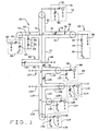
- FIG. 1 and 2 there is shown a circuit diagram of the multi-tuned NMR probe 20 of the present invention, configured for operation on six separate radio frequencies.
- a sample coil circuit 22, disposed within a magnet 24 and connected to an external transmission network 26 is employed to excite a sample 28 under analysis, detecting its magnetic resonance signature.
- the sample coil circuit 22 comprises a sample coil 30, connected between a coaxial line segment 32 of the transmission network 26 and electrical ground G. Connected in series between the sample coil 30 and the electrical ground G is a resistor 34 and fixed capacitor 36. To maintain a high degree of efficiency for the NMR probe, the magnitude of the resistor 34 corresponds to the inherent loss of the sample coil 30, as minimized through standard radio frequency techniques.
- the fixed capacitor 36 is used to provide an impedance for the sample coil 30, aiding in the tuning of individual probe frequencies.
- the optimum capacitance level for the fixed capacitor 36 is determined by analyzing the efficiency of the NMR probe 20 for each incorporated frequency, and selecting an optimum capacitance level resulting in the least amount of tuning interference over all the frequencies.
- a second fixed capacitor 38 is shown in Fig. 1 connected in parallel with the sample coil 30, between the segment 32 and electrical ground G.
- the fixed capacitor 38 represents the combination of the distributed capacitance and stray capacitance to ground of the sample coil 30.
- Radio frequency signals are transmitted to and from the sample coil circuit 22 by means of the transmission network 26.
- Each component of the transmission network 26 is a coaxial transmission line segment, having a length specifically selected to provide an impedance match for an individually tuned radio frequency.
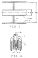
- Each coaxial transmission line comprises an inner tubular conductor 40 and outer tubular conductor 42, (Fig. 3) structured such that the ratio of the inner diameter IDOC of the outer conductor 42 to the outer diameter ODIC of the inner conductor 40 is approximately 3.59:1.
- the coaxial transmission lines are preferably composed of a copper tubing or pipes, which are essentially air dielectric since the inner conductor 40 is supported at a few points with Teflon® discs 44.
- the inner diameter of the outer coaxial conductor 42 must be of sufficient size so as to allow for the conventional tuning and coupling circuits described generally below to be located within the outer conductor 42.
- the preferred embodiment of the NMR probe 20 employs outer conductors 42 having a large outer diameters on the order of 5.08 cm (2 inches) or more to increase the NMR probe 20 efficiency and to reduce the electrical resistance of the transmission network 26.
- segment 32 connects the sample coil circuit 22 to the transmission network 26.
- the length L1 of segment 32 is calculated from standard transmission line equations using the value of the terminating impedance of the sample coil circuit 22 and the parameters of the transmission network 26 itself, such as radial dimensions, and composition. In practice, once the theoretical length of segment 32 is calculated, the exact length L1 is determined using standard radio frequency measurement techniques.
- a variable capacitor 46 is added internally to the segment 32, connecting the inner conductor 40 to the outer conductor 42 at a point of high impedance. The variable capacitor 46 is then tuned to adjust the signal impedance of the segment 32 such that a point of minimum impedance for the highest tuned frequency of the NMR probe 20 is exactly positioned at a junction point A in the transmission network 26.
- the highest frequency tuned by the present embodiment of the NMR probe 20 is the proton frequency of 500 MHz.
- points of minimum impedance for particular radio-frequencies on coaxial transmission lines repeat every one-half wavelength.
- the first occurrence of the minimum impedance point for the highest tuned frequency it is possible for the first occurrence of the minimum impedance point for the highest tuned frequency to be physically present within the bore 48 of the probe magnet 24, preventing its use as a junction point. In such situations, the first point of minimum impedance occurring external to the magnet bore 48 is employed as an alternate junction point.
- junction point A is positioned at the third minimum impedance point for the proton frequencies along segment 32.
- segment 32 Interconnected to segment 32 and the sample coil circuit 22 at junction point A, are coaxial transmission line segments 50, 52, and 54, each impedance matched to one or more tuned radio frequencies.
- Coaxial transmission line segment 50 along with a shunt element 56 connects junction point A with a radio-frequency input-output (I/O) circuit 58 suitable for proton irradiation.
- the proton I/O circuit 58 comprises a 500 MHz input-output port 60 adapted to a characteristic impedance, for example, 50 ohms, connected in series with a conventional tuning and coupling circuits comprising a variable capacitor 62 and a grounded variable capacitor 64.
- the shunt element 56 is positioned a length L2 along segment 50, at junction point B, approximately a quarter wavelength of the fluorine frequency from junction point A. Shunt element 56 acts as a radio frequency trap for the fluorine frequency, creating a very low impedance at junction point B for the fluorine frequency, and at the same time presenting a high impedance to the proton frequency.
- the length L3 of shunt element 56 is slightly longer than a quarter wavelength at the fluorine frequency, permitting internal variable capacitors 66 and 68 to be adjusted to meet the desired impedance conditions described above.
- segment 50 is selected such that the length from junction point B to the proton I/O circuit 58 permits reasonable values for variable capacitor 62 and grounded variable capacitor 64 to be used to tune and match to the desired 50 ohm impedance.
- two fixed capacitors 70 and 72 each valued at about 10 pico-farads increase the overall efficiency of the low frequency channels by isolating them from the proton I/O circuit 58 and the fluorine trap 56.
- Capacitor 70 is positioned on the inner coaxial conductor 40 adjacent to junction point A, capacitor 72 is positioned adjacent junction point B.
- coaxial transmission line segment 52 provides a connection between the transmission network 26 and a radio frequency input-output circuit 74 suitable for fluorine irradiation.
- the fluorine I/O circuit 74 comprises a 470 MHz input-output port 76 adapted to a characteristic impedance, for example, 50 ohms, connected in series with a conventional tuning and coupling circuit comprising a variable capacitor 78 and a grounded variable capacitor 80.
- the length L5 of segment 52 is selected such that it provides an impedance transformation of the impedance into segment 52 from junction point A, where it is capacitive, to the fluorine I/O circuit 74 to where it is inductive, and hence may be tuned and matched by reasonable values for capacitors 78 and 80.
- junction Point A The remaining coaxial transmission line segment connected to Junction Point A is segment 54, which serves as a connection link from the lower radio frequency channels to the sample coil circuit 22 via segment 32.
- the input impedance from junction point A to segment 54 must be high at the fluorine frequency to prevent fluorine signal power from being drained into segment 54, reducing the efficiency of the fluorine I/O circuit 74.
- the length L6 of segment 54, terminating at junction point C is a quarter wavelength at the fluorine frequency. Additionally, junction point C is maintained at a low impedance to the fluorine frequency by a shunt element 82 connected at junction point C.
- Shunt element 82 is a coaxial transmission line segment with a length L7 slightly less than a quarter wavelength at the fluorine frequency, and containing a variable capacitor 84 interconnecting the inner conductor 40 with the outer conductor 42.
- the variable capacitor 84 is adjusted to create a minimum impedance at junction point C as set forth above.
- junction point C is connected to junction point C and a fixed capacitor 88 connected to electrical ground G.
- the fixed capacitor 88 aids in maintaining the minimum impedance at junction point C, but is primarily used to tune the lower frequency channels connected to junction point C by segment 86.
- the capacitance of the fixed capacitor 88 affects the lengths of each subsequent coaxial transmission line segment used for lower radio frequencies in the transmission network 26.
- the length L8 of coaxial transmission line segment 86, terminating at junction point D, is selected to produce a minimum impedance at junction point D for the next lower radio frequency tuned on the NMR probe 20.
- a variable capacitor 90 contained within segment 86 permits the location of the next impedance minimum point to be electronically adjusted to a fine degree of precision along the length L8 of segment 86.
- the next lower radio frequency corresponds to that of phosphorous.
- a coaxial transmission line segment 92 provides a connection between junction point D on the transmission network 26 and a radio frequency input-output circuit 94 suitable for phosphorous irradiation.
- the phosphorous I/O circuit 94 comprises a 202 MHz input-output port 96 adapted to a characteristic impedance, for example, 50 ohms, connected in series witn a conventional tuning and coupling circuit comprising a variable capacitor 98 and a grounded variable capacitor 100.
- the length L9 of segment 92 is selected such that the impedance minimum for phosphorus at junction point D is transformed into an inductive impedance which can then be tuned and matched by reasonable values for the variable capacitors 98 and 100.
- junction point D is connected to junction point D and a fixed capacitor 104 connected to electrical ground.
- the fixed capacitor 104 aids in maintaining the minimum impedance at junction point D, but is primarily used to tune the lower frequency channels connected to junction point D by segment 102, much the same as fixed capacitor 88 tunes junction point C.
- the capacitance of fixed capacitor 104 similarly affects the lengths of each subsequent coaxial transmission line segment for lower radio frequencies in the transmission network 26.
- the length L10 of coaxial transmission line segment 102, terminating at junction point E, is selected to produce a minimum impedance at junction point E for the next lower radio frequency tuned on the NMR probe 20.
- a variable capacitor 106 contained within segment 102 permits the location of the next impedance minimum point to the electronically adjusted to a fine degree of precision along the length L10 of segment 102.
- the next lower radio frequency corresponds to that of carbon-13.
- a coaxial transmission line segment 108 provides a connection between junction point E on the transmission network 26 and a radio frequency input-output circuit 110 suitable for carbon-13 irradiation.
- the carbon-13 I/O circuit 110 comprises a 125 MHz input-output port 112 adapted to a characteristic impedance, for example, 50 ohms, connected in series with a conventional tuning and coupling circuit comprising a variable capacitor 114 and a grounded variable capacitor 116.
- the length L11 of segment 108 is selected such that the impedance minimum for carbon-13 at junction point E is transformed into an inductive impedance which can then be tuned and matched by reasonable values for the variable capacitors 114 and 116.
- junction point E is connected to junction point E.
- the fixed capacitor 120 aids in maintaining the minimum impedance at junction point E, but is primarily used to tune the lower frequency channels connected to junction point E by segment 118, much the same as fixed capacitor 104 tunes junction point D.
- the capacitance of fixed capacitor 120 affects the lengths of each subsequent coaxial transmission line segment for lower radio frequencies in the transmission network 26.
- the length L12 of coaxial transmission line segment 118, terminating at junction point F, is selected to produce a minimum impedance at junction point F for the next radio frequency tuned on the NMR probe 20.
- the next radio frequency corresponds to that of nitrogen-15. This is an example where the frequency of the next channel to add is not the next lowest frequency but is the next occurring impedance minima.
- a coaxial transmission line segment 122 provides a connection between junction point F on the transmission network 26 and a radio frequency input-output circuit 124 suitable for nitrogen-15 irradiation.
- the nitrogen-15 I/O circuit 124 comprises a 50 MHz input-output port 126 adapted to a characteristic impedance, for example, 50 ohms, connected in series with a conventional tuning and coupling circuit comprising a variable capacitor 128 and a grounded variable capacitor 130.
- the length L13 of segment 122 is selected such that the impedance minimum for nitrogen-15 at junction point F is transformed into an inductive impedance which can then be tuned and matched by reasonable values for the variable capacitors 128 and 130.
- a final coaxial transmission line segment 132 is connected to junction point F to provide connection to a radio frequency input-output circuit 134 suitable for oxygen-17 irradiation at 67.78 MHz, through a radio frequency I/O port 136.
- the length L14 of segment 132 is selected such that the variable capacitor 138, and the grounded variable capacitor 140 may be tuned and matched to provide a 50 ohm characteristic impedance match for the oxygen-17 I/O circuit 134.
- embodiments of the present invention may be constructed employing many different NMR frequencies by altering the quantity and impedance characteristics of the individual radio-frequency input-output means and the associated coaxial transmission line segment lengths.
- any channel or channels added may be changed to another frequency which is also lower than the channels iocated above it without altering the higher frequency channel settings. This makes possible, for example, the insertion of another group of nuclei for lower frequency channels at junction point E without altering the characteristics at junction points A-D.
- an embodiment of the present invention may be constructed suitable for Deuterium irradiation by altering the 67.78 MHz input-output port 136 to a 76.75 MHz input-output port.
- the length L14 of transmission line segment 132 would be recalculated to provide for the proper impedance matching by variable capacitors 138 and 140 as described above.
Landscapes
- Physics & Mathematics (AREA)
- Condensed Matter Physics & Semiconductors (AREA)
- General Physics & Mathematics (AREA)
- Magnetic Resonance Imaging Apparatus (AREA)
Claims (18)
- Sonde à bobine unique (20) du type à syntonisation multiple pour un spectromètre à résonance magnétique nucléaire, ladite sonde comprenant :un réseau de ligne coaxiale (26), le réseau englobant un conducteur électrique externe (42) et un conducteur électrique interne coaxial (40) ;une bobine d'exploration unique (30) pour des radiofréquences, ladite bobine (30) étant couplée électriquement audit réseau de ligne coaxiale (26) à un premier endroit de jonction (A) dudit réseau au moyen d'un premier segment de ligne de connexion coaxiale (32) ;et une multitude de connecteurs de type entrée/sortie du type à radiofréquences (60, 76, 96, 112, 126, 136) ;un premier connecteur de type entrée/sortie (60) muni d'un premier circuit de syntonisation (58) de type capacitif adapté de manière unique à une première fréquence de résonance, par exemple celle de protons, et couplé électriquement via un deuxième segment de ligne de connexion coaxiale (50) au premier endroit de jonction (A) du réseau de ligne coaxiale, le premier endroit de jonction (A) possédant une impédance minimale pour la première fréquence de résonance le long du premier segment de ligne de connexion coaxiale (32), la longueur du deuxième segment de ligne de connexion coaxiale (50) étant telle qu'elle procure une transformation d'impédance pour passer de l'impédance minimale en vigueur au premier endroit de jonction (A) à une impédance inductive pour la première fréquence audit premier circuit de syntonisation (58) de type capacitif ;le deuxième segment de ligne de connexion coaxiale (50) procurant un deuxième endroit de jonction (B) pour connecter un premier circuit réjecteur de radiofréquences (56) pour une deuxième fréquence de résonance, par exemple celle du fluor, inférieure à la première fréquence de résonance, pour ainsi obtenir une impédance élevée pour la deuxième fréquence de résonance au premier endroit de jonction (A) en direction dudit deuxième segment de ligne de connexion coaxiale (50) ;un deuxième connecteur de type entrée/sortie (76) muni d'un deuxième circuit de syntonisation (74) de type capacitif adapté de manière unique à la deuxième fréquence de résonance et couplé électriquement via un troisième segment de ligne de connexion coaxiale (52) au premier endroit de jonction (A) du réseau de ligne coaxiale, la longueur du troisième segment de ligne de connexion coaxiale (52) étant telle qu'elle procure une transformation d'impédance pour passer de l'impédance capacitive en vigueur au premier endroit de jonction (A) à une impédance inductive pour la deuxième fréquence de résonance audit deuxième circuit de syntonisation (74) de type capacitif ;un premier segment de ligne coaxiale (54) dudit réseau de ligne de transmission prévu entre le premier endroit de jonction (A) et un troisième endroit de jonction (C), la longueur du premier segment (54) étant telle que l'impédance d'entrée depuis le premier endroit de jonction (A) jusqu'audit premier segment (54) est haute à la deuxième fréquence de résonance, un deuxième circuit réjecteur de radiofréquences (82) pour la deuxième fréquence de résonance étant relié au troisième endroit de jonction (C) pour procurer une impédance minimale pour la deuxième fréquence de résonance au troisième endroit de jonction (C) ;un deuxième segment de ligne coaxiale (86) dudit réseau de ligne de transmission prévu entre le troisième endroit de jonction (C) et un quatrième endroit de jonction (D), la longueur dudit deuxième segment (86) étant telle qu'elle fournit une impédance minimale pour une troisième fréquence de résonance, par exemple celle du phosphore, inférieure à celle de la deuxième fréquence de résonance, au quatrième endroit de jonction (D) ;un troisième connecteur de type entrée/sortie (96) muni d'un troisième circuit de syntonisation (94) de type capacitif adapté de manière unique à la troisième fréquence de résonance et couplé électriquement via un quatrième segment de ligne de connexion coaxiale (92) au quatrième endroit de jonction (D) du réseau de ligne de transmission, la longueur dudit quatrième segment de ligne de connexion coaxiale (92) étant telle qu'elle procure une transformation d'impédance pour passer de l'impédance minimale en vigueur au quatrième endroit de jonction (D) à une impédance inductive pour la troisième fréquence de résonance audit troisième circuit de syntonisation (94) de type capacitif ;le réseau de ligne de transmission étant de type modulaire de telle sorte que l'on peut coupler au réseau des canaux supplémentaires pour des fréquences de résonance ultérieures, inférieures aux fréquences de résonance définies ci-dessus, après le quatrième endroit de jonction (D) d'une manière similaire au troisième connecteur de type entrée/sortie, sans modifier les caractéristiques en vigueur au quatrième endroit de jonction et aux endroits de jonction précédents.
- Sonde selon la revendication 1, dans laquelle chacun desdits circuit de syntonisation de type capacitif est disposé à distance de ladite bobine d'exploration et du champ magnétique dudit spectromètre.
- Sonde selon la revendication 1, dans laquelle chacun desdits circuits de syntonisation de type capacitif englobe un condensateur variable monté en série et un condensateur variable mis à la terre.
- Sonde selon la revendication 3, dans laquelle chacun desdits circuits de syntonisation de type capacitif est confiné à l'intérieur du conducteur électrique externe dudit réseau de ligne coaxiale.
- Sonde selon la revendication 3, dans laquelle lesdits circuits de syntonisation de type capacitif sont en mesure de régler lesdites radiofréquences d'entrée/sortie à concurrence de 1 à 2 %.
- Sonde selon la revendication 1, dans laquelle lesdits conducteurs électriques interne et externe du réseau de ligne coaxiale sont composés de tubes conducteurs cylindriques, le rapport du diamètre interne du tube conducteur externe au diamètre externe du tube conducteur interne s'élevant approximativement à 3,59 : 1.
- Sonde selon la revendication 6, dans laquelle ledit tube conducteur externe possède un diamètre externe supérieur à 5,08 cm (deux pouces).
- Sonde selon la revendication 6, dans laquelle lesdits tubes conducteurs interne et externe sont réalisés en un matériau très conducteur.
- Sonde selon la revendication 8, dans laquelle lesdits tubes conducteurs interne et externe sont réalisés en cuivre.
- Sonde selon la revendication 6, dans laquelle ledit réseau de ligne coaxiale contient un diélectrique à faibles pertes.
- Sonde selon la revendication 10, dans laquelle ledit diélectrique à faibles pertes est l'air.
- Sonde selon la revendication 1, dans laquelle lesdites fréquences de résonance sont séparées par des différences qui ne sont pas inférieures à 6 %.
- Sonde selon la revendication 1, dans laquelle lesdites fréquences de résonance se situent dans la plage de 50 MHz à 500 MHz.
- Sonde selon la revendication 1, dans laquelle lesdits plusieurs connecteurs entrée/sortie du type à radiofréquences englobent :un connecteur entrée/sortie du type à radiofréquence conçu pour la fréquence radio de protons d'approximativement 500,0 MHz ;un connecteur entrée/sortie du type à radiofréquence conçu pour la fréquence radio du fluor d'approximativement 470,0 MHz ;un connecteur entrée/sortie du type à radiofréquence conçu pour la fréquence radio du phosphore d'approximativement 202,0 MHz ;un connecteur entrée/sortie du type à radiofréquence conçu pour la fréquence radio du carbone 13 d'approximativement 125,0 MHz ; etun connecteur entrée/sortie du type à radiofréquence conçu pour la fréquence radio de l'azote 15 d'approximativement 50,0 MHz.
- Sonde selon la revendication 14, dans laquelle lesdits plusieurs connecteurs entrée/sortie du type à radiofréquences englobent en outre un connecteur entrée/sortie du type à radiofréquences conçu pour la fréquence radio du deutérium d'approximativement 76,75 MHz.
- Sonde selon la revendication 14, dans laquelle lesdits plusieurs connecteurs entrée/sortie du type à radiofréquences englobent en outre un connecteur entrée/sortie du type à radiofréquences conçu pour la fréquence radio de l'oxygène 17 d'approximativement 67,78 MHz.
- Sonde selon la revendication 1, dans laquelle le réseau de ligne coaxial englobe en outre plusieurs éléments de syntonisation de type capacitif reliant les conducteurs électriques interne et externe les uns aux autres, lesdits éléments de syntonisation de type capacitif affectant la localisation desdits endroits d'impédance minimale.
- Sonde selon la revendication 17, dans laquelle des éléments de syntonisation d'interconnexion sont des condensateurs variables.
Applications Claiming Priority (2)
| Application Number | Priority Date | Filing Date | Title |
|---|---|---|---|
| US08/889,922 US5861748A (en) | 1997-07-10 | 1997-07-10 | Multi-tuned single coil transmission line probe for nuclear magnetic resonance spectrometer |
| US889922 | 1997-07-10 |
Publications (2)
| Publication Number | Publication Date |
|---|---|
| EP0890848A1 EP0890848A1 (fr) | 1999-01-13 |
| EP0890848B1 true EP0890848B1 (fr) | 2005-06-01 |
Family
ID=25395995
Family Applications (1)
| Application Number | Title | Priority Date | Filing Date |
|---|---|---|---|
| EP98630034A Expired - Lifetime EP0890848B1 (fr) | 1997-07-10 | 1998-07-03 | Sonde pour un spectromètre de résonance magnétique nucléaire comprenant une bobine unique réglée sur plusieurs fréquences à l'aide d'un réseau de lignes de transmission |
Country Status (5)
| Country | Link |
|---|---|
| US (1) | US5861748A (fr) |
| EP (1) | EP0890848B1 (fr) |
| JP (1) | JPH1172547A (fr) |
| AT (1) | ATE297020T1 (fr) |
| DE (1) | DE69830363D1 (fr) |
Families Citing this family (13)
| Publication number | Priority date | Publication date | Assignee | Title |
|---|---|---|---|---|
| US6081120A (en) * | 1998-05-20 | 2000-06-27 | Shen; Gary G | Universal-multi-layered, multi-tuned RF probe for MRI and MRS |
| DE19923294C1 (de) * | 1999-05-21 | 2001-02-15 | Bruker Analytik Gmbh | Probenkopf für Kernresonanzmessungen |
| DE10019990C2 (de) * | 2000-04-22 | 2002-04-04 | Bruker Analytik Gmbh | Probenkopf für Kernresonanzmessungen |
| JP3886764B2 (ja) * | 2001-04-10 | 2007-02-28 | 日本電子株式会社 | 核磁気共鳴装置の複同調回路およびプローブ |
| WO2003058283A1 (fr) * | 2001-12-31 | 2003-07-17 | The Johns Hopkins University School Of Medicine | Antenne accordable et systeme pour irm |
| JP2005520658A (ja) | 2002-03-21 | 2005-07-14 | コーニンクレッカ フィリップス エレクトロニクス エヌ ヴィ | Mriシステムに対するコンバイナ/スプリッタ装置 |
| FR2871892B1 (fr) * | 2004-06-18 | 2006-09-01 | Bruker Biospin Sa Sa | Circuit d'alimentation d'une bobine et sonde et spectrometre rmn comportant un tel circuit |
| FR2871891B1 (fr) * | 2004-06-18 | 2006-09-01 | Bruker Biospin Sa Sa | Circuit d'alimentation multifrequencielle et sonde et spectrometre rmn comportant un tel circuit |
| US7187176B2 (en) * | 2005-02-08 | 2007-03-06 | Bruker Biospin Corp. | NMR probe circuit with nodal impedance bridge |
| DE102006030640B4 (de) * | 2005-07-15 | 2018-05-09 | Jeol Ltd. | Kernspinresonanz-Sonde |
| US7352185B1 (en) * | 2006-11-22 | 2008-04-01 | Varian, Inc. | Multi-functional NMR probe |
| US9829550B2 (en) * | 2012-12-27 | 2017-11-28 | General Electric Company | Multi-nuclear receiving coils for magnetic resonance imaging (MRI) |
| CA3054684A1 (fr) | 2017-03-01 | 2018-09-07 | Scanmed, Llc | Resonateur irm a double syntonisation, assemblage de bobines et procede |
Family Cites Families (16)
| Publication number | Priority date | Publication date | Assignee | Title |
|---|---|---|---|---|
| US2908858A (en) * | 1952-08-08 | 1959-10-13 | Varian Associates | Decoupling means for electrical circuits |
| US3372331A (en) * | 1965-01-25 | 1968-03-05 | Varian Associates | Gyromagnetic spectrometer having a tapered dielectric transition between a coaxial line and a helix structure |
| US3434043A (en) * | 1966-02-14 | 1969-03-18 | Varian Associates | Nuclear magnetic resonance probe apparatus having double tuned coil systems for spectrometers employing an internal reference |
| US3402346A (en) * | 1966-04-22 | 1968-09-17 | Varian Associates | Coaxial receiver coil and capacitor structure for probes of uhf gyromagnetic spectrometers |
| US3795855A (en) * | 1971-12-08 | 1974-03-05 | Cyclotron Corp | Magnetic resonance probe system |
| US3858112A (en) * | 1973-09-20 | 1974-12-31 | Nippon Electric Varian Ltd | A receiver circuit including a crystal resonator for nuclear magnetic resonance signals of two different frequencies |
| GB1544272A (en) * | 1975-02-04 | 1979-04-19 | Jeol Ltd | Nuclear magnetic resonance apparatus |
| US4129822A (en) * | 1975-04-24 | 1978-12-12 | Traficante D | Wide-band nuclear magnetic resonance spectrometer |
| US4093910A (en) * | 1977-02-22 | 1978-06-06 | Varian Associates, Inc. | Nuclear magnetic resonance pick-up circuit for control of resonance conditions |
| US4093911A (en) * | 1977-02-22 | 1978-06-06 | Varian Associates, Inc. | Nuclear magnetic resonance spectrometer employing an improved resonance signal gating circuit |
| US4095168A (en) * | 1977-02-22 | 1978-06-13 | Varian Associates, Inc. | Rf pick-up coil circuit for a wide tuning range nuclear magnetic resonance probe |
| US4446431A (en) * | 1981-08-24 | 1984-05-01 | Monsanto Company | Double-tuned single coil probe for nuclear magnetic resonance spectrometer |
| US4792759A (en) * | 1987-07-29 | 1988-12-20 | Elscint Ltd. | Multi-frequency surface probe |
| JPH01293858A (ja) * | 1988-05-20 | 1989-11-27 | Toshiba Corp | Rfコイル装置 |
| US5675254A (en) * | 1993-06-02 | 1997-10-07 | The Board Of Trustees Of The University Of Illinois | Double-resonance MRI coil |
| JP3773537B2 (ja) * | 1995-11-14 | 2006-05-10 | コーニンクレッカ フィリップス エレクトロニクス エヌ ヴィ | 磁気共鳴装置用の同軸ケーブル |
-
1997
- 1997-07-10 US US08/889,922 patent/US5861748A/en not_active Expired - Lifetime
-
1998
- 1998-07-03 DE DE69830363T patent/DE69830363D1/de not_active Expired - Lifetime
- 1998-07-03 AT AT98630034T patent/ATE297020T1/de not_active IP Right Cessation
- 1998-07-03 EP EP98630034A patent/EP0890848B1/fr not_active Expired - Lifetime
- 1998-07-10 JP JP10195340A patent/JPH1172547A/ja active Pending
Also Published As
| Publication number | Publication date |
|---|---|
| EP0890848A1 (fr) | 1999-01-13 |
| DE69830363D1 (de) | 2005-07-07 |
| JPH1172547A (ja) | 1999-03-16 |
| US5861748A (en) | 1999-01-19 |
| ATE297020T1 (de) | 2005-06-15 |
Similar Documents
| Publication | Publication Date | Title |
|---|---|---|
| EP0890848B1 (fr) | Sonde pour un spectromètre de résonance magnétique nucléaire comprenant une bobine unique réglée sur plusieurs fréquences à l'aide d'un réseau de lignes de transmission | |
| KR890000411B1 (ko) | Nmr 주사장치 | |
| US4887039A (en) | Method for providing multiple coaxial cable connections to a radio-frequency antenna without baluns | |
| US4691163A (en) | Dual frequency surface probes | |
| EP0073614B1 (fr) | Capteur à bobine simple à accord double pour un spectromètre à résonance magnétique nucléaire | |
| US6933725B2 (en) | NMR probe circuit for generating close frequency resonances | |
| US5424645A (en) | Doubly broadband triple resonance or quad resonance NMR probe circuit | |
| US4987370A (en) | Rf quadrature coil system for an MRI apparatus | |
| JP2748016B2 (ja) | 分散集中静電容量観察コイル用二重同調回路 | |
| JP2904858B2 (ja) | 核磁気共鳴断層撮影装置 | |
| EP0518896B1 (fr) | Bobines de resonance magnetique nucleaire en serie/paralleles a double syntonisation | |
| US5166621A (en) | Multi-resonant nmr coils | |
| US5162739A (en) | Balanced multi-tuned high-power broadband coil for nmr | |
| EP1710596B1 (fr) | Circuit de sonde RMN avec pont d'impédance nodal | |
| Gonord et al. | Parallel‐plate split‐conductor surface coil: Analysis and design | |
| EP0165741A2 (fr) | Cavité comportant deux barres rentrantes pour sondes de résonance magnétique nucléaire | |
| US6175237B1 (en) | Center-fed paralleled coils for MRI | |
| EP0579473B1 (fr) | Sonde RF accordable utilisée dans des expériences de spectroscopie RMN et procédé d'accordage | |
| JP3914735B2 (ja) | 多重共鳴用nmrプローブ | |
| Brondeau et al. | Flexible Fourier multinuclear magnetic resonance spectrometer | |
| Stensgaard | Planar quadrature coil design using shielded-loop resonators | |
| JPH10314139A (ja) | 磁気共鳴イメージング装置 | |
| JP4156646B2 (ja) | 多重共鳴用nmrプローブ | |
| Tang et al. | Double-resonance circuit for nuclear magnetic resonance spectroscopy | |
| CA2244847C (fr) | Bobines paralleles a alimentation centrale pour imagerie rmn |
Legal Events
| Date | Code | Title | Description |
|---|---|---|---|
| PUAI | Public reference made under article 153(3) epc to a published international application that has entered the european phase |
Free format text: ORIGINAL CODE: 0009012 |
|
| AK | Designated contracting states |
Kind code of ref document: A1 Designated state(s): AT BE CH CY DE DK ES FI FR GB GR IE IT LI LU MC NL PT SE |
|
| AX | Request for extension of the european patent |
Free format text: AL;LT;LV;MK;RO;SI |
|
| 17P | Request for examination filed |
Effective date: 19990205 |
|
| AKX | Designation fees paid |
Free format text: AT BE CH CY DE DK ES FI FR GB GR IE IT LI LU MC NL PT SE |
|
| 17Q | First examination report despatched |
Effective date: 20040128 |
|
| GRAP | Despatch of communication of intention to grant a patent |
Free format text: ORIGINAL CODE: EPIDOSNIGR1 |
|
| GRAS | Grant fee paid |
Free format text: ORIGINAL CODE: EPIDOSNIGR3 |
|
| GRAA | (expected) grant |
Free format text: ORIGINAL CODE: 0009210 |
|
| AK | Designated contracting states |
Kind code of ref document: B1 Designated state(s): AT BE CH CY DE DK ES FI FR GB GR IE IT LI LU MC NL PT SE |
|
| PG25 | Lapsed in a contracting state [announced via postgrant information from national office to epo] |
Ref country code: NL Free format text: LAPSE BECAUSE OF FAILURE TO SUBMIT A TRANSLATION OF THE DESCRIPTION OR TO PAY THE FEE WITHIN THE PRESCRIBED TIME-LIMIT Effective date: 20050601 Ref country code: LI Free format text: LAPSE BECAUSE OF FAILURE TO SUBMIT A TRANSLATION OF THE DESCRIPTION OR TO PAY THE FEE WITHIN THE PRESCRIBED TIME-LIMIT Effective date: 20050601 Ref country code: IT Free format text: LAPSE BECAUSE OF FAILURE TO SUBMIT A TRANSLATION OF THE DESCRIPTION OR TO PAY THE FEE WITHIN THE PRE;WARNING: LAPSES OF ITALIAN PATENTS WITH EFFECTIVE DATE BEFORE 2007 MAY HAVE OCCURRED AT ANY TIME BEFORE 2007. THE CORRECT EFFECTIVE DATE MAY BE DIFFERENT FROM THE ONE RECORDED.SCRIBED TIME-LIMIT Effective date: 20050601 Ref country code: FI Free format text: LAPSE BECAUSE OF FAILURE TO SUBMIT A TRANSLATION OF THE DESCRIPTION OR TO PAY THE FEE WITHIN THE PRESCRIBED TIME-LIMIT Effective date: 20050601 Ref country code: ES Free format text: LAPSE BECAUSE OF FAILURE TO SUBMIT A TRANSLATION OF THE DESCRIPTION OR TO PAY THE FEE WITHIN THE PRESCRIBED TIME-LIMIT Effective date: 20050601 Ref country code: CH Free format text: LAPSE BECAUSE OF FAILURE TO SUBMIT A TRANSLATION OF THE DESCRIPTION OR TO PAY THE FEE WITHIN THE PRESCRIBED TIME-LIMIT Effective date: 20050601 Ref country code: BE Free format text: LAPSE BECAUSE OF FAILURE TO SUBMIT A TRANSLATION OF THE DESCRIPTION OR TO PAY THE FEE WITHIN THE PRESCRIBED TIME-LIMIT Effective date: 20050601 Ref country code: AT Free format text: LAPSE BECAUSE OF FAILURE TO SUBMIT A TRANSLATION OF THE DESCRIPTION OR TO PAY THE FEE WITHIN THE PRESCRIBED TIME-LIMIT Effective date: 20050601 |
|
| REG | Reference to a national code |
Ref country code: GB Ref legal event code: FG4D |
|
| REG | Reference to a national code |
Ref country code: CH Ref legal event code: EP |
|
| REG | Reference to a national code |
Ref country code: IE Ref legal event code: FG4D |
|
| PG25 | Lapsed in a contracting state [announced via postgrant information from national office to epo] |
Ref country code: LU Free format text: LAPSE BECAUSE OF NON-PAYMENT OF DUE FEES Effective date: 20050703 Ref country code: CY Free format text: LAPSE BECAUSE OF FAILURE TO SUBMIT A TRANSLATION OF THE DESCRIPTION OR TO PAY THE FEE WITHIN THE PRESCRIBED TIME-LIMIT Effective date: 20050703 |
|
| PG25 | Lapsed in a contracting state [announced via postgrant information from national office to epo] |
Ref country code: IE Free format text: LAPSE BECAUSE OF NON-PAYMENT OF DUE FEES Effective date: 20050704 |
|
| REF | Corresponds to: |
Ref document number: 69830363 Country of ref document: DE Date of ref document: 20050707 Kind code of ref document: P |
|
| PG25 | Lapsed in a contracting state [announced via postgrant information from national office to epo] |
Ref country code: MC Free format text: LAPSE BECAUSE OF NON-PAYMENT OF DUE FEES Effective date: 20050731 |
|
| PG25 | Lapsed in a contracting state [announced via postgrant information from national office to epo] |
Ref country code: SE Free format text: LAPSE BECAUSE OF FAILURE TO SUBMIT A TRANSLATION OF THE DESCRIPTION OR TO PAY THE FEE WITHIN THE PRESCRIBED TIME-LIMIT Effective date: 20050901 Ref country code: GR Free format text: LAPSE BECAUSE OF FAILURE TO SUBMIT A TRANSLATION OF THE DESCRIPTION OR TO PAY THE FEE WITHIN THE PRESCRIBED TIME-LIMIT Effective date: 20050901 Ref country code: GB Free format text: LAPSE BECAUSE OF NON-PAYMENT OF DUE FEES Effective date: 20050901 Ref country code: DK Free format text: LAPSE BECAUSE OF FAILURE TO SUBMIT A TRANSLATION OF THE DESCRIPTION OR TO PAY THE FEE WITHIN THE PRESCRIBED TIME-LIMIT Effective date: 20050901 |
|
| PG25 | Lapsed in a contracting state [announced via postgrant information from national office to epo] |
Ref country code: DE Free format text: LAPSE BECAUSE OF FAILURE TO SUBMIT A TRANSLATION OF THE DESCRIPTION OR TO PAY THE FEE WITHIN THE PRESCRIBED TIME-LIMIT Effective date: 20050902 |
|
| PG25 | Lapsed in a contracting state [announced via postgrant information from national office to epo] |
Ref country code: PT Free format text: LAPSE BECAUSE OF FAILURE TO SUBMIT A TRANSLATION OF THE DESCRIPTION OR TO PAY THE FEE WITHIN THE PRESCRIBED TIME-LIMIT Effective date: 20051103 |
|
| NLV1 | Nl: lapsed or annulled due to failure to fulfill the requirements of art. 29p and 29m of the patents act | ||
| REG | Reference to a national code |
Ref country code: CH Ref legal event code: PL |
|
| PLBE | No opposition filed within time limit |
Free format text: ORIGINAL CODE: 0009261 |
|
| STAA | Information on the status of an ep patent application or granted ep patent |
Free format text: STATUS: NO OPPOSITION FILED WITHIN TIME LIMIT |
|
| REG | Reference to a national code |
Ref country code: IE Ref legal event code: MM4A |
|
| 26N | No opposition filed |
Effective date: 20060302 |
|
| GBPC | Gb: european patent ceased through non-payment of renewal fee |
Effective date: 20050901 |
|
| EN | Fr: translation not filed | ||
| PG25 | Lapsed in a contracting state [announced via postgrant information from national office to epo] |
Ref country code: FR Free format text: LAPSE BECAUSE OF NON-PAYMENT OF DUE FEES Effective date: 20050731 |
|
| PG25 | Lapsed in a contracting state [announced via postgrant information from national office to epo] |
Ref country code: FR Free format text: LAPSE BECAUSE OF NON-PAYMENT OF DUE FEES Effective date: 20050601 |