EP0890852A2 - Dispositif blind de soudage pour fibres optiques - Google Patents
Dispositif blind de soudage pour fibres optiques Download PDFInfo
- Publication number
- EP0890852A2 EP0890852A2 EP98850082A EP98850082A EP0890852A2 EP 0890852 A2 EP0890852 A2 EP 0890852A2 EP 98850082 A EP98850082 A EP 98850082A EP 98850082 A EP98850082 A EP 98850082A EP 0890852 A2 EP0890852 A2 EP 0890852A2
- Authority
- EP
- European Patent Office
- Prior art keywords
- casing
- fibers
- welding location
- welding
- optical fibers
- Prior art date
- Legal status (The legal status is an assumption and is not a legal conclusion. Google has not performed a legal analysis and makes no representation as to the accuracy of the status listed.)
- Granted
Links
Images
Classifications
-
- G—PHYSICS
- G02—OPTICS
- G02B—OPTICAL ELEMENTS, SYSTEMS OR APPARATUS
- G02B6/00—Light guides; Structural details of arrangements comprising light guides and other optical elements, e.g. couplings
- G02B6/24—Coupling light guides
- G02B6/255—Splicing of light guides, e.g. by fusion or bonding
- G02B6/2551—Splicing of light guides, e.g. by fusion or bonding using thermal methods, e.g. fusion welding by arc discharge, laser beam, plasma torch
Definitions
- the present invention relates to a fiber welding device for welding optical fibers to each other, in particular for welding optical fibers composed to a fiber ribbon to each other, and subassemblies used in a fiber welding device.
- optical fiber ribbons i.e. optical fibers, which by an exterior polymer sleeve are kept together to form a flat fiber package having a plurality of optical fibers extending in parallel, are more and more used.
- a fiber ribbon can contain 4, 6, 8 or 12 individual fibers.
- welding can be used.
- devices are required which can be used in the field.
- Such a welding device should among other things have a good shielding of the region around the splicing location, in which the very electrical arc is formed at the ends of the optical fibers, so that an operator of the welding device is well protected.
- a shielding would also protect this area against contamination from the surroundings.
- a number of different conditions must be fulfilled, such as that the individual optical fibers in the opposite ends of two fiber ribbons are well aligned with each other, that the alignment can be checked immediately before the welding operation and that the alignment then can possibly be corrected.
- a background illumination of the fiber ends to be spliced to each other should be provided in order to obtain pictures for checking the positions of opposite fiber ends.
- U.S. patent US-A 5,524,163 which corresponds to the published European patent application EP-A1 0 720 032, discloses a device and a method for splicing optical fibers.
- the device comprises a microscope unit, a light emitting diode holder placed above the fibers and a cover enclosing the light emitting diode retainer.
- the microscope unit consists of a housing, three microscopes, a shutter unit, two mirrors and a CCD-sensor.
- the light emitting diode retainer which comprises three light emitting diodes, is mounted to swing about the same shaft as the cover and is locked in a swung-down position by means of a magnet.
- a background illumination is obtained from the light emitting diodes directing light from above to the welding location. The light from the welding location is deflected by mirrors to reach a photodetector.
- the published International patent application WO-A1 96/27811 discloses an illumination of the welding location comprising a light source located under the horizontal plane through the welding location, the light from the light source being deflected by two mirrors placed in a lid of the device.
- An optical fiber welding device for welding fiber ribbons has a casing which is movable between a closed position and an open position. In the closed position the casing is located above and at the sides of the welding location and encloses at least in an upward direction, in a direction parallel to inserted fibers and in horizontal directions perpendicular to inserted fibers the welding location and also the components of the device which are located at the welding location such as electrodes and an electrode housing.
- the casing is made of thin plate-shaped or sheet material and has a space-saving design and in particular the movement thereof is space-saving, since the casing performs a sliding moving so that in its movement the surfaces of the casing are all the time all located in substantially the same contiguous and continuous surface.
- the surfaces of the casing then corresponds to a part of this continuous surface.
- the continuous surface preferably has a rotational symmetry about an axis.
- This axis is then also a rotational or swinging axis of the casing.
- the axis is located so that no part of the casing ever moves towards the head of an operator, which normally, when inserting and inspecting fibers, is located above the welding location.
- the inserted fibers are supported by some support and alignment means, such as a V-groove plate.
- the highest points of the casing will in its movements always have substantially the same height over the welding location, the term height being here taken to mean the distance from the welding location to the highest points in a direction perpendicular to the fiber portions at the welding location and away from the body of the welding device and support and alignment means of the fibers.
- the rotational axis of the casing will then preferably be located at a position below the welding position, at some distance from that position and for instance in parallel to the inserted fiber ends.
- the casing comprises two casing halves, which are mounted to swing around parallel shafts, the shafts being arranged at locations approximately vertically below the very welding location, at not too a small distance thereof.
- the casing halves which are mechanically coupled to each other through a mechanical coupling comprising cooperating gear segments and thereby simultaneously and symmetrically move towards and away from each other, also in the case where only one half is operated, protect in their closed positions exterior dust particles from reaching the welding location and protect the operator from the electric welding arc and high electric and magnetic fields and loose particles.
- the casings have a design which saves space and in their movement occupy a minimum of space, by the fact that they are designed as substantially sectors of the surface of a rotationally symmetric body such as a circular cylinder and by the fact that the rotational axes of the casings are placed at the points of the sectors, ordinarily very near each other.
- a hold-down mechanism comprising a single arm, which is mounted to be capable of a swinging movement and which has elastic hold-down surfaces at its exterior end distant from the swinging axis of the arm.
- the hold-down surface can be detached from the fibers also when the casing halves are in closed positions by operating levers, which facilitate in the case when the positions of the fibers in the V-grooves have to be adjusted.
- the frame furthermore openings are provided, in which separate camera units are placed.
- light emitting diodes are arranged, the light of which is reflected towards the welding location by mirrors attached to the inner sides of the casings.
- a casing for a fiber welding device can comprise two casing halves, which are configured substantially identically to each other and which are mounted to be capable of swinging around suitably placed shafts, so that the halves can move in directions towards each other in order to engage with each other, so that the region around the electrodes is closed, and in directions away from each other in order to make the same region accessible.
- the shapes of the casing and thus of the casing halves are such and in particular the shafts of the casing halves are located at such positions below the welding location, that the topmost point of the casing or casing halves at its/their movement between a closed position and an open position, i.e. for the casing halves in directions away from and towards each other, remains at a substantially constant height.
- a swinging shaft of the casing or the shafts of the casing halves are advantageously located at positions which are placed substantially straight below the welding location, at a distance below it, which can for example correspond to substantially half the width of the inner portions of the device, the width being taken in the same direction as the movement directions of the casing or casing halves, i.e. perpendicularly to the longitudinal direction of inserted fibers.
- An electrode housing is advantageously made as a single unit having means attached thereto for retaining electrodes and means for aligning and retaining fibers.
- the electrodes and the welding location are located at the top surface of the electrode housing. Then also the swinging shafts of the casings halves are located below the electrode housing.
- the casing halves can generally comprise flat side portions, which are perpendicular to the swinging shafts, and furthermore top portions, which connect the side portions at the exterior edges thereof and which comprise portions, which have the shape of a part of the envelope surface of a circular cylinder, where the axis of the cylinder coincides with the shaft of the respective casing half, i.e. a casing half can have the shape of substantially a sector of the exterior border surface of a circular-cylindrical body.
- the top portions can also comprise substantially flat inner portions, which in their position, in which the casing halves are arranged at each other, are located at each other in the same horizontal plane and at their edges at a distance from the border surface between the casings connect to the portions having a part-cylindrical shape. Sealings can then be arranged at a distance from the border plane of the casing halves, in the closed positions thereof, so that they are always engaged with those portions of the top portions, which have the shape of the envelope of a part of a cylinder, i.e. so that the distance is longer than the length of a flat portion of the top portions.
- the movements of the casing halves are furthermore advantageously mechanically coupled to each other using a suitable mechanical coupling, so that for manually operating a first casing half in order to move it in a direction towards or from a second casing half also the second half is moved in the corresponding way, in a direction towards or from the first casing half respectively.
- the mechanical coupling can then comprise gear segments engaging each other, which are arranged at vertical side portions of the casing halves, the axes of the segments coinciding with the swinging shafts of the casing halves.
- the device can comprise fiber alignment means such as V-grooves, hold-down means, which are movable between a down-folded position for retaining fibers in the fiber alignment means and a folded-up position for releasing fibers introduced in the alignment means and naturally electrodes connected to a high voltage source for forming an electric arc between the points thereof.
- Bringing-down means can then be coupled to the casing in order to operate, in the movement of the casing from an open to a closed position, the hold-down means, in the case where they are in folded-up position, in order to move them to the folded-down position.
- the bringing-down means advantageously comprise a rotatable wheel attached to a casing half, which in the movement of the casing half, from an open to a closed position, cooperates with a top surface of the hold-down means.
- the hold-down means can furthermore comprise a single hold-down arm, which is movable between a folded-down position for retaining fibers in the fiber alignment means and a folded-up position for releasing introduced fibers, where the swinging shaft of the arm is parallel to the longitudinal direction of introduced fibers and in approximately the same horizontal plane as the fibers.
- the hold-down means can comprise hold-down units, which are movably arranged at the end of the hold-down arm and which are elastically biassed to contact the top side or surface of fibers inserted in the alignment means, when the hold-down arm is in its folded-down position, and to then press in a direction perpendicularly to inserted fibers and in a direction towards the alignment means in order to retain the fibers therein.
- the hold-down units advantageously comprise two hold-down elements, which are individually movable and which each acts on fibers on only one side of the welding location.
- the hold-down units are thus movable in a direction perpendicular to inserted fibers and then releasing means can be arranged for lifting, when these releasing means are operated, the hold-down units, all of the hold-down arm still maintaining the same folded-down position so that fibers inserted in the aligning means are released from the alignment means and the position thereof can be adjusted.
- the releasing means can comprise a lever, which is movably mounted at a casing half and which has an upper end, which is accessible from the exterior side of that casing half and can be operated therefrom. This design facilitates the exact introduction of the fibers in the V-grooves.
- Light sources can advantageously be arranged in order to provide a background illumination of the ends of the fibers at the welding location and then mirrors can be provided at the interior side of the casing for deflecting light from the light source, so that it hits the ends of the fibers, only when the casing or casings are in closed positions.
- This results in an advantageous location of the light sources by the fact that they as well as cameras for capturing pictures of the welding location can be located below a horizontal plane extending through the very welding or splicing location, this horizontal plane then also extending through all of the fiber ends in the case where a multitude of individual fibers are simultaneously spliced to each other, i.e. when opposite fibers forming a plurality of pairs such in fiber ribbons are spliced.
- the casing can be given the shape as described above and still enclose the welding location well in its closed position.
- the placement of the light sources is furthermore such, that light from the light sources extends in an oblique angle to the respective mirror, i.e. neither substantially vertically nor horizontally, when the mirrors have the position which is obtained when the casing is closed.
- the light is deflected by the respective mirror, so that it after that also travels in the same oblique angle in relation to the surface of the mirror, but also in relation to a vertical or horizontal plane.
- the first oblique angle to the mirror and the latter angle as taken in relation to the horizontal plane can be comprised within the interval of 15 - 75°, preferably within the interval of 30 - 60°, most desired it would be 45° but in a practical embodiment of the device between 35 and 40°.
- the reflecting surface of the mirrors is furthermore located in a horizontal plane, when the casing is in its closed position, i.e. in parallel to a plane through the fiber ribbons, the fibers of which are to be welded to each other.
- the two sets are arranged symmetrically in relation to the optical fibers and the welding location.
- Light from the light source in a first one of the sets passes in a first plane to the mirror and from the mirror to the light detector of the first set and light from the light source in a second one of the sets passes in a second plane to the mirror and from the mirror to the light detector of the second set.
- the first and second planes then preferably substantially coincide and are also substantially perpendicular to the longitudinal direction of the ends of the optical fibers at the welding location.
- the electrode housing of the welding device can comprise a substantially rectangular block of a material which is isolating against electrical high voltages and has grooves, which are arranged in a top surface of the block.
- the electrodes are arranged and at the bottom portions of the grooves contact plates are arranged for electrical contact with the electrodes and connection to an electrical high voltage source.
- the grooves then have for example a substantially quadratic or in any case a rectangular cross section.
- the bottoms of the grooves can through a significant portion of their length be constituted by a surface of a contact plate in order to provide a secure contact with a corresponding electrode.
- the surface of the bottom of this groove which is constituted by a surface of a contact plate, can correspond to a significant portion, i.e.
- the grooves are of course arranged along the same line.
- the electrodes are in the conventional way made as elongated, substantially cylindrical bodies, but they can at their rear ends have extending abutment parts, such as annular projections.
- Transversal recesses are then arranged at the rear ends of the grooves having suitable abutment or support surfaces for contacting the abutments parts of the electrodes.
- the electrodes can thereby be given accurately defined positions in their longitudinal direction.
- Elastic means such as spring plates can then be arranged in the transversal recesses in order to elastically press the electrodes in a direction towards each other, so that the abutment portions of the electrodes are securely engaged with the abutment or support surfaces in the recesses.
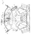
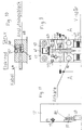
- a view is shown, partly as a sectional view, of a fiber welding device in particular intended for welding optical fiber ribbons.
- the view/section is taken substantially centrally through the device and the view is seen in parallel to and the sectional surfaces perpendicularly to the direction of the fibers which are to be welded to each other.
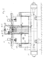
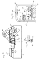
- Fig. 2 a view is shown, which also partly is a cross-sectional view, of the welding device, in which the view is taken in a direction perpendicular to the fibers as indicated at 1 and the sectional surfaces are parallel to the fibers, so that this picture is perpendicular to the picture of Fig. 1.
- the components of the device are carried by an elongated frame bar 3 having a rectangular cross section, which is supported on a base 5 by means of four oblique legs 7.
- the legs 7 can comprise elastic, cushioning intermediate pieces, such as 9.
- Centrally on the frame bar 3 is a centre frame 11 attached and stands up therefrom.
- the centre frame 11 has generally an isosceles triangular shape, as seen in a longitudinal direction parallel to the frame bar 3 and to inserted fibers, the triangle having its point between the two equal legs directed downwards towards the frame bar 3 and having an upper, substantially horizontal and flat surface and having two symmetrically located projections or triangular halves 15.
- the projections 15 carry light sources and cameras, see hereinafter.
- the horizontal top surface of the centre frame 11 carries an electrode housing 17, to which parts are attached, which are required for retaining the ends of the fibers and for the alignment thereof with each other, and further welding electrodes, as will be described hereinafter.
- an electrode housing 17 At the exterior sides of the projections 15 oblique cylindrical through-holes 19 are provided, which extend in parallel to the exterior cut-off sides of the projections and the axes of which are located in a vertical centre plane.
- This centre plane is simultaneously a symmetry plane of most of the components of the device and in this plane also the end surfaces of the fibers to be spliced to each other are located.
- the axes of the holes 19 and the exterior cut-off surfaces of the projections 15 are located in an angle of between 30 and 45° in relation to a vertical plane, in the preferred case in an angle between 35 and 40° and preferably about 37°.
- light passes from light sources arranged in the bottom end of the holes, such as from light emitting diodes 21.
- diaphragm plates 23 which are constituted by plates, which perpendicularly project into the interior of the holes 19 and are arranged in slots in the centre frame 11 at a distance from the top openings thereof, this distance being approximately equal to the diameter of the holes 19.
- the aperture plates 23 have a straight inner or lower edge and project into approximately the centre of the holes 19, so that the light is allow to pass through a window, having an approximately semi-circular shape.
- light diffusing means are arranged, such as suitable optical gratings 25, in order to produce a uniform illumination.
- Camera units 27, see also Fig. 3, are inserted with their front parts in corresponding holes in the oblique surfaces of the inverted triangular shape of the centre frame 11.
- the camera units 27 have a front part 29, which contains their optical systems.
- the optical axes of the optical systems are parallel to the axes of the holes 19 and cross the longitudinal axis of the fiber ribbons to be spliced, exactly in the splicing plane and are preferably also located in this plane.
- the prolongations of the holes for the camera units 27 continue up to the bottom sides of the electrode housing 17 in order for light from the splicing region of the fibers to be imaged by the optical systems on light sensitive elements of the camera units 27, the light sensitive elements being located at a plane 31 and arranged in an oblique angle and thus not perpendicularly to the axes of the optical system, this angle being adapted to produce a sharp picture of all individual fibers in fiber ribbons to be spliced.
- the upper part of the centre frame 11 and the electrode housing 17 are protected by two identical casing halves 33, which are capable of swinging towards and away from each other.
- casing halves 33 On the interior side of the casings, at the topmost portions thereof having approximately horizontal surfaces, mirrors 35 are arranged having horizontal reflecting surfaces. The mirrors 35 are placed, so that light rays from the light diffusing means or diffusor elements 25 can be mirrored therein and reflected by their reflecting surfaces, so that the reflected light rays can enter the optical systems of the camera units 27 and be conducted therein towards the light sensitive surfaces in the camera units.
- the fiber ribbons 1 to be spliced are retained, see Fig. 2, by fixtures or retainers 39, which are retained by locking elements 41 at the somewhat sloping top surfaces of parallelogram blocks 43, see Swedish patent application 9300578-3, filed March 22, 1993.
- the parallelogram blocks 43 are thus arranged having their longitudinal direction perpendicular to the triangular shape of the centre frame 11. They have rectangular recesses 45 comprising thin, uniformly thick, remaining vertical portions 47. Their bottom portions are attached to the top side of the frame bar 3 and their top portions comprise the sloping planes, at which the fixtures 39 are located.
- the top portions of the parallelogram blocks 43 can be moved from their rest positions having the vertical portions 47 in a straight configuration to positions closer to the transversal symmetry plane of the device by operating control motors 48 acting on levers 50 arranged in posts 49, which are attached to the frame bar 3 outside the parallelogram blocks 43. Then the straight vertical portions 47 are somewhat bent.
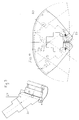
- the casing halves 33 which have identical shapes and are rotatable around shafts 51, which are located in the longitudinal direction of the device, i.e. generally also in the longitudinal direction of the fibers 1, see also Fig. 4.
- Recesses 52 intended for thumbs of an operator in order to make the opening and closing movement are arranged on the outside of the casings 33, close to the border surface, the recesses being visible in Fig. 1.
- the movements of the casing halves are coupled to each other by gear segments 53 engaging each other, so that the casings move in a coupled way towards or away from each other in order to seal, in their position engaging each other at the border surface, the space around the electrode housing 17 at least in directions upwards.
- a magnet 54 see Fig. 2, arranged on one of the casings for cooperation with a corresponding armature on the other casing.
- the casings 33 provide a shielding from exterior particles and protect the operator from the electric arc used in the welding operation. They have a design which saves space and their shafts are so arranged, that the casings in the movement are always located close to the interior parts of the welding device.
- the casings 33 have upper portions and side portions, the latter generally having the shape of circular sectors.
- the shafts 51 are arranged in regions at the sector points and at the interior sector edge and adjacent to the sector points also the gear segments 53 are located.
- microswitches are provided, not shown, which are arranged to cut-off the current from a possible electrical high voltage, which is supplied to the electrodes, in order to protect the operator.
- the exterior parts of the top portions of the casings 33 have generally the shape of parts of an envelope surface of a circular cylinder, the axis of the cylinder coinciding with the respective shaft 51.
- the inner parts of the upper portions at the border surface between the casing halves are essentially flat and are located in the same horizontal plane, when the casings are brought to each other.
- the mirrors 35 are arranged at the connection to the outer-most, part-cylindrical parts.
- Sealings 55 see Fig. 1, are arranged in protruding edges 56 of an exterior protecting housing, not shown, and are engaged with the part-cylindrical parts of the casings 33 and the side surfaces. They are arranged, so that they seal against the casings, in any positions thereof.
- the electrode housing 17, see Fig. 5, comprises a substantially rectangular block of high voltage resistant polymer material. Electrodes 57, between the points of which an electrical arc is formed in a splicing operation, are located in grooves having quadratic cross sections. The grooves are made in the top surface of the housing 17 and extend centrally in the longitudinal direction of the housing, perpendicularly to the fibers to be welded to each other. At the rear portions of the grooves transverse recesses 59 are provided, see also the view from above in Fig. 9, in which spring plates 61 are arranged. The spring plates, see Figs. 6 and 7, have a U-shape, comprising a cut-out 63 in the leg of the U-shape, which faces the points of the electrodes.
- the rear portion of the electrodes 57 pass in order to be pressed by the marginal portions of the plates adjacent to the cut-outs in a direction towards their front ends or towards their points by cooperation with abutment rings 63 rigidly attached at a small distance from the rear ends of the electrodes, see also Fig. 8.
- abutment rings 63 rigidly attached at a small distance from the rear ends of the electrodes, see also Fig. 8.
- These abutment rings also form stops for the movement of the electrodes 57 in this direction and thereby defines by engaging with the corresponding front side surfaces in the recesses 59, the position of the electrodes in their longitudinal directions.
- Electric high voltage is conducted to the electrode 57 from electrically conducting, elongated contact bodies 64 having a rectangular cross section, which are placed tightly in recesses in the electrode housing 17 below the grooves, in which the electrodes are located, see also the sectional view in Fig. 10, so that the contact bodies have contact with the bottom surface of the electrodes 57 along a generatrix thereof over a major portion of the length of the electrodes.
- the contact bodies 64 have a portion 68, projecting to the side and horizontally and having the shape of a rectangular block, at approximately their centre portions, which projecting portion is arranged tightly in a corresponding recess in the electrode housing 17 and has its top surface located in the same plane as the top surface of the electrode housing and its bottom surface in the same plane as the bottom surface of the oblong portions of the contact bodies.
- Screws 65 of a suitable metal pass in threaded bores down from the top side of the projecting portion 68 of the contact bodies 64.
- the screws 65 press with their lower ends against end portions, from which the electric isolation has been removed, of electrical high voltage cables 66, which thereby are pressed against the bottom surface in holes in the bottom portions of the contact bodies 54, through which the ends carrying no electric isolation enter.
- Corresponding holes are made from one side of the electrode housing 17, so that the cable ends can be entered therethrough into the holes of the contact bodies 64.
- retainer blocks 67, 67' are attached by means of screws, see Fig. 12, which secure the electrodes finally in the position in which their abutment rings 63 engage in the recesses 59.
- One retainer block 67' is higher than the other block 67 and carries at its top elevated portion a light source, not shown, which directs a light beam to the very welding location. This arrangement facilitates when inserting fibers and adjusting them in the respective V-grooves in the case where the surrounding illumination is bad.
- a ceramic V-groove plate 69 Centrally in the electrode housing 17, in a transverse recess in the top surface thereof, a ceramic V-groove plate 69 is provided, which has a central recess, which interrupts the V-grooves 70, see Fig. 9, and has a location corresponding to the region between the points of the electrodes 57, in which the electric arc is formed, when welding fibers to each other.
- the fibers are retained at their positions in the V-grooves 70 by means of a hold-down arm 71, which is mounted to be movable in the electrode house 17 about a shaft 73 parallel to the longitudinal direction of the device and the fiber direction.
- the hold-down arm 71 has at its front end two individually movable hold-down units 75, see also Figs.
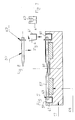
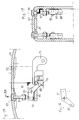
- the hold-down arm 71 is automatically folded down, when the casings 33 are brought to their closed positions. This is produced by means of a freely rotatable wheel 81, see Figs. 13, 2 and 1, which rotates about a shaft 83 attached to the side wall of the corresponding casing half 33.
- the wheel 81 has a groove at its periphery, in which a rubber ring 85 is mounted, and this ring comes in contact with the top side of the hold-down arm 71 and can bring it downwards, when the casing half is rotated inwards.
- the hold-down units 75 are, as has been mentioned above, elastically arranged. They have a U-shape, as seen perpendicular to inserted fibers, see Fig. 13, and the legs of the U-shape are located in recesses, see Fig. 9, on the sides of the front end of the hold-down arm 71 having a fork-shape, see also Fig. 13, in which each fork arm with its front end is bent downwards.
- Two helical compression springs 86 are located in holes extending upwards in the fork arms, see Fig.
- a pin 87 is attached in holes in the legs of the U-shape and pass through an oblong hole 88 in the hold-down arm, so that it and thereby the hold-down elements 75 can move vertically, as seen in the folded-down position of the hold-down arm 71.
- the pin 87 projects through some distance towards the free side of the hold-down arm 71.
- levers 91 are movably mounted at shafts 93, which are attached to the side portions of the protecting casing halves 33.
- Such a lever 91 has then the recess 89 at one of its ends, whereas the other rear end, which is located on the opposite side of the lever shaft 93, is influenced as its bottom side by a helical compression spring 96 acting between this end and a support block 95, so that the front end of the lever 91 is located in the lowest position possible.
- the support block 95 is attached to a vertical side portion of the protecting casing 33.
- a push rod 97 With the top side of the rear end of the lever 91 is the lower end of a push rod 97 engaged, which is movably mounted in the casing half 33, which is located above the lever.
- the upper end of the push rod 97 is enlarged in order to form an operating knob 99, which is located in a recess from the exterior side of the casing 33, so the knob 99 is accessible from the outside of the casing, see also Fig. 1.
- the rear end of the lever 91 moves downwards and its front ends upwards.
- the recess 89 at the front end then engages the projecting end of the pin 87 and thereby lifts the down hold unit 75.
- possible inserted optical fibers are released and it is possible to adjust their positions.
- the knob 99 is released, whereby the fibers are again retained.
Landscapes
- Physics & Mathematics (AREA)
- Engineering & Computer Science (AREA)
- Plasma & Fusion (AREA)
- General Physics & Mathematics (AREA)
- Optics & Photonics (AREA)
- Mechanical Coupling Of Light Guides (AREA)
- Treatment Of Fiber Materials (AREA)
- Arc Welding In General (AREA)
- Butt Welding And Welding Of Specific Article (AREA)
Applications Claiming Priority (2)
| Application Number | Priority Date | Filing Date | Title |
|---|---|---|---|
| SE9701954 | 1997-05-23 | ||
| SE9701954A SE511820C2 (sv) | 1997-05-23 | 1997-05-23 | Anordning för hopsvetsning av optiska fibrer |
Publications (3)
| Publication Number | Publication Date |
|---|---|
| EP0890852A2 true EP0890852A2 (fr) | 1999-01-13 |
| EP0890852A3 EP0890852A3 (fr) | 1999-06-02 |
| EP0890852B1 EP0890852B1 (fr) | 2006-03-01 |
Family
ID=20407077
Family Applications (1)
| Application Number | Title | Priority Date | Filing Date |
|---|---|---|---|
| EP98850082A Expired - Lifetime EP0890852B1 (fr) | 1997-05-23 | 1998-05-19 | Dispositif blindé de soudage pour fibres optiques |
Country Status (5)
| Country | Link |
|---|---|
| US (1) | US5961865A (fr) |
| EP (1) | EP0890852B1 (fr) |
| JP (1) | JPH1190625A (fr) |
| DE (1) | DE69833640T2 (fr) |
| SE (1) | SE511820C2 (fr) |
Cited By (2)
| Publication number | Priority date | Publication date | Assignee | Title |
|---|---|---|---|---|
| US6814124B2 (en) * | 1999-04-26 | 2004-11-09 | Telefonaktiebolaget Lm Ericsson (Publ) | Optical fiber splicing apparatus |
| WO2008132086A1 (fr) * | 2007-04-26 | 2008-11-06 | Ccs Technology, Inc. | Appareil d'épissurage de fibres optiques et procédé de fonctionnement d'un appareil d'épissurage de fibres optiques |
Families Citing this family (11)
| Publication number | Priority date | Publication date | Assignee | Title |
|---|---|---|---|---|
| JP3345856B2 (ja) * | 1999-09-09 | 2002-11-18 | 古河電気工業株式会社 | 光ファイバ融着接続機のスクリーニング機構 |
| SE523329C2 (sv) * | 2000-06-20 | 2004-04-13 | Ericsson Telefon Ab L M | Bestämning av optisk fibertyp |
| US6844520B2 (en) * | 2002-09-26 | 2005-01-18 | General Electric Company | Methods for fabricating gas turbine engine combustors |
| US6764230B1 (en) * | 2003-03-21 | 2004-07-20 | Future Instruments Fiber Optics Ab | Optical fiber splicing device |
| US7488125B2 (en) * | 2004-01-23 | 2009-02-10 | Fujikura Ltd. | Optical fiber fusion splicer and covering device for high voltage part thereof |
| RU2407618C2 (ru) * | 2008-11-06 | 2010-12-27 | Федеральное государственное унитарное предприятие "Государственный космический научно-производственный центр им. М.В. Хруничева" | Устройство для сборки под сварку кольцевых стыков емкостей |
| CH700691B1 (de) * | 2009-03-20 | 2020-09-15 | Diamond Sa | Vorrichtung und Verfahren zum Spleissen von Lichtwellenleitern, sowie Verwendung eines Endstückes in einer Vorrichtung zum Spleissen. |
| JP5290929B2 (ja) * | 2009-10-20 | 2013-09-18 | 古河電気工業株式会社 | 融着接続機 |
| WO2013146138A1 (fr) | 2012-03-29 | 2013-10-03 | 株式会社フジクラ | Dispositif d'épissage par fusion de fibres optiques |
| JP5209126B1 (ja) | 2012-03-29 | 2013-06-12 | 株式会社フジクラ | 光ファイバ融着接続機 |
| CN107807421B (zh) * | 2017-12-15 | 2019-10-11 | 中国电子科技集团公司第四十一研究所 | 一种光纤熔接放电电极高度自动调整装置及方法 |
Family Cites Families (12)
| Publication number | Priority date | Publication date | Assignee | Title |
|---|---|---|---|---|
| JPS55155314A (en) * | 1979-05-21 | 1980-12-03 | Nippon Telegr & Teleph Corp <Ntt> | Connecting method of optical fiber and its connector |
| GB2117916B (en) * | 1982-02-17 | 1986-08-28 | Standard Telephones Cables Ltd | Optic fibre fusion splicing |
| JPS5938718A (ja) * | 1982-08-30 | 1984-03-02 | Furukawa Electric Co Ltd:The | 光フアイバ融着接続用保持装置 |
| DE3245229A1 (de) * | 1982-12-07 | 1984-06-07 | Siemens AG, 1000 Berlin und 8000 München | Thermisches lichtwellenleiter-schweissgeraet |
| DE3789751T2 (de) * | 1986-10-27 | 1994-12-22 | The Furukawa Electric Co., Ltd., Tokio/Tokyo | Vorrichtung zum axialen Zentrieren beim Verschmelzen optischer Fasern. |
| US5046813A (en) * | 1988-09-07 | 1991-09-10 | Fujikura Ltd. | Method and apparatus for aligning a plurality of single-fiber cables, and method of simultaneously fusion-splicing such cables |
| FR2671409B1 (fr) * | 1991-01-08 | 1994-06-10 | Alcatel Fibres Optiques | Microsoudeuse pour fibres optiques et procede de soudage a l'aide de cette microsoudeuse. |
| JPH04315107A (ja) * | 1991-04-12 | 1992-11-06 | Sumitomo Electric Ind Ltd | 光ファイバの接続方法 |
| US5328893A (en) * | 1991-06-24 | 1994-07-12 | Superconductor Technologies, Inc. | Superconducting devices having a variable conductivity device for introducing energy loss |
| JP3256918B2 (ja) * | 1994-01-28 | 2002-02-18 | 古河電気工業株式会社 | 光学部品の溶接固定装置 |
| US5524163A (en) * | 1994-12-29 | 1996-06-04 | Sumitomo Electric Industries, Ltd. | Apparatus for splicing optical fibers and method for the same |
| AU4937696A (en) * | 1995-03-07 | 1996-09-23 | Siemens Aktiengesellschaft | Splicing device for welding optical fibres |
-
1997
- 1997-05-23 SE SE9701954A patent/SE511820C2/sv not_active IP Right Cessation
-
1998
- 1998-05-19 EP EP98850082A patent/EP0890852B1/fr not_active Expired - Lifetime
- 1998-05-19 DE DE69833640T patent/DE69833640T2/de not_active Expired - Lifetime
- 1998-05-22 US US09/083,185 patent/US5961865A/en not_active Expired - Lifetime
- 1998-05-25 JP JP10181318A patent/JPH1190625A/ja active Pending
Cited By (3)
| Publication number | Priority date | Publication date | Assignee | Title |
|---|---|---|---|---|
| US6814124B2 (en) * | 1999-04-26 | 2004-11-09 | Telefonaktiebolaget Lm Ericsson (Publ) | Optical fiber splicing apparatus |
| WO2008132086A1 (fr) * | 2007-04-26 | 2008-11-06 | Ccs Technology, Inc. | Appareil d'épissurage de fibres optiques et procédé de fonctionnement d'un appareil d'épissurage de fibres optiques |
| US7874742B2 (en) | 2007-04-26 | 2011-01-25 | Corning Cable Systems Llc | Splicing device for optical fibers and method for operating a splicing device for optical fibers |
Also Published As
| Publication number | Publication date |
|---|---|
| EP0890852B1 (fr) | 2006-03-01 |
| SE511820C2 (sv) | 1999-11-29 |
| EP0890852A3 (fr) | 1999-06-02 |
| DE69833640D1 (de) | 2006-04-27 |
| JPH1190625A (ja) | 1999-04-06 |
| SE9701954D0 (sv) | 1997-05-23 |
| SE9701954L (sv) | 1998-11-24 |
| US5961865A (en) | 1999-10-05 |
| DE69833640T2 (de) | 2007-02-01 |
Similar Documents
| Publication | Publication Date | Title |
|---|---|---|
| US5961865A (en) | Shielded welding device for optical fibers | |
| CN104516059A (zh) | 多光纤连接器检查 | |
| KR100354943B1 (ko) | 광학적표면검사장치 | |
| KR960011399B1 (ko) | 광학 소자 조립 장치 | |
| US6788406B2 (en) | Device and methods of inspecting soldered connections | |
| GB1571580A (en) | Lighting means for illuminating the graticule scale lines on the interior of a cathode ray tube | |
| US4926249A (en) | Color image reader having a lens and prism incorporated into a single unit | |
| CN100474099C (zh) | 光学装置的制造方法 | |
| EP0245089B1 (fr) | Microscope | |
| EP3820137B1 (fr) | Appareil d'imagerie | |
| US5483065A (en) | Electron beam microanalyzer | |
| JP2019514051A (ja) | 垂直方向のカメラを含む時空間光変調結像システム、および物体を共焦点結像させるための方法 | |
| JP3631303B2 (ja) | 大型標本観察用顕微鏡装置 | |
| US4983997A (en) | Microphotographic apparatus with automatic film format reflection | |
| KR20160007680A (ko) | 카메라 모듈의 렌즈 위치 결정 장치 | |
| CN109960026B (zh) | 照明装置、显微镜装置以及盒 | |
| JP6815412B2 (ja) | 時空間光変調結像システム、物体を共焦点結像させる方法、およびキャリア・ホイール装置 | |
| CN223006034U (zh) | 用于检测样品中成分和/或含量的装置 | |
| KR100663196B1 (ko) | 일체형 프로브 마운트 및 이를 포함하는 현미경 | |
| JPH10246857A (ja) | 斜光照明装置 | |
| JP2006125980A (ja) | 魚眼レンズ検査装置 | |
| EP0392719A2 (fr) | Dispositifs de couplage optiques | |
| CN120063669A (zh) | 一种光学镜头测试仪器及光学镜头测试方法 | |
| US7277190B2 (en) | Measurement system with an optical measurement arrangement | |
| US6778713B1 (en) | Image reading apparatus |
Legal Events
| Date | Code | Title | Description |
|---|---|---|---|
| PUAI | Public reference made under article 153(3) epc to a published international application that has entered the european phase |
Free format text: ORIGINAL CODE: 0009012 |
|
| AK | Designated contracting states |
Kind code of ref document: A2 Designated state(s): DE FR GB IT |
|
| AX | Request for extension of the european patent |
Free format text: AL;LT;LV;MK;RO;SI |
|
| RHK1 | Main classification (correction) |
Ipc: G02B 6/255 |
|
| PUAL | Search report despatched |
Free format text: ORIGINAL CODE: 0009013 |
|
| AK | Designated contracting states |
Kind code of ref document: A3 Designated state(s): AT BE CH CY DE DK ES FI FR GB GR IE IT LI LU MC NL PT SE |
|
| AX | Request for extension of the european patent |
Free format text: AL;LT;LV;MK;RO;SI |
|
| 17P | Request for examination filed |
Effective date: 19991125 |
|
| AKX | Designation fees paid |
Free format text: DE FR GB IT |
|
| RAP1 | Party data changed (applicant data changed or rights of an application transferred) |
Owner name: TELEFONAKTIEBOLAGET LM ERICSSON (PUBL) |
|
| 17Q | First examination report despatched |
Effective date: 20040908 |
|
| GRAP | Despatch of communication of intention to grant a patent |
Free format text: ORIGINAL CODE: EPIDOSNIGR1 |
|
| GRAS | Grant fee paid |
Free format text: ORIGINAL CODE: EPIDOSNIGR3 |
|
| GRAA | (expected) grant |
Free format text: ORIGINAL CODE: 0009210 |
|
| AK | Designated contracting states |
Kind code of ref document: B1 Designated state(s): DE FR GB IT |
|
| PG25 | Lapsed in a contracting state [announced via postgrant information from national office to epo] |
Ref country code: IT Free format text: LAPSE BECAUSE OF FAILURE TO SUBMIT A TRANSLATION OF THE DESCRIPTION OR TO PAY THE FEE WITHIN THE PRESCRIBED TIME-LIMIT;WARNING: LAPSES OF ITALIAN PATENTS WITH EFFECTIVE DATE BEFORE 2007 MAY HAVE OCCURRED AT ANY TIME BEFORE 2007. THE CORRECT EFFECTIVE DATE MAY BE DIFFERENT FROM THE ONE RECORDED. Effective date: 20060301 |
|
| REG | Reference to a national code |
Ref country code: GB Ref legal event code: FG4D |
|
| REF | Corresponds to: |
Ref document number: 69833640 Country of ref document: DE Date of ref document: 20060427 Kind code of ref document: P |
|
| ET | Fr: translation filed | ||
| PLBE | No opposition filed within time limit |
Free format text: ORIGINAL CODE: 0009261 |
|
| STAA | Information on the status of an ep patent application or granted ep patent |
Free format text: STATUS: NO OPPOSITION FILED WITHIN TIME LIMIT |
|
| 26N | No opposition filed |
Effective date: 20061204 |
|
| PGFP | Annual fee paid to national office [announced via postgrant information from national office to epo] |
Ref country code: GB Payment date: 20130528 Year of fee payment: 16 Ref country code: DE Payment date: 20130530 Year of fee payment: 16 |
|
| PGFP | Annual fee paid to national office [announced via postgrant information from national office to epo] |
Ref country code: FR Payment date: 20130606 Year of fee payment: 16 |
|
| REG | Reference to a national code |
Ref country code: DE Ref legal event code: R119 Ref document number: 69833640 Country of ref document: DE |
|
| GBPC | Gb: european patent ceased through non-payment of renewal fee |
Effective date: 20140519 |
|
| REG | Reference to a national code |
Ref country code: DE Ref legal event code: R119 Ref document number: 69833640 Country of ref document: DE Effective date: 20141202 |
|
| REG | Reference to a national code |
Ref country code: FR Ref legal event code: ST Effective date: 20150130 |
|
| PG25 | Lapsed in a contracting state [announced via postgrant information from national office to epo] |
Ref country code: DE Free format text: LAPSE BECAUSE OF NON-PAYMENT OF DUE FEES Effective date: 20141202 |
|
| PG25 | Lapsed in a contracting state [announced via postgrant information from national office to epo] |
Ref country code: GB Free format text: LAPSE BECAUSE OF NON-PAYMENT OF DUE FEES Effective date: 20140519 Ref country code: FR Free format text: LAPSE BECAUSE OF NON-PAYMENT OF DUE FEES Effective date: 20140602 |