EP0890933A2 - Capteurs piézo-électriques - Google Patents
Capteurs piézo-électriques Download PDFInfo
- Publication number
- EP0890933A2 EP0890933A2 EP98202437A EP98202437A EP0890933A2 EP 0890933 A2 EP0890933 A2 EP 0890933A2 EP 98202437 A EP98202437 A EP 98202437A EP 98202437 A EP98202437 A EP 98202437A EP 0890933 A2 EP0890933 A2 EP 0890933A2
- Authority
- EP
- European Patent Office
- Prior art keywords
- piezoelectric
- lane
- roadway
- polarity
- sensor
- Prior art date
- Legal status (The legal status is an assumption and is not a legal conclusion. Google has not performed a legal analysis and makes no representation as to the accuracy of the status listed.)
- Withdrawn
Links
- 230000001939 inductive effect Effects 0.000 claims description 5
- 239000000463 material Substances 0.000 description 29
- 238000000034 method Methods 0.000 description 15
- 238000004519 manufacturing process Methods 0.000 description 13
- 230000005684 electric field Effects 0.000 description 11
- 230000010287 polarization Effects 0.000 description 10
- 238000001125 extrusion Methods 0.000 description 7
- 230000007935 neutral effect Effects 0.000 description 6
- 229920000642 polymer Polymers 0.000 description 4
- 238000010586 diagram Methods 0.000 description 3
- 238000011156 evaluation Methods 0.000 description 2
- 238000009434 installation Methods 0.000 description 2
- 238000005204 segregation Methods 0.000 description 2
- 230000007704 transition Effects 0.000 description 2
- BQCIDUSAKPWEOX-UHFFFAOYSA-N 1,1-Difluoroethene Chemical compound FC(F)=C BQCIDUSAKPWEOX-UHFFFAOYSA-N 0.000 description 1
- 239000002033 PVDF binder Substances 0.000 description 1
- 238000004873 anchoring Methods 0.000 description 1
- 239000003990 capacitor Substances 0.000 description 1
- 239000004020 conductor Substances 0.000 description 1
- 238000013461 design Methods 0.000 description 1
- 230000009977 dual effect Effects 0.000 description 1
- 230000000694 effects Effects 0.000 description 1
- 230000006870 function Effects 0.000 description 1
- 238000010030 laminating Methods 0.000 description 1
- 239000011159 matrix material Substances 0.000 description 1
- 238000005259 measurement Methods 0.000 description 1
- 238000012986 modification Methods 0.000 description 1
- 230000004048 modification Effects 0.000 description 1
- 229920002981 polyvinylidene fluoride Polymers 0.000 description 1
- 238000012545 processing Methods 0.000 description 1
- 230000003595 spectral effect Effects 0.000 description 1
- XLYOFNOQVPJJNP-UHFFFAOYSA-N water Substances O XLYOFNOQVPJJNP-UHFFFAOYSA-N 0.000 description 1
Images



Classifications
-
- G—PHYSICS
- G08—SIGNALLING
- G08G—TRAFFIC CONTROL SYSTEMS
- G08G1/00—Traffic control systems for road vehicles
- G08G1/01—Detecting movement of traffic to be counted or controlled
- G08G1/02—Detecting movement of traffic to be counted or controlled using treadles built into the road
-
- G—PHYSICS
- G08—SIGNALLING
- G08G—TRAFFIC CONTROL SYSTEMS
- G08G1/00—Traffic control systems for road vehicles
- G08G1/065—Traffic control systems for road vehicles by counting the vehicles in a section of the road or in a parking area, i.e. comparing incoming count with outgoing count
Definitions
- the present invention relates to piezoelectric sensors and to traffic sensing arrangements having piezoelectric sensing elements for identifying a lane in which a vehicle is detected.
- the invention also relates to a method of manufacturing a piezoelectric sensor.
- Traffic engineers typically collect data concerning traffic speed and density, vehicle size, loading and type, and vehicle condition as an aid in determining the design parameters of roads, highways, bridges and other structures.
- acquiring the data required for complete evaluation and planning of these structures becomes difficult because of the need to monitor many lanes simultaneously.
- the volume and complexity of the data required to make a complete evaluation of multi-lane roadways renders manual traffic counting impractical.
- automatic traffic recorders have been developed for recording data in a form which may be readily tabulated and evaluated.
- traffic information is obtained by placing an elongate traffic sensor strip, having a plurality of detector segments appropriately spaced along the sensor strip, across a multi-lane roadway to monitor traffic in the lanes of the multi-lane roadway.
- the detector segments may each include a pair of parallel spaced conducting plates which generate an output signal when pushed together by the weight of a vehicle, or the detector segments may each comprise a coaxial cable in place of the parallel spaced conducting plates.
- a separate detector segment is placed in each lane so that the lane can be identified; however, in another embodiment, two or more coaxial cables are placed across the roadway to provide lane segregation.
- the first coaxial cable extends completely across two lanes of traffic while the second coaxial cable extends only across one lane.
- the lane through which a vehicle passes is that identified by logically ANDing the positive outputs from each cable which are generated when the coaxial cables are deflected by the wheels of a vehicle. In this manner, the lane is identified in accordance with whether a positive pulse is received from just one or both cables.
- the traffic sensor arrangements of US-A-3,911,390 typically have a low profile so as not to be readily visible to motorists and a gradually tapering profile to provide a smooth tire transition for a vehicle, and are generally designed to be quite durable so as to resist wear and damage from dirt or moisture.
- durability is improved by anchoring the sensors in the roadway so that they will remain in position over a long period of time.
- the sensors are difficult to install in the roadway, require the roadway to be closed for installation and do not alleviate certain safety concerns.
- US-A-5,008,666 traffic measurement equipment including a pair of coaxial cables having piezoelectric materials and a vehicle presence detector embedded therein for detecting vehicle count, vehicle length, vehicle time of arrival, vehicle speed, the number of axles per vehicle, axle distance per vehicle, vehicle gap, headway and axle weights, and the like. This is accomplished by extending the coaxial cables including the piezoelectric materials across the roadway, measuring signals induced in the cables by passage of vehicle wheels thereover, and processing the signals to compute a total integrated spectral power of the measured signals so as to establish an empirical relationship between speed and weight of the vehicle wheels passing over the coaxial cables.
- a separate detector is installed in each lane and thus no means are provided for collecting traffic data from multiple lanes using a minimum number of easy to install detectors.
- the present invention provides a piezoelectric sensor which can generate pulses of different polarities or states in different longitudinal sections thereof so that, for example, if the piezoelectric material is extended across a multi-lane roadway, pulses of different polarities are generated in different lanes so as to uniquely identify those lanes, such material being easy to install so that it can be placed across a multi-lane roadway with minimum disruption of traffic.
- the present invention consists according to one aspect thereof in an elongate piezoelectric sensor as defined in claim 1.
- a sensor may be used in a traffic sensing arrangement to discriminate between lanes of a roadway by generating electrical signals having different polarities in different lanes of the roadway.
- the polarity of the poling field of the piezoelectric material is varied in different longitudinal sections of the piezoelectric material so that the piezoelectric material will generate pulses having different polarities in different longitudinal sections.
- the piezoelectric sensor When stretched across a roadway, the piezoelectric sensor will give, for example, a positive output when run over by a vehicle in one lane and a negative output when run over by a vehicle in another lane. Then, by using only two bipolar piezoelectric sensors in a single traffic sensor, traffic data from up to eight lanes of traffic can be discriminated between using only one simple to install traffic sensor.
- the piezoelectric sensor may have a first polarity for a finite length in a first longitudinal section thereof and a second polarity, different from the first polarity, for a finite length in a second longitudinal section which is adjacent the first longitudinal section in a longitudinal direction of the sensor.
- the piezoelectric sensor may be configured as a piezoelectric cable or a piezoelectric film produced by a variety of techniques.
- the piezoelectric sensor may be formed from a first piezoelectric cable or film having the first polarity which is spliced to a second piezoelectric cable or film having the second polarity.
- the spliced piezoelectric cables also may be enclosed in a braided sheath and an outer jacket for protection from dirt and moisture and the like.
- the piezoelectric material also may comprise a piezoelectric cable or film which is polarized during manufacture to have the first polarity in the first longitudinal section and then is polarized to have the second polarity in the second longitudinal section.
- the piezoelectric material may be polarized into-more than two polarities as desired.
- the piezoelectric sensor may be formed by twisting the piezoelectric material such that it has different polarization states on either side of the twist in said material. The same effect may also be achieved by placing conducting electrodes on either side of the longitudinal sections of the piezoelectric material and connecting electrodes on opposite sides of the piezoelectric material in different longitudinal sections by way of through holes so that electric fields of different polarities can be applied to adjacent longitudinal sections.
- a traffic sensing arrangement can incorporate such a piezoelectric sensor for sensing the number of vehicles travelling in each lane of a predetermined portion of a roadway.
- a traffic sensing arrangement comprises a piezoelectric sensor stretched across a width of the predetermined porion of the roadway so as to generate an electrical signal when deflected by a vehicle.
- the generated electrical signal has a first polarity when deflected by a vehicle in a first lane of the roadway and a second polarity when deflected by a vehicle in a second lane of the roadway.
- the polarity of the generated electrical signals may be detected by a roadside electronic device for determining from the polarity of the received electrical signal(s) in which lane of the roadway the piezoelectric sensor has been deflected by a vehicle.
- the electronic device may comprise, for example, first and second counters corresponding to first and second lanes of the roadway, the first counter being incremented when the electrical signal has the first polarity and the second counter being incremented when the electrical signal has the second polarity.
- the electronic device may also include a -microprocessor which may also be responsive to an inductive loop which detects the passage of a vehicle so as to determine how many electrical signals generated in a particular lane correspond to a single vehicle.
- a traffic sensing arrangement in accordance with another aspect of the invention measures the number of vehicles travelling in each lane L of a predetermined portion of a multi-lane roadway by stretching n piezoelectric sensors across a width of the predetermined portion of the roadway and generating at each of the n piezoelectric sensors an electrical signal having one of s states when that piezoelectric sensor is deflected by a vehicle in one of the lanes L of the roadway.
- At least L s n lanes of the multi-lane roadway may be uniquely identified in this manner.
- the n piezoelectric sensors are disposed concentrically with respect to each other in the same cable housing and placed over at least two lanes of the predetermined portion of the roadway.
- one concentric piezoelectric sensor may be placed across two lanes while the other differently polarized concentric piezoelectric sensor is placed across only one lane.
- a separate piezoelectric sensor for each lane of the predetermined portion of the roadway may be disposed in a rugged housing which is stretched across the predetermined portion of the roadway.
- a separate cable within the housing is connected to each of the piezoelectric sensors in each lane for relaying the electrical signals generated by the piezoelectric sensors to a measuring location where the lane from which the traffic data is measured is readily determined by the cable from which the traffic data is received.
- traffic sensors having piezoelectric sensors are used for discriminating between traffic data received from different lanes of a roadway.
- Elongate piezoelectric sensors having different polarities in respective longitudinal sections thereof are provided and are stretched across respective lanes of the roadway so that piezoelectric sensor portions in different lanes of the roadway generate electrical signals of different polarities when a vehicle passes thereover.
- the respective lanes may be discriminated between by using simple Boolean logic.
- a positive pulse is generatedby a section of the piezoelectric sensor in lane 1, while a negative pulse is generated by a section of the piezoelectric sensor in lane 2.
- the lanes are then discriminated between on the basis of the polarity of the pulses received from said sensor sections.
- this technique may be expanded so that at least L - s n lanes can be monitored using n sensors having s states.
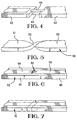
- FIG. 1 to 3 illustrate embodiments of piezoelectric sensors formed from piezoelectric cables
- Figures 4 to 7 illustrate embodiments of piezoelectric sensors formed from piezoelectric films.
- a bipolar piezoelectric sensor may be formed by splicing a positively polarized piezoelectric cable 10 by means of splices 12 to a negatively polarized piezoelectric cable 14.
- the inner core conductors 16, the electrodes 17 and the dielectric layers 18 of the cables are spliced as indicated diagrammatically so that the lengths of cable on either side of splices 12 generate electrical signals of different polarities upon deflection.
- Figure 2 shows an embodiment of a piezoelectric sensor similar to that of Figure 1 excepting that the spliced positively polarized piezoelectric cable 10 and the negatively polarized piezoelectric cable 14 are wrapped in a braided sheath 19 and an outer jacket 20 for protection from the elements.
- the piezoelectric cables are thus protected from dirt and moisture, thereby extending the useful life of the cables.
- FIG. 3 shows an embodiment of a multi-polar piezoelectric sensor comprising a piezoelectric cable 30 which has a positively polarized (+) longitudinal section 31 and a negatively polarized (-) longitudinal section 32 separated by a neutral region (0) 33.
- a piezoelectric sensor is provided by forming a cable of piezoelectric material such as PVDF and PVF 2 using extrusion or some other known manufacturing process, and polarizing the piezoelectric cable during manufacture by applying a positive electric field to the piezoelectric cable during extrusion for a period of time sufficient to obtain a positively polarized length of cable of the desired length.
- each positively and negatively polarized section approximates to the width of a lane of roadway, with the neutral region corresponding to the portion of the roadway between lanes.
- Figure 4 shows an embodiment of a piezoelectric sensor comprising separate piezoelectric films 40 and 42 which are spliced by means 44 so that the respective films have opposite polarities.
- Figure 5 shows another embodiment of a piezoelectric sensor comprising a single piezoelectric film 50 which is twisted at 53 so that the sections 51 and 52 of the piezoelectric film on opposite sides of the twisted part of the film have opposite polarities along a longitudinal axis of the piezoelectric film 50.
- Figure 6 shows another embodiment of a piezoelectric sensor, comprising a single piezoelectric film 60 having through holes 62 by way of which separate electrodes 64 along both sides, only one of which is shown, of adjacent longitudinal sections 65 and 66, respectively of the piezoelectric film 60 are electrically connected in such a manner that the polarities of electric fields applied to the electrodes are reversed, as shown, for adjacent longitudinal regions of the piezoelectric film 60.
- Figure 7 shows an embodiment of a multi-polar piezoelectric sensor comprising a single piezoelectric film 70 produced in accordance with the technique described above with reference to Figure 3, excepting that the piezoelectric cable 30 is replaced by the piezoelectric film 70 in the extrusion process.
- a piezoelectric material when used in a traffic sensor arrangement, the normal convention is for the piezoelectric material to provide a positive output pulse when run over by a vehicle. Similarly, if the polarity of the polarizing field were reversed during the manufacturing process, the piezoelectric material would provide a negative output pulse when run over by a vehicle. Accordingly, if a piezoelectric sensor of the type described above is manufactured so as to have reversed polarity in different sections thereof, one sensor may be used for two lanes of traffic as shown in Figure 8. In particular, a piezoelectric sensor 80 is so produced that it has different polarities or states in respective longitudinal sections thereof which have lengths approximating the width of a lane of a roadway.
- the piezoelectric sensor 80 is placed across a two lane roadway 82 such that a deflection of the piezoelectric sensor 80 in one lane causes the generation of a negative pulse, while deflection of the piezoelectric sensor 80 in the other lane causes the generation of a positive pulse.
- An electronic device 84 then senses the polarity of the received pulse to determine which lane detected passage of a vehicle.
- one sensor may be used to readily discriminate between data from two lanes of traffic.
- Figure 9 shows an embodiment in which two bipolar piezoelectric sensors A and B are employed in parallel with each other to monitor up to eight lanes of traffic.
- piezoelectric sensor A and piezoelectric sensor B have polarities along their respective longitudinal sections corresponding to each lane of a road 82' so that a unique combination of electrical signals will be received by an electronic device 84' for discriminating the traffic data from each of the lanes 1 through 8.
- lane 3 is identified when a negative pulse is received from piezoelectric sensors A and B
- lane 6 is identified when a positive pulse is received from sensor A and a negative pulse is received from sensor B.
- a lane is identified by the combination of piezoelectric sensor outputs as just described.
- the piezoelectric sensors A and B are mounted very close to each other so that the time difference between an event occurring on piezoelectric sensor A and piezoelectric sensor B will be much less than the time that will elapse until another pulse from the same piezoelectric sensor is received.
- the piezoelectric sensors A and B may be separate piezoelectric sensors which are placed in parallel with each other across the roadway. However, for ease of installation of the piezoelectric sensors A and B, they may be disposed in a single homogeneous unit in a number of different configurations. Preferably, the homogeneous unit is quite rugged so as to withstand the wear and tear from vehicle traffic and is also insulated from dirt and water. If the piezoelectric sensors A and B are formed from piezoelectric film, the homogeneous unit may be formed by stacking or wrapping and then laminating different layers of the film together so that the sensors are parallel to each other in a very intimate manner.
- the piezoelectric cable is preferably manufactured so that the piezoelectric sensors are concentric, by forming the first piezoelectric cable and then extruding or wrapping a second layer of piezoelectric material having a different polarity on top of the first cable. Polarization would then occur between the outer electrode of the inner cable and a second outer electrode.
- such a concentric piezoelectric sensor preferably includes a center core 100, about which an inner piezoelectric polymer layer 102 (sensor A) is wrapped.
- An inner electrode 104 is then formed on the inner piezoelectric polymer layer 102, and a dielectric layer 106 is disposed about the inner electrode 104.
- a middle electrode 108 is then placed about the dielectric 106, and an outer piezoelectric polymer layer 110 (sensor B) disposed about the middle electrode 108.
- An outer electrode 112 is then formed about the outer piezoelectric polymer 110, and the entire structure is disposed within an outer jacket 114 for protection from the elements.
- the number of layers and piezoelectric sensors in the multi-layer piezoelectric cable of Figure 10 can be increased. However, the number of layers in the resulting multi-layer piezoelectric cable is limited by the number of channels of information that are actually needed.
- the number of lanes of a roadway that can be monitored with a given number of sensors is limited by the number of "states" that are available for the piezoelectric sensors.
- states means the polarization states of the piezoelectric sensor which may be positive (+), negative (-), or neutral (0).
- more lanes may be monitored by appropriately offsetting the piezoelectric sensors.
- piezoelectric sensors are described above which have different polarization states in different lanes when used in a traffic sensor.
- one technique for manufacturing such piezoelectric sensors is to splice lengths of positive and negative polarized material together. Although this can achieve the needed result of having a cable or film with dual polarities, it introduces the weakness of the splices of the coaxial material. Accordingly, in accordance with another manufacturing technique, only the inner core of the piezoelectric material is spliced and is then enclosed in a continuous braided sheath and outer jacket as shown in Figure 2 in order to protect the piezoelectric material from the elements. This produces a more robust package although labor is involved in splicing the positively and negatively polarized material.
- the preferred technique for manufacturing the piezoelectric sensors is to switch the polarity of the polarization voltage during the manufacturing process to conform the longitudinal sections of the piezoelectric material to the desired polarization: For example 2.4m (eight feet) of material may be manufactured with a positive polarization voltage, the next 1.2m (four feet) of the material not being polarized, and the next 2.4m (eight feet) of the material being negatively polarized.
- the switching could be accomplished in any format desired to give the correct matrix of possibilities.
- the measured results may be confused if positive and negative pulses are generated by different sections of the same sensor at the same time. It will, however, also be appreciated that many different techniques may be used to solve this problem including, for example, doubling the intensity of the polarization in one direction. Also to reduce the likelihood of such confusion, the durations of the pulses caused by the deflection of the piezoelectric sensors can be minimized. Typical pulse durations are on the order of 4 msec, which gives a greater than 99% accuracy.
- Figure 11 shows another embodiment of a traffic sensing arrangement in which separate piezoelectric sensor elements P 110-116 are disposed in each lane.
- the lanes are identified by connecting piezoelectric sensor elements P 110 to 116 to respective cables C 118 to 122, as shown, so that a separate cable is provided for each lane and as an input to an electronic device 84''.
- Separate switch boxes 124 to 128 are preferably provided between the respective piezoelectric sensors for appropriately connecting the piezoelectric sensor elements P 110 to 116 to respective cables C 118 to 122.
- Jumpers 130 may be used to connect the cables through the switch boxes 124 to 128 to the electronic device 84'' shown.
- each of the respective cables C 118 to 122 are balanced by connecting capacitors 132 to 136 across each of the switch boxes 124 to 128 as shown.
- the piezoelectric sensor elements P 110 to 116 may be offset from each other so that each is included in its own respective cable C 118 to 122 for providing an input to the electronic device 84''.
- Figure 12 shows the embodiment of Figure 11 in its housing 138, which is preferably of a durable material and is tapered at its edges so as to facilitate passage of a vehicle.
- the section including the switch boxes is marked by a stripe 140 so that the piezoelectric sensor elements can be properly aligned on the roadway.
- the signals generated by the respective piezoelectric sensors elements are fed via the cables C 118 to 122 into a junction box 142 which is typically at the side of the roadway.
- the junction box 142 may be connected via a cable 144 or a modem or the like, to a remote electronic device 84''.
- a similar housing may be provided for each of the other embodiments described above.
- Figure 13 shows an exemplary embodiment of an electronic device 84''.
- the electronic device includes a plurality of operational amplifiers 146 to 152 each for detecting the polarity of the received electrical signals from a respective input cable.
- the polarities of the received signals are typically determined by comparing each received electrical signal to a trigger level in accordance with known techniques.
- the resulting signals are then fed into a microprocessor 154 for determining which lane is addressed by the particular combination of positive and negative electrical signals. This may be accomplished by using simple Boolean logic elements or a simple truth table or the like.
- the traffic sensing arrangement preferably further includes an inductive loop 156 of the type described, for example, in US-A-5,008,666.
- the inductive loop 156 detects the passage of a vehicle in order to determine the number of electrical signals which were received during passage of the vehicle; thereby to determine the number of axles corresponding to a particular vehicle, to aid in vehicle classification.
- the microprocessor 154 increments the appropriate lane counter 158 to 164 to indicate that a vehicle has passed through the lane identified by the received electrical signals. Otherwise, the received electrical signals may be time stamped by the microprocessor 154 and the vehicle type determined so that lane data, vehicle type data, and time and date data can be stored in a memory 166.
- the electronics device 84'' is powered by a battery 168 and the collected data is retrieved on a regular basis based on the memory size of the memory 166 and/or the charge duration of battery 168. At the end of some predetermined time, for example, a week or a month, traffic data from the memory 166 is dumped and battery 168 is recharged or replaced.
- vehicle speed data may be calculated by placing two piezoelectric sensors at a known distance from each other and then calculating the time delay between deflections using know techniques.
- differently polarized piezoelectric sensors may be placed across the roadway to provide lane segregation in a manner similar to that described in US-A-3,911,390.
- a first piezoelectric sensor with a first polarity could extend completely across two lanes of traffic while a second piezoelectric sensor with a second polarity could extend only across one lane. The lane through which a vehicle passes would then be detected from the polarities of the received signals rather than the logical ANDing of the positive outputs from each cable as described in US-A-3,911,390.
Landscapes
- Physics & Mathematics (AREA)
- General Physics & Mathematics (AREA)
- Traffic Control Systems (AREA)
- Road Signs Or Road Markings (AREA)
Applications Claiming Priority (3)
| Application Number | Priority Date | Filing Date | Title |
|---|---|---|---|
| US07/992,577 US5486820A (en) | 1992-12-18 | 1992-12-18 | Traffic sensor having piezoelectric sensors which distinguish lanes |
| US992577 | 1992-12-18 | ||
| EP93308850A EP0602792B1 (fr) | 1992-12-18 | 1993-11-05 | Capteurs piézoélectriques |
Related Parent Applications (1)
| Application Number | Title | Priority Date | Filing Date |
|---|---|---|---|
| EP93308850A Division EP0602792B1 (fr) | 1992-12-18 | 1993-11-05 | Capteurs piézoélectriques |
Publications (2)
| Publication Number | Publication Date |
|---|---|
| EP0890933A2 true EP0890933A2 (fr) | 1999-01-13 |
| EP0890933A3 EP0890933A3 (fr) | 2000-05-31 |
Family
ID=25538483
Family Applications (2)
| Application Number | Title | Priority Date | Filing Date |
|---|---|---|---|
| EP93308850A Expired - Lifetime EP0602792B1 (fr) | 1992-12-18 | 1993-11-05 | Capteurs piézoélectriques |
| EP98202437A Withdrawn EP0890933A3 (fr) | 1992-12-18 | 1993-11-05 | Capteurs piézo-électriques |
Family Applications Before (1)
| Application Number | Title | Priority Date | Filing Date |
|---|---|---|---|
| EP93308850A Expired - Lifetime EP0602792B1 (fr) | 1992-12-18 | 1993-11-05 | Capteurs piézoélectriques |
Country Status (5)
| Country | Link |
|---|---|
| US (1) | US5486820A (fr) |
| EP (2) | EP0602792B1 (fr) |
| JP (1) | JPH06265418A (fr) |
| CA (1) | CA2109132A1 (fr) |
| DE (1) | DE69323602T2 (fr) |
Cited By (1)
| Publication number | Priority date | Publication date | Assignee | Title |
|---|---|---|---|---|
| CN107145828A (zh) * | 2017-04-01 | 2017-09-08 | 纵目科技(上海)股份有限公司 | 车辆全景图像处理方法及装置 |
Families Citing this family (15)
| Publication number | Priority date | Publication date | Assignee | Title |
|---|---|---|---|---|
| US5752215A (en) * | 1995-02-28 | 1998-05-12 | Livingstone Legend Enterprises (Propiretary) Ltd. | Apparatus and method for classifying vehicles using electromagnetic waves and pattern recognition |
| JPH10132669A (ja) * | 1996-10-30 | 1998-05-22 | Whitaker Corp:The | ピエゾケーブル及びそれを用いたワイヤハーネス |
| US5835027A (en) * | 1996-11-07 | 1998-11-10 | Tyburski; Robert M. | Residual charge effect traffic sensor |
| US5850192A (en) * | 1996-12-27 | 1998-12-15 | Minnesota Mining And Manufacturing Company | Apparatus for sensing vehicles |
| US6204756B1 (en) * | 1998-10-23 | 2001-03-20 | Visteon Global Technologies, Inc. | Diagnostics for vehicle deformation sensor system |
| DE19962310C2 (de) * | 1999-12-23 | 2003-06-18 | Bosch Gmbh Robert | Spurmessvorrichtung |
| US6417785B1 (en) * | 2000-09-01 | 2002-07-09 | Traffic Monitoring Services, Inc. | Permanent in-pavement roadway traffic sensor system |
| US20030206118A1 (en) * | 2002-05-02 | 2003-11-06 | Jeffrey E. Verkleeren | Force transmitting sensor housing |
| US6870489B2 (en) | 2003-02-28 | 2005-03-22 | 3M Innovative Properties Company | Vehicle sensing system |
| US20050127677A1 (en) * | 2003-12-03 | 2005-06-16 | Luttrull Jeffrey K. | Roadway generating electrical power by incorporating piezoelectric materials |
| CN102466489A (zh) * | 2010-11-15 | 2012-05-23 | 中国科学院微电子研究所 | 多压电传感器点阵系统及多压电传感器阵列系统 |
| CN103557968B (zh) * | 2013-11-22 | 2015-06-17 | 哈尔滨理工大学 | 压电传感器中压电陶瓷片焊接点的定位装置及方法 |
| JP2019067969A (ja) * | 2017-10-03 | 2019-04-25 | 三井化学株式会社 | ケーブル構造体、力センサー、及びアクチュエータ |
| CN112710370A (zh) * | 2020-11-12 | 2021-04-27 | 西安航天三沃机电设备有限责任公司 | 应用于治超非现场执法系统的多车道称重判别方法及装置 |
| CN118447682A (zh) * | 2024-04-29 | 2024-08-06 | 长安大学 | 一种具有自供能和信息无线传输功能的埋入式道路交通感知装置 |
Family Cites Families (23)
| Publication number | Priority date | Publication date | Assignee | Title |
|---|---|---|---|---|
| FR534532A (fr) * | 1921-02-23 | 1922-03-28 | Carburateur spécial pour moteur lent | |
| US3631387A (en) * | 1969-04-01 | 1971-12-28 | Gulf & Western Industries | Unit extension circuit means for traffic control system |
| FR2145099A5 (fr) * | 1971-07-08 | 1973-02-16 | Inst Francais Du Petrole | |
| US3753223A (en) * | 1971-08-16 | 1973-08-14 | Minnesota Mining & Mfg | System to determine the directional mode of travel of vehicles on a roadway |
| US3750127A (en) * | 1971-10-28 | 1973-07-31 | Gen Dynamics Corp | Method and means for sensing strain with a piezoelectric strain sensing element |
| US3911390A (en) * | 1973-11-07 | 1975-10-07 | Richard H Myers | Traffic sensor strip |
| US4194194A (en) * | 1978-01-30 | 1980-03-18 | The United States Of America As Represented By The Secretary Of The Navy | Piezoelectric vibration detector for sensing a nearby intruder |
| DE2902545C2 (de) * | 1979-01-24 | 1985-04-04 | Akzo Gmbh, 5600 Wuppertal | Faden mit Leitschichten |
| FR2487555A1 (fr) * | 1980-07-28 | 1982-01-29 | Automatisme Cie Gle | Detecteur de passage d'objets pesants sur une chaussee |
| US4609845A (en) * | 1984-07-06 | 1986-09-02 | Raychem Corporation | Stretched piezoelectric polymer coaxial cable |
| DE8424175U1 (de) * | 1984-08-16 | 1984-11-08 | Pfaff Industriemaschinen Gmbh, 6750 Kaiserslautern | Vorschubantrieb fuer den naehguthalter einer zick-zack-stichgruppennaehmaschine |
| FR2577315A1 (fr) * | 1984-11-16 | 1986-08-14 | Thomson Csf | Capteur lineaire de pression. |
| US4712423A (en) * | 1985-01-04 | 1987-12-15 | Laboratoire Central Des Ponts Et Chaussees | Process and apparatus for measuring the dynamic loads applied to a highway by the road traffic |
| GB8620474D0 (en) * | 1986-08-22 | 1986-10-01 | Bicc Plc | Electrical switch |
| US4943805A (en) * | 1986-11-13 | 1990-07-24 | Dennison James L | Conduit-enclosed induction loop for a vehicle detector |
| EP0287250B1 (fr) * | 1987-04-02 | 1996-08-14 | Franz Josef Gebert | Equipement de mesure de trafic |
| FR2625808B1 (fr) * | 1988-01-12 | 1990-09-21 | Electronique Controle Mesure S | Dispositif de detection de passage de vehicules ou pietons sur une chaussee a film piezo-electrique ou resistif |
| US4888581A (en) * | 1988-04-06 | 1989-12-19 | Aritech Corporation | Pressure sensitive security system for tracking motion over a surface |
| DE69006235T2 (de) * | 1989-03-10 | 1994-05-05 | Franz Josef Gebert | Kabeleinbau zur Überwachung des Strassenverkehrs. |
| FR2662006A1 (fr) * | 1990-05-11 | 1991-11-15 | Thermocoax Cie | Dispositif de detection de donnees relatives au passage de vehicules sur une chaussee. |
| US5265481A (en) * | 1990-12-19 | 1993-11-30 | Kistler Instrumente Ag | Force sensor systems especially for determining dynamically the axle load, speed, wheelbase and gross weight of vehicles |
| US5239148A (en) * | 1991-05-15 | 1993-08-24 | Progressive Engineering Technologies Corp. | Lane discriminating traffic counting device |
| FR2681698A1 (fr) * | 1991-09-25 | 1993-03-26 | Thermocoax Cie | Detecteur d'essieux pour installation en surface de chaussee a plusieurs voies. |
-
1992
- 1992-12-18 US US07/992,577 patent/US5486820A/en not_active Expired - Fee Related
-
1993
- 1993-10-25 CA CA002109132A patent/CA2109132A1/fr not_active Abandoned
- 1993-11-05 EP EP93308850A patent/EP0602792B1/fr not_active Expired - Lifetime
- 1993-11-05 EP EP98202437A patent/EP0890933A3/fr not_active Withdrawn
- 1993-11-05 DE DE69323602T patent/DE69323602T2/de not_active Expired - Fee Related
- 1993-12-17 JP JP5344203A patent/JPH06265418A/ja active Pending
Cited By (2)
| Publication number | Priority date | Publication date | Assignee | Title |
|---|---|---|---|---|
| CN107145828A (zh) * | 2017-04-01 | 2017-09-08 | 纵目科技(上海)股份有限公司 | 车辆全景图像处理方法及装置 |
| CN107145828B (zh) * | 2017-04-01 | 2020-06-16 | 纵目科技(上海)股份有限公司 | 车辆全景图像处理方法及装置 |
Also Published As
| Publication number | Publication date |
|---|---|
| US5486820A (en) | 1996-01-23 |
| DE69323602D1 (de) | 1999-04-01 |
| JPH06265418A (ja) | 1994-09-22 |
| EP0602792B1 (fr) | 1999-02-24 |
| DE69323602T2 (de) | 1999-08-12 |
| EP0602792A1 (fr) | 1994-06-22 |
| EP0890933A3 (fr) | 2000-05-31 |
| CA2109132A1 (fr) | 1994-06-19 |
Similar Documents
| Publication | Publication Date | Title |
|---|---|---|
| EP0602792B1 (fr) | Capteurs piézoélectriques | |
| US5554907A (en) | Vehicle speed measurement apparatus | |
| US7042369B2 (en) | Road traffic monitoring system | |
| US6917308B2 (en) | Surface-mount traffic sensors | |
| US3911390A (en) | Traffic sensor strip | |
| US6744378B1 (en) | Roadway sensor with improved insulated signal carrying wires | |
| Rajab et al. | Vehicle classification and accurate speed calculation using multi-element piezoelectric sensor | |
| EP0564054B1 (fr) | Installation de câbles pour la détection du trafic | |
| US6417785B1 (en) | Permanent in-pavement roadway traffic sensor system | |
| EP0639290A1 (fr) | Systeme de capteurs routiers | |
| US5360953A (en) | Lane discriminating traffic counting device | |
| JPH09512118A (ja) | 磁力計車両検出器 | |
| US6469266B2 (en) | Road vehicle axle sensor | |
| US3836899A (en) | Intrusion detection and locating system | |
| JPH06111178A (ja) | 車両検出器 | |
| Woods et al. | Speed measurement with inductance loop speed traps | |
| JPH1090018A (ja) | 地盤等の歪み観測システム | |
| KR100198259B1 (ko) | 교통량 무인 검출시스템 | |
| CN210691600U (zh) | 地感式交通量检测装置 | |
| JP2541531B2 (ja) | 駐車検出方法 | |
| JP2001084477A (ja) | 交通監視システム | |
| JPS59142404A (ja) | 車輌のトレツド測定方式 | |
| KR940008196B1 (ko) | 교통감지장치 | |
| JP2005173955A (ja) | 車輌検出システム | |
| JPS59136603A (ja) | 車両のトレツド測定装置 |
Legal Events
| Date | Code | Title | Description |
|---|---|---|---|
| PUAI | Public reference made under article 153(3) epc to a published international application that has entered the european phase |
Free format text: ORIGINAL CODE: 0009012 |
|
| AC | Divisional application: reference to earlier application |
Ref document number: 602792 Country of ref document: EP |
|
| AK | Designated contracting states |
Kind code of ref document: A2 Designated state(s): DE FR GB |
|
| PUAL | Search report despatched |
Free format text: ORIGINAL CODE: 0009013 |
|
| AK | Designated contracting states |
Kind code of ref document: A3 Designated state(s): DE FR GB |
|
| 17P | Request for examination filed |
Effective date: 20001124 |
|
| 17Q | First examination report despatched |
Effective date: 20010420 |
|
| STAA | Information on the status of an ep patent application or granted ep patent |
Free format text: STATUS: THE APPLICATION IS DEEMED TO BE WITHDRAWN |
|
| 18D | Application deemed to be withdrawn |
Effective date: 20011031 |