EP0891029A2 - Procédé de contrÔle d'une ligne - Google Patents
Procédé de contrÔle d'une ligne Download PDFInfo
- Publication number
- EP0891029A2 EP0891029A2 EP98810583A EP98810583A EP0891029A2 EP 0891029 A2 EP0891029 A2 EP 0891029A2 EP 98810583 A EP98810583 A EP 98810583A EP 98810583 A EP98810583 A EP 98810583A EP 0891029 A2 EP0891029 A2 EP 0891029A2
- Authority
- EP
- European Patent Office
- Prior art keywords
- line
- transmission network
- phase
- compensator
- network
- Prior art date
- Legal status (The legal status is an assumption and is not a legal conclusion. Google has not performed a legal analysis and makes no representation as to the accuracy of the status listed.)
- Withdrawn
Links
Images
Classifications
-
- H—ELECTRICITY
- H02—GENERATION; CONVERSION OR DISTRIBUTION OF ELECTRIC POWER
- H02J—ELECTRIC POWER NETWORKS; CIRCUIT ARRANGEMENTS OR SYSTEMS FOR SUPPLYING OR DISTRIBUTING ELECTRIC POWER; SYSTEMS FOR STORING ELECTRIC ENERGY
- H02J3/00—Circuit arrangements for AC mains or AC distribution networks
- H02J3/26—Arrangements for eliminating or reducing asymmetry in polyphase networks
-
- Y—GENERAL TAGGING OF NEW TECHNOLOGICAL DEVELOPMENTS; GENERAL TAGGING OF CROSS-SECTIONAL TECHNOLOGIES SPANNING OVER SEVERAL SECTIONS OF THE IPC; TECHNICAL SUBJECTS COVERED BY FORMER USPC CROSS-REFERENCE ART COLLECTIONS [XRACs] AND DIGESTS
- Y02—TECHNOLOGIES OR APPLICATIONS FOR MITIGATION OR ADAPTATION AGAINST CLIMATE CHANGE
- Y02E—REDUCTION OF GREENHOUSE GAS [GHG] EMISSIONS, RELATED TO ENERGY GENERATION, TRANSMISSION OR DISTRIBUTION
- Y02E40/00—Technologies for an efficient electrical power generation, transmission or distribution
- Y02E40/50—Arrangements for eliminating or reducing asymmetry in polyphase networks
Definitions
- the invention relates to a method for operating a multi-phase line integrated in a transmission network for the transmission of electrical energy and a Device for performing this method.
- the invention as defined in claim 1 is based on the task of a procedure for the Operation of a multi-phase, in a line network integrated line indicating the availability this line significantly improved in the event of a fault, furthermore intended to be a device for performing this method can be specified.
- the method according to the invention allows using the availability is comparatively low to significantly improve disturbed lines.
- the invention enables better utilization of existing lines, what particularly in areas where the construction of new high-voltage transmission lines is not enforceable significant improvement in transmission security existing lines.
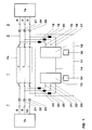
- Fig. 1 shows a section of a three-phase Transmission network 1, which consists of two subnetworks 1a and 1b, is shown schematically.
- this transmission network 1 connects a three-phase line 2 a first, with the Subnetwork la connected network node 3, the terminals 4,5,6 has, with a second, connected to the subnet 1b Network node 7, which has the terminals 8,9,10.
- Terminals 4 and 8 extend phase R of line 2
- terminals 5 and 9 phase S extends Line 2 and between terminals 6 and 10 extends phase T of line 2.
- Line 2 has one switchable area 2a, at the two ends in each phase in a known arrangement not designated Circuit breakers are provided, which the respective Switch off phase and completely from the transmission network 1 can disconnect if, for example, an error in this Phase should occur.
- the phase R is as shown switched off, the other two phases S and T are still in operation.
- a balancing compensator 11 is parallel to the line 2 switched.
- the balancing compensator 11 has two with GTO thyristors or three-point inverters connected with IGBTs 12 and 13 on by means of a separate Compensating conductor 14 are interconnected.
- the first Three-point inverter 12 has three input terminals 15, 16, 17.
- the input terminal 15 is connected to the terminal 4 of the Network node 3 electrically connected, in this Connection a control throttle 18 is provided.
- the Input terminal 16 is connected to terminal 5 of network node 3 electrically connected, in this connection a control throttle 19 is provided.
- the input terminal 17 is electrically conductive with the terminal 6 of the network node 3 connected, in which connection a control throttle 20th is provided.
- the second three-point inverter 13 has three Input terminals 21, 22, 23.
- the input terminal 21 is with the terminal 8 of the network node 7 is connected in an electrically conductive manner, a control throttle 24 is provided in this connection is.
- the input terminal 22 is connected to the terminal 9 of the Network node 7 electrically connected, in this Connection a control throttle 25 is provided.
- the Input terminal 23 is connected to terminal 10 of network node 7 electrically connected, in this connection a control throttle 26 is provided.
- Each of the phases R, S and T is in front of the switchable area 2a of the line 2 with schematically indicated sensors 27,28,29, which the monitoring of the state and serve the load on line 2, in particular among other things also through the phases R, S and T of Line 2 flowing currents detected.
- These sensors 27,28,29 stand on the one hand with the protection of line 2 and on the other hand with a processing unit 30 in Active connection, which is also the result of the sensors 27,28,29 processed data processed. If the protection one Detects errors and, if necessary, control commands for the Shutdown of individual phases of line 2 generated, see above the processing unit 30 recognizes this fact also and ensures the appropriate control of the Three-point inverter 12, which is then activated that it starts as part of the balancing compensator 11 work. If this three-point inverter 12 before this Activation as reactive power compensator or as Voltage regulator has worked, he takes on this task continues to be true if that is in view of the changed Operating state of the transmission network 1 should be necessary.
- Each of the phases R, S and T can be switched off Area 2a of line 2 with schematically shown Sensors 31,32,33 equipped, which the monitoring of the Condition and the load on line 2 serve, in particular, among other things, the phases R, S and T of line 2 flowing currents detected.
- This Sensors 31, 32, 33 stand on the one hand with the protection of the Line 2 and on the other hand with a processing unit 34 in operative connection, which is also the result of the sensors 31,32,33 processed data processed.
- the processing unit 34 recognizes this fact also and ensures the appropriate control of the Three-point inverter 13, which is then activated that it also starts as part of the Symmetry compensator 11 to work. If this Three-point inverter 13 before this activation as Reactive power compensator or voltage regulator worked he will continue to perform this task, if that is in the With regard to the changed operating state of the Transmission network 1 should be necessary.
- the two Processing units 30 and 34 can by means of a Control line to be connected, creating a synchronous operation of the two three-point inverters 12 and 13 is reached.
- the two processing units 30 and 34 work with the protection and with the superordinate Control technology for the transmission network 1 together, so that Operational reliability of the transmission network 1 essential is increased.
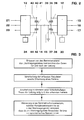
- the Fig.2 shows a way like that DC voltage outputs of the three-point inverters 12 and 13 can be connected.
- the three-point inverter 12 has a positive terminal 35, one on the output side Middle terminal 36 and a negative terminal 37. Between the positive terminal 35 and the middle terminal 36 is a Capacitor 38 arranged. Between the negative terminal 37 and the middle terminal 36 is a capacitor 39 is arranged. The two capacitors 38 and 39 have the same Capacity on. When the balancing compensator 11 is activated is, these two capacitors 38 and 39 serve as Energy storage.
- the three-point inverter 13 has one on the output side positive terminal 40, a middle terminal 41 and a negative Terminal 42 open. Between the positive terminal 40 and the A capacitor 43 is arranged in the middle terminal 41. Between the negative terminal 42 and the middle terminal 41 is on Capacitor 44 arranged. The two capacitors 43 and 44 have the same capacity. If the Balancing compensator 11 is activated, these two serve Capacitors 43 and 44 as energy stores. Usually the capacitors 38, 39, 43 and 44 have the same Capacity on. The two middle clamps 36 and 37 are connected to each other by the compensating conductor 14.
- the compensating conductor 14 is in the vicinity of the middle terminal 36 grounded, as shown by an earth connection 45. This grounding is likely to be straightforward, but it's under certain network conditions also possible, an ohmic Resistance in the earth connection 45 to switch.
- the Compensating conductor 14 and line 2 flow when the Balancing compensator 11 is activated, the currents of the Zero system.
- the zero system if the three-phase power system is regarded as a co-system, counter-system and zero system, completely suppressed.
- the balancing compensator 11 is activated in the Usually at the same time as the faulty ones are switched off Phase R of line 2. The transmission of electrical Energy then comes from those that are not faulty Phases of line 2, in this embodiment it is the phases S and T, which after switching off the error for the energy transfer is still available.
- the Balancing compensator 11 usually works before it Activation as reactive power compensator or as Voltage regulator, it also maintains this function, if it is additionally activated as a balancing compensator 11 is, if that with regard to the changed Operating state of the transmission network 1 is still necessary should be.
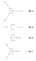
- FIGS. 4 to 7 are now considered to explain the mode of operation of the balancing compensator 11.
- FIG. 4 shows a vector diagram of the three currents of equal magnitude, which flow through the initially fault-free line 2 in normal operation assumed to be ideal.
- the dashed vector I R represents the current flowing in phase R
- the vector I S represents the current flowing in phase S
- the vector I T represents the current flowing in phase T.
- the three vectors I R , I S and I T are each rotated relative to one another by an angle a, this angle a being 120 ° in the ideal case.
- phase R is switched off due to an error, current I R can no longer flow through this phase of line 2; vector I R , shown in broken lines, must then be regarded as not present.
- the transmission network 1 is now asymmetrically loaded at this point. If this operating state were to be maintained, disturbances would occur on the rotating machines in a conventionally designed and operated transmission network 1 and comparatively large and impermissible voltage drops would occur. In this case, the protection of the transmission network 1 would have to switch off the faulty line 2 with three poles, and the associated disadvantages would have to be accepted in order to avoid major secondary damage. The faulty line would therefore fail completely for energy transmission.
- the current corresponding to the vector I R shown in FIG. 4 is sucked out of the transmission network 1 after the activation of the balancing compensator 11 by the three-point inverter 12, so that the sub-network la continues to use the same three-phase current as before the fault the vector diagram shown in FIG. 4.
- the three-point inverter 12 converts this single-phase current into a three-phase compensator current.
- This three-phase compensator current is composed, as can be seen from FIG. 5, of the following components: the vector I KR , which is directed in exactly the opposite direction to the current drawn out of the phase R of the sub-network 1 and represented by the vector I R and which is a third of the amount of the vector I R , the vector I KS , which is directed in exactly the opposite direction to the current flowing in the phase S of the transmission network 1 and represented by the vector I S and which has a third of the amount of the vector I S , and the vector I KT , which is exactly opposite to the current flowing in the phase T of the transmission network 1 and represented by the vector I T and which has a third of the amount of the vector I T.
- FIG. 6 shows the definitive vector diagram of the compensator current derived from FIG. 5 after the vectors I R and I KR have been superimposed on the resulting vector I KRD .
- This compensator current is superimposed on the currents flowing in the sub-network la, which are represented by the vectors I S and I T in FIG.
- the result of this superimposition is shown in FIG. 7.
- the resulting vectors I R1 , I S1 and I T1 represent the resulting symmetrical currents flowing in the phases R, S and T of the subnetwork la, they each have an amount of two thirds of the assigned in-phase vectors I R , I S and I T on.
- the vector I R1 corresponds to the vector I KRD of the compensator current in terms of magnitude and phase position.
- the subnetwork la like the subnetwork 1b, is to be regarded as a rigid network with a constant mains voltage which acts on the network node 3 and which immediately compensates for any current and voltage fluctuations in this area.
- the second three-point inverter 13 acts in a similar way to the three-point inverter 12 just described on the sub-network 1b of the transmission network 1, but it pulls a corresponding three-phase current out of the sub-network 1b and transforms it and feeds it in phase R to a single-phase a current corresponding to the vector I R in magnitude and phase into the subnet 1b.
- the currents belonging to the zero-sequence system flow through the compensating conductor 14 connecting the two three-point inverters 12 and 13.
- the circuit for the zero system closes via the two healthy phases S and T of line 2.
- the amount of the two vectors I S and I T which represent the currents flowing in the healthy phases, is always somewhat larger than the amount of the corresponding vectors I S and I T in undisturbed network operation when real network conditions are used.
- the two healthy phases S and T of line 2 therefore generally transmit much more than two thirds of the total power that line 2 which is not faulty can transmit.
- a line with one phase switched off depending on the length of the line, transmits in the range from 80% to 90% of the power transmitted in undisturbed operation. This advantageously high power, which can be transmitted with a single-phase faulty line 2, results in significantly improved operating behavior and better availability of the transmission network 1.
- balancing compensator 11 It is a variety of beneficial ones Possible applications of the balancing compensator 11 conceivable since its application is not only to the High voltage networks is limited, even in medium and The balancing compensator 11 can be used advantageously.
- the compensation head 14 can be retrofitted existing free line with a balancing compensator 11 usually in addition to the existing ones Overhead lines are attached. Because on the Compensating conductor 14 grounded on one side is not too high Can build tension is the space required for this additional conductors comparatively small, so on all sufficient space for overhead line masts common today is available. Even if the compensating conductor 14 because of high current loads are carried as a double line the available space is also sufficient for this. Of the subsequent installation of the compensating conductor 14 is accordingly possible with comparatively little effort.
Landscapes
- Engineering & Computer Science (AREA)
- Power Engineering (AREA)
- Supply And Distribution Of Alternating Current (AREA)
- Cable Transmission Systems, Equalization Of Radio And Reduction Of Echo (AREA)
Applications Claiming Priority (2)
| Application Number | Priority Date | Filing Date | Title |
|---|---|---|---|
| DE19729658A DE19729658A1 (de) | 1997-07-11 | 1997-07-11 | Verfahren zum Betrieb einer Leitung |
| DE19729658 | 1997-07-11 |
Publications (2)
| Publication Number | Publication Date |
|---|---|
| EP0891029A2 true EP0891029A2 (fr) | 1999-01-13 |
| EP0891029A3 EP0891029A3 (fr) | 2000-02-02 |
Family
ID=7835340
Family Applications (1)
| Application Number | Title | Priority Date | Filing Date |
|---|---|---|---|
| EP98810583A Withdrawn EP0891029A3 (fr) | 1997-07-11 | 1998-06-25 | Procédé de contrôle d'une ligne |
Country Status (3)
| Country | Link |
|---|---|
| US (1) | US6069779A (fr) |
| EP (1) | EP0891029A3 (fr) |
| DE (1) | DE19729658A1 (fr) |
Cited By (2)
| Publication number | Priority date | Publication date | Assignee | Title |
|---|---|---|---|---|
| EP2348597A1 (fr) * | 2010-01-20 | 2011-07-27 | SMA Solar Technology AG | Adaptation de prestations partielles s'écoulant par le biais de chaque phase d'un courant alternatif multiphase |
| DE102012110110A1 (de) * | 2012-10-23 | 2014-04-24 | Sma Solar Technology Ag | Wechselrichter, Verfahren zum Betreiben eines Wechselrichters und Energieversorgungsanlage mit einem Wechselrichter |
Families Citing this family (4)
| Publication number | Priority date | Publication date | Assignee | Title |
|---|---|---|---|---|
| US6956728B2 (en) * | 2003-02-28 | 2005-10-18 | Eaton Corporation | Method and apparatus to control modular asynchronous contactors |
| US20150295508A1 (en) * | 2013-06-17 | 2015-10-15 | Ronald David Conry | Power Management, Phase Balancing, and Energy Storage Method |
| US10148122B2 (en) | 2014-12-17 | 2018-12-04 | Abb Schweiz Ag | Systems and methods for implementing series compensators in static UPS |
| US11682904B2 (en) * | 2021-09-24 | 2023-06-20 | Cisco Technology, Inc. | Three-phase AC load unbalance detection and balancing method and circuit |
Family Cites Families (4)
| Publication number | Priority date | Publication date | Assignee | Title |
|---|---|---|---|---|
| DE2713073C3 (de) * | 1977-03-24 | 1979-09-27 | Siemens Ag, 1000 Berlin Und 8000 Muenchen | Symmetrierungseinrichtung für ein Drehstromnetz |
| DE3339428C2 (de) * | 1983-10-29 | 1987-04-16 | ANT Nachrichtentechnik GmbH, 7150 Backnang | Verfahren für ein Signalvergleichsschutz-System zur Überwachung von Übertragungsstrecken des elektrischen Energie-Versorgungsnetzes |
| US5134356A (en) * | 1990-06-22 | 1992-07-28 | Board Of Regents Of The University Of Washington | Reactive power compensator |
| US5710492A (en) * | 1994-12-22 | 1998-01-20 | Hitachi, Ltd. | Apparatus for monitoring and stabilizing power swing in a power system by utilizing a power electronics technique |
-
1997
- 1997-07-11 DE DE19729658A patent/DE19729658A1/de not_active Withdrawn
-
1998
- 1998-06-25 EP EP98810583A patent/EP0891029A3/fr not_active Withdrawn
- 1998-07-07 US US09/110,842 patent/US6069779A/en not_active Expired - Fee Related
Cited By (8)
| Publication number | Priority date | Publication date | Assignee | Title |
|---|---|---|---|---|
| EP2348597A1 (fr) * | 2010-01-20 | 2011-07-27 | SMA Solar Technology AG | Adaptation de prestations partielles s'écoulant par le biais de chaque phase d'un courant alternatif multiphase |
| WO2011089181A1 (fr) * | 2010-01-20 | 2011-07-28 | Sma Solar Technology Ag | Nivellement de puissances partielles circulant via les phases individuelles d'un réseau ca multiphase |
| CN102714414A (zh) * | 2010-01-20 | 2012-10-03 | 艾思玛太阳能技术股份公司 | 调节经由多相ac电网的各个相流动的局部功率 |
| CN102714414B (zh) * | 2010-01-20 | 2015-09-23 | 艾思玛太阳能技术股份公司 | 调节经由多相ac电网的各个相流动的局部功率 |
| US9270117B2 (en) | 2010-01-20 | 2016-02-23 | Sma Solar Technology Ag | Levelling partial powers flowing via the individual phases of a multi-phase AC grid |
| DE102012110110A1 (de) * | 2012-10-23 | 2014-04-24 | Sma Solar Technology Ag | Wechselrichter, Verfahren zum Betreiben eines Wechselrichters und Energieversorgungsanlage mit einem Wechselrichter |
| DE102012110110B4 (de) * | 2012-10-23 | 2016-12-08 | Sma Solar Technology Ag | Wechselrichter, Verfahren zum Betreiben eines Wechselrichters und Energieversorgungsanlage mit einem Wechselrichter |
| EP2912741B1 (fr) * | 2012-10-23 | 2018-09-12 | SMA Solar Technology AG | Onduleur, procédé faire fonctionner un onduleur et installation d'alimentation en énergie comprenant un onduleur |
Also Published As
| Publication number | Publication date |
|---|---|
| DE19729658A1 (de) | 1999-01-14 |
| EP0891029A3 (fr) | 2000-02-02 |
| US6069779A (en) | 2000-05-30 |
Similar Documents
| Publication | Publication Date | Title |
|---|---|---|
| EP1922803B1 (fr) | Dispositif de transmission d'energie electrique | |
| EP0166954B1 (fr) | Procédé pour la réduction des surtensions dynamiques dans un réseau de courant alternatif | |
| EP1040555B1 (fr) | Ensemble circuit convertisseur de courant presentant un circuit intermediaire a tension continue | |
| EP1296441B1 (fr) | Système de production d'énergie | |
| DE112018005677T5 (de) | Verfahren und vorrichtung zur fehlererkennung und zum schutz von elektrischen netzwerken | |
| EP3639353B1 (fr) | Impédance pour controler des courants de défaut dans un convertisseur c.c.h.t. | |
| EP0714565B1 (fr) | Systeme de detection de fuite a la terre de stator dans des machines triphasees | |
| EP4244967A1 (fr) | Précharge à isolation galvanique et contrôle d'isolement d'un convertisseur de puissance pour le couplage d'un réseau électrique ca mis à la terre à un réseau électrique cc non mis à la terre | |
| EP1855366A2 (fr) | Circuit et procédé pour la compensation du courant de défaut pendant un défaut de terre | |
| DE2509045A1 (de) | Verfahren beim betrieb einer gleichstromuebertragungsanlage und gleichstromuebertragungsanlage zur durchfuehrung des verfahrens | |
| EP3635851B1 (fr) | Unité de convertisseur de courant | |
| DE10247039B4 (de) | Querstromausgleichssteuerung für eine Stromanlage | |
| EP0187312B1 (fr) | Circuit de filtrage | |
| EP0891029A2 (fr) | Procédé de contrÔle d'une ligne | |
| DE69110138T2 (de) | Verfahren zur Diagnose der Verschlechterung der Isolierung eines elektrischen Gerätes. | |
| DE102017220109A1 (de) | Stromrichter | |
| DE69211815T2 (de) | Leistungswandlungssystem | |
| DE102020119104B3 (de) | Gleichrichteranordnung | |
| DE19736903A1 (de) | Umrichter mit Gleichspannungszwischenkreis sowie Verfahren zum Betrieb eines solchen Umrichters | |
| EP3830921B1 (fr) | Mise à la terre du point neutre avec limitation des surtensions pour un transformateur polyphasé | |
| WO2022101423A1 (fr) | Dispositif et procédé de mise à la terre d'un réseau à courant continu | |
| DE4026799A1 (de) | Verfahren zur selektiven erfassung von fehlern der leiter in hoch- und hoechstspannungsnetzen | |
| DE69508056T2 (de) | Stromrichterkupplung mit einer spannungsausgleichsschaltung | |
| DE102007024976A1 (de) | Vorrichtung zur Hochspannungsgleichstromübertragung | |
| EP1110797B1 (fr) | Installation et procédé pour protéger des convertisseurs de puissance contre une surcharge |
Legal Events
| Date | Code | Title | Description |
|---|---|---|---|
| PUAI | Public reference made under article 153(3) epc to a published international application that has entered the european phase |
Free format text: ORIGINAL CODE: 0009012 |
|
| AK | Designated contracting states |
Kind code of ref document: A2 Designated state(s): CH DE FR GB LI |
|
| AX | Request for extension of the european patent |
Free format text: AL;LT;LV;MK;RO;SI |
|
| PUAL | Search report despatched |
Free format text: ORIGINAL CODE: 0009013 |
|
| AK | Designated contracting states |
Kind code of ref document: A3 Designated state(s): AT BE CH CY DE DK ES FI FR GB GR IE IT LI LU MC NL PT SE |
|
| AX | Request for extension of the european patent |
Free format text: AL;LT;LV;MK;RO;SI |
|
| RAP1 | Party data changed (applicant data changed or rights of an application transferred) |
Owner name: ABB HOCHSPANNUNGSTECHNIK AG |
|
| 17P | Request for examination filed |
Effective date: 20000602 |
|
| AKX | Designation fees paid |
Free format text: CH DE FR GB LI |
|
| RAP1 | Party data changed (applicant data changed or rights of an application transferred) |
Owner name: ABB SCHWEIZ AG |
|
| STAA | Information on the status of an ep patent application or granted ep patent |
Free format text: STATUS: THE APPLICATION HAS BEEN WITHDRAWN |
|
| 18W | Application withdrawn |
Withdrawal date: 20020402 |