EP0891258B1 - Systeme d'impression a jet d'encre - Google Patents
Systeme d'impression a jet d'encre Download PDFInfo
- Publication number
- EP0891258B1 EP0891258B1 EP97905233A EP97905233A EP0891258B1 EP 0891258 B1 EP0891258 B1 EP 0891258B1 EP 97905233 A EP97905233 A EP 97905233A EP 97905233 A EP97905233 A EP 97905233A EP 0891258 B1 EP0891258 B1 EP 0891258B1
- Authority
- EP
- European Patent Office
- Prior art keywords
- ink
- tank
- level
- generator
- supply
- Prior art date
- Legal status (The legal status is an assumption and is not a legal conclusion. Google has not performed a legal analysis and makes no representation as to the accuracy of the status listed.)
- Expired - Lifetime
Links
- 238000007641 inkjet printing Methods 0.000 title claims abstract description 8
- 238000005259 measurement Methods 0.000 claims abstract description 18
- 230000008859 change Effects 0.000 claims abstract description 9
- 239000002904 solvent Substances 0.000 claims description 28
- 238000007639 printing Methods 0.000 claims description 25
- 238000012546 transfer Methods 0.000 claims description 16
- 238000012544 monitoring process Methods 0.000 claims description 5
- 230000004044 response Effects 0.000 claims description 3
- 239000007788 liquid Substances 0.000 abstract description 21
- 238000004140 cleaning Methods 0.000 description 6
- 230000000630 rising effect Effects 0.000 description 5
- 238000012986 modification Methods 0.000 description 3
- 230000004048 modification Effects 0.000 description 3
- 238000011161 development Methods 0.000 description 2
- 230000000694 effects Effects 0.000 description 2
- 238000001704 evaporation Methods 0.000 description 2
- 230000008020 evaporation Effects 0.000 description 2
- 238000011010 flushing procedure Methods 0.000 description 2
- 238000000034 method Methods 0.000 description 2
- 238000002156 mixing Methods 0.000 description 2
- 238000002360 preparation method Methods 0.000 description 2
- 230000009471 action Effects 0.000 description 1
- 239000000470 constituent Substances 0.000 description 1
- 238000001816 cooling Methods 0.000 description 1
- 238000001514 detection method Methods 0.000 description 1
- 238000010586 diagram Methods 0.000 description 1
- 238000012423 maintenance Methods 0.000 description 1
- 238000003825 pressing Methods 0.000 description 1
- 230000008569 process Effects 0.000 description 1
- 238000005086 pumping Methods 0.000 description 1
- 238000005507 spraying Methods 0.000 description 1
Images


Classifications
-
- B—PERFORMING OPERATIONS; TRANSPORTING
- B41—PRINTING; LINING MACHINES; TYPEWRITERS; STAMPS
- B41J—TYPEWRITERS; SELECTIVE PRINTING MECHANISMS, i.e. MECHANISMS PRINTING OTHERWISE THAN FROM A FORME; CORRECTION OF TYPOGRAPHICAL ERRORS
- B41J2/00—Typewriters or selective printing mechanisms characterised by the printing or marking process for which they are designed
- B41J2/005—Typewriters or selective printing mechanisms characterised by the printing or marking process for which they are designed characterised by bringing liquid or particles selectively into contact with a printing material
- B41J2/01—Ink jet
- B41J2/17—Ink jet characterised by ink handling
- B41J2/175—Ink supply systems ; Circuit parts therefor
- B41J2/17503—Ink cartridges
- B41J2/17506—Refilling of the cartridge
- B41J2/17509—Whilst mounted in the printer
-
- B—PERFORMING OPERATIONS; TRANSPORTING
- B41—PRINTING; LINING MACHINES; TYPEWRITERS; STAMPS
- B41J—TYPEWRITERS; SELECTIVE PRINTING MECHANISMS, i.e. MECHANISMS PRINTING OTHERWISE THAN FROM A FORME; CORRECTION OF TYPOGRAPHICAL ERRORS
- B41J2/00—Typewriters or selective printing mechanisms characterised by the printing or marking process for which they are designed
- B41J2/005—Typewriters or selective printing mechanisms characterised by the printing or marking process for which they are designed characterised by bringing liquid or particles selectively into contact with a printing material
- B41J2/01—Ink jet
- B41J2/17—Ink jet characterised by ink handling
- B41J2/175—Ink supply systems ; Circuit parts therefor
- B41J2/17566—Ink level or ink residue control
-
- B—PERFORMING OPERATIONS; TRANSPORTING
- B41—PRINTING; LINING MACHINES; TYPEWRITERS; STAMPS
- B41J—TYPEWRITERS; SELECTIVE PRINTING MECHANISMS, i.e. MECHANISMS PRINTING OTHERWISE THAN FROM A FORME; CORRECTION OF TYPOGRAPHICAL ERRORS
- B41J2/00—Typewriters or selective printing mechanisms characterised by the printing or marking process for which they are designed
- B41J2/005—Typewriters or selective printing mechanisms characterised by the printing or marking process for which they are designed characterised by bringing liquid or particles selectively into contact with a printing material
- B41J2/01—Ink jet
- B41J2/17—Ink jet characterised by ink handling
- B41J2/18—Ink recirculation systems
-
- B—PERFORMING OPERATIONS; TRANSPORTING
- B41—PRINTING; LINING MACHINES; TYPEWRITERS; STAMPS
- B41J—TYPEWRITERS; SELECTIVE PRINTING MECHANISMS, i.e. MECHANISMS PRINTING OTHERWISE THAN FROM A FORME; CORRECTION OF TYPOGRAPHICAL ERRORS
- B41J2/00—Typewriters or selective printing mechanisms characterised by the printing or marking process for which they are designed
- B41J2/005—Typewriters or selective printing mechanisms characterised by the printing or marking process for which they are designed characterised by bringing liquid or particles selectively into contact with a printing material
- B41J2/01—Ink jet
- B41J2/17—Ink jet characterised by ink handling
- B41J2/195—Ink jet characterised by ink handling for monitoring ink quality
-
- B—PERFORMING OPERATIONS; TRANSPORTING
- B41—PRINTING; LINING MACHINES; TYPEWRITERS; STAMPS
- B41J—TYPEWRITERS; SELECTIVE PRINTING MECHANISMS, i.e. MECHANISMS PRINTING OTHERWISE THAN FROM A FORME; CORRECTION OF TYPOGRAPHICAL ERRORS
- B41J2/00—Typewriters or selective printing mechanisms characterised by the printing or marking process for which they are designed
- B41J2/005—Typewriters or selective printing mechanisms characterised by the printing or marking process for which they are designed characterised by bringing liquid or particles selectively into contact with a printing material
- B41J2/01—Ink jet
- B41J2/17—Ink jet characterised by ink handling
- B41J2/175—Ink supply systems ; Circuit parts therefor
- B41J2/17566—Ink level or ink residue control
- B41J2002/17576—Ink level or ink residue control using a floater for ink level indication
Definitions
- This invention relates to an ink jet printing system.
- US-4,555,712 discloses an ink jet printing system comprising: a droplet generator for generating a stream of ink droplets; a supply tank for supplying ink to the generator; a pressure source for applying pressure to the ink in the supply tank to force it to the droplet generator; a gutter for collecting ink droplets not used in printing; a return tank for receiving the ink collected in the gutter; and a pump for pumping ink from the return tank to the supply tank.
- the printing system further comprises a measurement system for measuring the flow rate of the steam of ink droplets generated by the generator by monitoring the change of ink level in the supply tank when ink is not being pumped from the return tank to the supply tank.
- an ink jet printing system comprising: a droplet generator for generating at least one stream of ink droplets; a supply tank for supplying ink to said generator; supply transfer means for driving the ink from said tank to said generator; and measurement means for measuring the flow rate of the stream(s) of ink droplets generated by said generator by monitoring the change of ink level in said tank, said system including a bleed connection from said generator to said tank in closed circuit with said tank, the presence of said bleed connection thereby increasing the rate of flow of ink from said tank to said generator without affecting the measurement by said measurement means of the flow rate of the stream(s) of ink droplets generated by said generator.
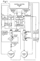
- a supply pump 1 pumps ink from a supply tank 3 to the droplet generator 5 of a printhead 7.
- Droplet generator 5 generates a plurality of streams of ink droplets 9, and a gutter 11 of the printhead 7 collects ink droplets not used in printing.
- a vacuum source 13 draws ink collected in gutter 11 to a return tank 15.
- a bleed connection 19 continuously bleeds ink from generator 5 to supply tank 3.
- the flow rate of the streams of ink droplets 9 is measured as follows.
- Ink level sensors 23, 25 are located respectively at levels A and B of supply tank 3.
- a central control system 21 measures the time it takes for the ink to fall from level A to level B. This provides a measure of the flow rate of the streams of ink droplets 9.
- the time taken for the ink level to drop from A to B provides an accurate measure of the flow rate of the streams of ink droplets 9 generated by generator 5.
- supply tank 3, droplet generator 5, and bleed connection 19 are in closed circuit, the rate of drop of ink level in supply tank 3 is an accurate representation of the flow rate of the streams of ink droplets 9 generated by generator 5.
- a transfer pump 17 pumps ink from return tank 15 via a non-return valve 45 to supply tank 3.
- control system 21 starts pump 17.
- control system 21 stops pump 17.
- the flow rate measurement of the previous paragraph is made by control system 21 when ink is not being pumped from return tank 15 to supply tank 3.
- the velocity of the streams of ink droplets 9 is maintained at a constant value. This is achieved by means of central control system 21 which maintains constant the composition, temperature, and pressure of the ink in droplet generator 5.
- an ink level sensor 27 is located at a top-up level in return tank 15.
- control system 21 opens valves 29 and 31 to reservoirs 33 and 35 respectively.
- Reservoir 33 contains the same ink as supplied to generator 5 but with a slightly lower proportion of ink solvent therein so that it is slightly more viscous.
- Reservoir 35 contains ink solvent.
- Vacuum source 13 draws into return tank 15 ink and ink solvent from reservoirs 33, 35.
- Control system 21 keeps open valves 29 and 31 for relative periods such that an ink of the same viscosity as that supplied to generator 5 resides in return tank 15, i.e.
- control system 21 To replace ink solvent which has evaporated in the course of printing or which has been added in the course of printing as a consequence of cleaning the printhead 7 with solvent, the flow rate measurement made using level sensors 23, 25 is used by control system 21 to determine whether to add ink solvent from reservoir 35 or thicker ink from reservoir 33. If the flow rate measurement made is less than the desired flow rate, the assumption is that ink solvent has been lost through evaporation, and hence control system 21 opens valve 31 so that ink solvent is drawn into return tank 15.
- control system 21 opens valve 29 so that thicker ink is drawn into return tank 15.
- any error in the relative mixing to replace ink used up in printing i.e. the relative mixing of ink and ink solvent from reservoirs 33, 35, will be corrected for by control system 21 in response to the flow rate measurements made using level sensors 23, 25.
- Central control system 21 maintains the temperature constant using a temperature sensor 37 to sense the temperature of the ink in generator 5, and a heater 39 and cooler 41 located in the ink supply path from supply pump 1 to generator 5. In dependence on the temperature sensed, operation of heater 39 and cooler 41 is controlled so that the desired ink temperature in generator 5 is maintained. In this connection it is to be appreciated that, since the presence of bleed connection 19 increases the ink flow rate to generator 5, it enhances temperature control, since there is less time between heater/cooler 39/41 and generator 5 during which cooling of the ink can occur.
- Central control system 21 maintains the pressure constant using a pressure sensor 43 to sense the pressure of the ink in generator 5. In dependence on the pressure sensed, the speed of supply pump 1 is adjusted so that the desired ink pressure in generator 5 is maintained.
- the velocity of the streams of ink droplets 9 is maintained constant by maintaining constant each of the composition, temperature, and pressure of the ink in droplet generator 5. It is to be appreciated that this velocity maintenance could also be achieved by allowing each of the composition, temperature, and pressure to vary within predefined limits, but to control this variation such that the result of the combination of all three parameters always results in the same desired velocity of the streams of ink droplets 9. The requirement is that the three parameters are controlled such that the velocity is maintained constant.
- the ink held in reservoir 33 need not be thicker than that supplied to generator 5, but could be of the same consistency.
- ink level in return tank 15 drops below the top-up level, only ink from reservoir 33 is supplied to return tank 15.
- valve 31 is opened to supply ink solvent from reservoir 35.
- ink from reservoir 33 is supplied.
- supply pump 1 could be replaced by a pressure source which applies pressure to the ink in supply tank 3 to force it out and around to generator 5. In this case a pump would be required in bleed connection 19.
- ink level in tanks 3, 15 could be achieved, not by means of sensors 23, 25, 27 located at fixed positions within tanks 3, 15, but by one sensor in each tank 3, 15 which floats on the surface of the ink and therefore changes level therewith.
- control system 21 opens valves 103, 109, 117 and 119, and closes valves 105, 107, 115, 121 and 111.
- ink in gutter 11 is drawn into return tank 15 by vacuum source 13; ink is continuously bled from droplet generator 5 to supply tank 3 via connection 19; and ink is pumped by supply pump 1 from supply tank 3 to droplet generator 5 via heater 39 and cooler 41.
- control system 21 Prior to printing by the system during start-up of the system, control system 21 opens valves 105, 107, 115 and 121, closes valves 103, 109, 117, 119 and 111, and switches valve 113 to connect to vacuum source 13 - valve 113 may be switched to connect holding tank 101 to either source 13 or atmospheric pressure.
- Supply pump 1 pumps ink solvent from reservoir 35 around flush path 123 to generator 5.
- the ink solvent which collects in gutter 11 is drawn into holding tank 101 by vacuum source 13.
- Solvent is also drawn by source 13 into holding tank 101 from bleed connection 19.
- Blockage may occur of the droplet forming nozzles of generator 5. This blockage may be removed by manually spraying onto the nozzles ink solvent, closing valve 109, opening valve 107, and switching valve 113 to vacuum source 13. Source 13 draws the ink solvent through the nozzles into generator 5 unblocking the nozzles, and then via bleed connection 19 and valve 107 to holding tank 101. Thus, the used ink solvent again resides in holding tank 101. Valves 115, 117, 119, 121 are closed during the operation so that printhead 7 may be switched to vacuum.
- this liquid may be used in printing by the system in place of the ink solvent in reservoir 35.
- liquid from holding tank 101 may be supplied to return tank 15 instead of ink solvent from reservoir 35.
- the liquid is supplied by switching valve 113 to atmospheric pressure, and opening valve 111 so that vacuum source 13 draws the liquid from holding tank 101 to return tank 15.
- the liquid residing in holding tank 101 may not be predominantly ink solvent.
- the temperature control afforded by temperature sensor 37 and heater/cooler 39/41 is removed, and the velocity of the streams of ink droplets 9 maintained constant by varying the ink composition to cater for ambient temperature change. If the ambient temperature of the print run prior to a present print run was significantly lower (or higher) than that of the present print run, then the composition of the ink in the system at the start of the present print run will be appreciably thinner (thicker) than that appropriate for the present print run. Thus, the system is initially run prior to printing to feed this thinner (thicker) ink into holding tank 101. This thinner (thicker) ink may then later during printing be supplied to return tank 15 when appropriate.
- holding tank 101 the purpose of holding tank 101 is to receive liquid that issues from droplet generator 5 during preparation of the system for subsequent printing, so that this liquid may then be used later during the subsequent printing when the conditions of the system are such that it is appropriate to use this liquid.
- the aforementioned flush cleaning of the system during shut-down can be considered preparation of the system for subsequent printing, since the cleaning takes place so that the system is not 'dirty' at the beginning of the next print run.
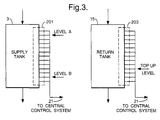
- level sensors 23 and 25 of supply tank 3 have been replaced by multi-level sensor 201, and level sensor 27 of return tank 15 has been replaced by multi-level sensor 203.
- a multi-level sensor comprises at least three level sensors, each of which detects whether liquid height is above or below the level at which it is located.
- the number of sensors used is such that they may be located with a frequency of one every 5 to 10mm of tank height.
- central control system 21 is able to determine the rate of fall/rise of liquid level in tanks 3, 15 respectively.
- Control sytem 21 monitors the determined rates, and, if either deviates by more than a predetermined amount from its expected value, provides an indication that there has been a fault in the printing system, and further provides an indication of what this fault is.
- control system 21 is able to provide an indication of what the fault is that has occurred.
- the occurrence of a particular type of fault is first given (i.e. it is first stated how a particular constituent element of the printing system is not operating as it should be); the effect(s) of the fault occurrence is/are then given; and finally the resultant rise/fall rate in supply tank 3/return tank 15 is given.
- valves 117, 119 If either of valves 117, 119 is stuck closed, the fall in ink level in supply tank 3 that would normally take place, will not. The ink level will remain the same. Thus, the fall rate in supply tank 3 will be zero. Further, gutter 11 will not be supplying unused ink to return tank 15. The rise in ink level in return tank 15 that would normally be taking place, will either not occur at all, if top-up via valves 29, 31, 111 is not taking place, or will occur more slowly. Thus, the rise rate in return tank 15 will either be zero or relatively low.
- valves 115, 121 If either of valves 115, 121 is stuck closed during flushing, the rise in liquid level in holding tank 101 that would normally take place, will not. The level will remain the same. Thus, the rise rate in holding tank 101 will be zero.
- valve 103 If valve 103 is stuck closed, the rise in ink level in return tank 15 that would normally be taking place, will either not occur at all, if top-up via valves 29, 31, 111 is not taking place, or will occur more slowly. Thus, the rise rate in return tank 15 will either be zero or relatively low.
- valve 105 or valve 107 If either valve 105 or valve 107 is stuck closed during flushing, the rise in liquid level in holding tank 101 that would normally be taking place due to the receipt of liquid via both valves 105 and 107, will only be taking place due to the receipt of liquid via one valve 105 or 107, and therefore will take place more slowly. Thus, the rise rate in holding tank 101 will be relatively low.
- valve 45 If valve 45 is stuck closed, the rise in ink level in supply tank 3 that would normally take place when transferring ink from return tank 15 to supply tank 3, will not take place. This ink level will be falling. Thus, the rise rate in supply tank 3 will be negative. Further, the fall in ink level in return tank 15 that would normally be taking place, will not. This level will be rising. Thus, the fall rate in return tank 15 will be negative.
- valves 29, 31, 111 If any one of valves 29, 31, 111 is stuck closed at a time it is instructed to be open, the top-up that would normally be received by return tank 15 via the stuck closed valve 29 or 31 or 111, will not be received, and hence the rise in ink level in return tank 15 will be slower than expected. Thus, the rise rate in return tank 15 will be relatively low.
- valve 105 If valve 105 is stuck open during printing, the rise in ink level in return tank 15 will occur more slowly than expected. Thus, the rise rate in return tank 15 will be relatively low.
- valve 107 If valve 107 is stuck open during printing, when transfer is not taking place from return tank 15 to supply tank 3, the fall in ink level in supply tank 3 will occur more quickly than expected. Thus, the fall rate in supply tank 3 will be relatively high. When transfer is taking place, the rise in ink level in supply tank 3 will occur more slowly than expected. Thus the rise rate in supply tank 3 will be relatively low. In both cases, i.e. not during and during transfer, there will be an unexpected rise in the level in holding tank 101. Thus, the rise rate in holding tank 101 will be positive.
- valve 113 If valve 113 is stuck at vacuum during printing, no top-up from holding tank 101 will be received by return tank 15 when valve 111 is opened. The level in return tank 15 will therefore rise more slowly than expected, and there will be no drop in the level in holding tank 101. Thus, the rise rate in return tank 15 will be relatively low, and the fall rate in holding tank 101 will be zero.
- valve 45 If valve 45 is stuck open when transfer is not required from return tank 15 to supply tank 3, there will be back flow due to the action of vacuum source 13. Hence the level in return tank 15 will be rising more quickly than expected, and the level in supply tank 3 will be falling more quickly than expected. Thus, both the rise rate in return tank 15 and the fall rate in supply tank 3 will be relatively high.
- valves 29, 31, 111 If any one of valves 29, 31, 111 is stuck open at a time it is instructed to be closed, a top-up that would not normally be received by return tank 15 at that time, will be received via stuck open valve 29 or 31 or 111. The level in return tank 15 will therefore rise more quickly than expected. Thus, the rise rate in return tank 15 will be relatively high.
- both the fall in level in return tank 15 and the rise in level in supply tank 3 will be slower than expected.
- both the fall rate in return tank 15 and the rise rate in supply tank 3 will be relatively low. This change in rate may be used to control the speed of transfer pump 17.
- gutter 11 is not collecting or is collecting little unused ink, during transfer from return tank 15 to supply tank 3 the level in return tank 15 will fall more quickly than expected. Thus, the fall rate in return tank 15 will be relatively high. When transfer is not taking place, assuming no top-up via valves 29, 31, 111, the level in return tank 15 will either not rise at all or will rise very slowly. Thus, the rise rate in return tank 15 will be zero or relatively very low.
- each of multi-level sensors 201, 203 could be replaced by a continuous level sensor which continuously provides to control system 21 measurement of liquid level.
- control system 21 may not be definitively determined by the rise/fall rate in supply tank 3/return tank 15, but may require the supply to control system 21 of other information regarding the condition of the printing system.
Landscapes
- Engineering & Computer Science (AREA)
- Quality & Reliability (AREA)
- Ink Jet (AREA)
- Particle Formation And Scattering Control In Inkjet Printers (AREA)
- Measurement Of Levels Of Liquids Or Fluent Solid Materials (AREA)
- Surgical Instruments (AREA)
Claims (8)
- Système d'impression à jet d'encre comportant : un générateur de gouttelette (5) destiné à générer au moins un courant de gouttelettes d'encre; un réservoir d'alimentation (3) destiné à délivrer de l'encre audit générateur (5); des moyens de transfert d'alimentation (1) destinés à entraíner l'encre dudit réservoir (3) vers ledit générateur (5); et des moyens de mesure (21, 22, 23) destinés à mesurer le débit du ou des courants de gouttelettes d'encre générés par ledit générateur (5) en contrôlant le changement de niveau d'encre dans ledit réservoir (3), ledit système comprenant une liaison d'appoint (19) dudit générateur (5) vers ledit réservoir (3) en circuit fermé avec ledit réservoir (3), la présence de ladite liaison d'appoint (19) augmentant ainsi le débit d'encre dudit réservoir (3) vers ledit générateur (5) sans affecter la mesure par lesdits des moyens de mesure (21, 22, 23) du débit du ou des courants de gouttelettes d'encre générés par ledit générateur (5).
- Système selon la revendication 1, comportant en outre : une gouttière (11) destinée à recueillir des gouttelettes d'encre inutilisées dans l'impression; un réservoir de retour (15) destiné à recevoir l'encre recueillie dans la gouttière (11); et des moyens de transfert de retour (17) destinés à entraíner de l'encre dudit réservoir de retour (15) vers ledit réservoir d'alimentation (3), les mesures de débit réalisées en contrôlant le changement de niveau d'encre dans ledit réservoir d'alimentation (3) étant réalisées lorsque l'encre n'est pas entraínée du réservoir de retour (15) vers le réservoir d'alimentation (3).
- Système selon la revendication 2, comportant en outre des moyens de commande (21) destinés à maintenir sensiblement constante la vitesse du ou des courants de gouttelettes d'encre générés par ledit générateur de gouttelette (5).
- Système selon la revendication 3, dans lequel lesdits moyens de commande (21) commandent la composition, la température et la pression de l'encre dans ledit générateur de gouttelette (5).
- Système selon la revendication 4, dans lequel lesdits moyens de commande (21) maintiennent sensiblement constante ladite composition, ladite température et ladite pression.
- Système selon la revendication 5, dans lequel lesdits moyens de commande (21) maintiennent sensiblement constante ladite composition en délivrant du solvant d'encre et de l'encre audit réservoir de retour (15), l'alimentation étant réalisée en fonction du niveau d'encre dans ledit réservoir de retour (15) et de la mesure de débit réalisée en contrôlant le changement de niveau d'encre dans ledit réservoir d'alimentation (3).
- Système selon la revendication 5 ou la revendication 6, dans lequel lesdits moyens de commande (21) maintiennent sensiblement constante ladite température en détectant la température de l'encre dans ledit générateur de gouttelette (5), et en réponse à cela, en ajustant la température de l'encre dans le passage d'encre dudit réservoir d'alimentation (3) vers ledit générateur de gouttelette (5).
- Système selon la revendication 5 ou la revendication 6 ou la revendication 7, dans lequel lesdits moyens de transfert d'alimentation (1) comportent une pompe (1) située dans le passage d'encre dudit réservoir d'alimentation (3) vers ledit générateur de gouttelette (5); et lesdits moyens de commande (21) maintiennent sensiblement constante ladite pression en détectant la pression de l'encre dans ledit générateur (5), et en réponse à cela, en ajustant la vitesse de fonctionnement de ladite pompe (1).
Priority Applications (2)
| Application Number | Priority Date | Filing Date | Title |
|---|---|---|---|
| EP99119651A EP0968828B1 (fr) | 1996-02-22 | 1997-02-20 | Système d'impression à jet d'encre |
| EP99119650A EP0968827B1 (fr) | 1996-02-22 | 1997-02-20 | Système d'impression à jet d'encre |
Applications Claiming Priority (3)
| Application Number | Priority Date | Filing Date | Title |
|---|---|---|---|
| GB9603813 | 1996-02-22 | ||
| GBGB9603813.8A GB9603813D0 (en) | 1996-02-22 | 1996-02-22 | An ink jet printing system |
| PCT/GB1997/000487 WO1997030850A1 (fr) | 1996-02-22 | 1997-02-20 | Systeme d'impression a jet d'encre |
Related Child Applications (2)
| Application Number | Title | Priority Date | Filing Date |
|---|---|---|---|
| EP99119650A Division EP0968827B1 (fr) | 1996-02-22 | 1997-02-20 | Système d'impression à jet d'encre |
| EP99119651A Division EP0968828B1 (fr) | 1996-02-22 | 1997-02-20 | Système d'impression à jet d'encre |
Publications (2)
| Publication Number | Publication Date |
|---|---|
| EP0891258A1 EP0891258A1 (fr) | 1999-01-20 |
| EP0891258B1 true EP0891258B1 (fr) | 2002-06-19 |
Family
ID=10789248
Family Applications (3)
| Application Number | Title | Priority Date | Filing Date |
|---|---|---|---|
| EP99119650A Expired - Lifetime EP0968827B1 (fr) | 1996-02-22 | 1997-02-20 | Système d'impression à jet d'encre |
| EP99119651A Expired - Lifetime EP0968828B1 (fr) | 1996-02-22 | 1997-02-20 | Système d'impression à jet d'encre |
| EP97905233A Expired - Lifetime EP0891258B1 (fr) | 1996-02-22 | 1997-02-20 | Systeme d'impression a jet d'encre |
Family Applications Before (2)
| Application Number | Title | Priority Date | Filing Date |
|---|---|---|---|
| EP99119650A Expired - Lifetime EP0968827B1 (fr) | 1996-02-22 | 1997-02-20 | Système d'impression à jet d'encre |
| EP99119651A Expired - Lifetime EP0968828B1 (fr) | 1996-02-22 | 1997-02-20 | Système d'impression à jet d'encre |
Country Status (8)
| Country | Link |
|---|---|
| US (1) | US6350021B1 (fr) |
| EP (3) | EP0968827B1 (fr) |
| JP (1) | JP2000504647A (fr) |
| AT (3) | ATE217262T1 (fr) |
| AU (1) | AU1885697A (fr) |
| DE (3) | DE69712529T2 (fr) |
| GB (1) | GB9603813D0 (fr) |
| WO (1) | WO1997030850A1 (fr) |
Families Citing this family (18)
| Publication number | Priority date | Publication date | Assignee | Title |
|---|---|---|---|---|
| GB2339170A (en) * | 1998-07-25 | 2000-01-19 | Markem Tech Ltd | Printhead with integral ink gutter |
| EP1142713B9 (fr) * | 1999-11-05 | 2010-07-21 | Seiko Epson Corporation | Dispositif d'impression de type jet d'encre, procede d'alimentation en encre de reservoir secondaire et procede d'evaluation de quantite d'encre fournie a ce reservoir par le meme dispositif |
| US6406125B1 (en) | 2000-06-08 | 2002-06-18 | Illinois Tool Works Inc. | System and method for maintaining the front of a fluid jet device in a relatively clean condition |
| EP1164022B1 (fr) | 2000-06-16 | 2008-07-30 | Canon Kabushiki Kaisha | Appareil d'enregistrement à jet d'encre utilisant un élément semi-conducteur solide |
| EP1780023B1 (fr) | 2000-10-31 | 2008-08-13 | Zipher Limited | Appareil d'impression |
| US6679590B2 (en) * | 2001-10-31 | 2004-01-20 | Scitex Digital Printing, Inc. | Shutdown for an ink jet printer |
| US6637862B2 (en) | 2002-02-08 | 2003-10-28 | Illinois Tool Works, Inc. | Maintenance module for fluid jet device |
| US6830320B2 (en) | 2002-04-24 | 2004-12-14 | Eastman Kodak Company | Continuous stream ink jet printer with mechanism for asymmetric heat deflection at reduced ink temperature and method of operation thereof |
| US6615004B1 (en) | 2002-05-06 | 2003-09-02 | Hewlett-Packard Development Company, L.P. | Supplying marking fluid in an imaging system |
| EP1827845B1 (fr) * | 2004-12-17 | 2010-09-22 | Agfa Graphics Nv | Dispositif de régénération de l'encre pour impression à jet d'encre |
| EP1841597A4 (fr) * | 2005-01-11 | 2010-01-27 | Jemtex Ink Jet Printing Ltd | Imprimante a jet d'encre et procede de commande |
| JP4305418B2 (ja) * | 2005-06-13 | 2009-07-29 | 株式会社ミヤコシ | インクジェット記録装置におけるインク供給装置 |
| JP5222564B2 (ja) * | 2008-01-04 | 2013-06-26 | 理想科学工業株式会社 | インク循環確認方法及びインク充填方法 |
| AT507445B1 (de) * | 2008-10-31 | 2011-09-15 | Durst Phototechnik Digital Technology Gmbh | Tintenversorgungssystem für einen tintenstrahldrucker |
| JP6139099B2 (ja) * | 2012-10-30 | 2017-05-31 | エスアイアイ・プリンテック株式会社 | 液体噴射ユニット、液体噴射ユニットの使用方法及び液体噴射装置 |
| JP6405822B2 (ja) * | 2014-09-17 | 2018-10-17 | 株式会社リコー | 液体塗布装置、および画像形成システム |
| DE102016106011A1 (de) * | 2016-04-01 | 2017-10-05 | Till Gmbh | Vorrichtung und Verfahren zur Tintenversorgung beim Digitaldruck |
| JP6604613B1 (ja) * | 2018-11-01 | 2019-11-13 | 紀州技研工業株式会社 | インクジェットプリンタ |
Family Cites Families (19)
| Publication number | Priority date | Publication date | Assignee | Title |
|---|---|---|---|---|
| US4121222A (en) | 1977-09-06 | 1978-10-17 | A. B. Dick Company | Drop counter ink replenishing system |
| FR2405819A1 (fr) | 1977-10-13 | 1979-05-11 | Dick Co Ab | Moyens pour l'alimentation en encre d'un dispositif d'impression par jet d'encre |
| EP0046385B1 (fr) | 1980-08-15 | 1985-11-21 | EASTMAN KODAK COMPANY (a New Jersey corporation) | Imprimante à jet d'encre, procédé pour l'arrêter, procédé de contrôle du flux d'encre, et système d'alimentation en encre de ladite imprimante |
| US4342042A (en) | 1980-12-19 | 1982-07-27 | Pitney Bowes Inc. | Ink supply system for an array of ink jet heads |
| US4413267A (en) | 1981-12-18 | 1983-11-01 | Centronics Data Computer Corp. | Ink supply system for ink jet printing apparatus |
| JPS5973957A (ja) * | 1982-10-20 | 1984-04-26 | Ricoh Co Ltd | インクジエツト記録装置におけるインク回収装置 |
| DE3428434C2 (de) * | 1983-08-02 | 1995-09-14 | Canon Kk | Druckvorrichtung |
| US4555709A (en) * | 1984-04-12 | 1985-11-26 | The Mead Corporation | Ink reconstitution system and method for ink drop printer |
| US4555712A (en) | 1984-08-03 | 1985-11-26 | Videojet Systems International, Inc. | Ink drop velocity control system |
| US4772900A (en) * | 1985-10-22 | 1988-09-20 | Canon Kabushiki Kaisha | Ink-jet recording apparatus |
| FR2619753B2 (fr) * | 1986-12-10 | 1990-08-31 | Imaje Sa | Circuit d'alimentation fluide d'une tete d'impression equipee d'une cellule multifonctions comportant une chambre a volume variable |
| ATE82196T1 (de) * | 1987-03-13 | 1992-11-15 | Jan Slomianny | Tintensystem fuer tintenstrahlmatrixdrucker. |
| GB8708884D0 (en) * | 1987-04-14 | 1987-05-20 | Domino Printing Sciences Plc | Control of ink jet printing system |
| US4827280A (en) | 1988-08-09 | 1989-05-02 | A. B. Dick Company | Flow rate control system |
| JPH035155A (ja) * | 1989-06-02 | 1991-01-10 | Canon Inc | 液体噴射記録装置および該装置用記録ヘッド |
| GB9009957D0 (en) | 1990-05-03 | 1990-06-27 | Domino Printing Sciences Plc | Ink supply system for continuous ink jet printer |
| DE4101695A1 (de) * | 1991-01-22 | 1992-08-13 | Agfa Gevaert Ag | Abdeck- und reinigungsvorrichtung fuer einen tintenspritzkopf |
| FR2685664B1 (fr) * | 1991-12-27 | 1994-12-23 | Imaje | Circuit d'alimentation multifluide d'une tete de projection de liquide et imprimante a jet d'encre utilisant un tel circuit. |
| JP3041499B2 (ja) * | 1994-01-20 | 2000-05-15 | 株式会社日立製作所 | インクジェット記録装置の配管装置 |
-
1996
- 1996-02-22 GB GBGB9603813.8A patent/GB9603813D0/en active Pending
-
1997
- 1997-02-20 AT AT99119651T patent/ATE217262T1/de not_active IP Right Cessation
- 1997-02-20 JP JP9529901A patent/JP2000504647A/ja not_active Ceased
- 1997-02-20 EP EP99119650A patent/EP0968827B1/fr not_active Expired - Lifetime
- 1997-02-20 DE DE69712529T patent/DE69712529T2/de not_active Expired - Fee Related
- 1997-02-20 WO PCT/GB1997/000487 patent/WO1997030850A1/fr not_active Ceased
- 1997-02-20 DE DE69713497T patent/DE69713497T2/de not_active Expired - Fee Related
- 1997-02-20 EP EP99119651A patent/EP0968828B1/fr not_active Expired - Lifetime
- 1997-02-20 EP EP97905233A patent/EP0891258B1/fr not_active Expired - Lifetime
- 1997-02-20 AU AU18856/97A patent/AU1885697A/en not_active Abandoned
- 1997-02-20 US US09/142,429 patent/US6350021B1/en not_active Expired - Fee Related
- 1997-02-20 AT AT99119650T patent/ATE212914T1/de not_active IP Right Cessation
- 1997-02-20 DE DE69710373T patent/DE69710373T2/de not_active Expired - Fee Related
- 1997-02-20 AT AT97905233T patent/ATE219424T1/de not_active IP Right Cessation
Also Published As
| Publication number | Publication date |
|---|---|
| EP0968827A3 (fr) | 2000-02-02 |
| EP0968828A2 (fr) | 2000-01-05 |
| EP0968828B1 (fr) | 2002-05-08 |
| EP0968827A2 (fr) | 2000-01-05 |
| DE69710373D1 (de) | 2002-03-21 |
| DE69712529T2 (de) | 2002-11-07 |
| DE69712529D1 (de) | 2002-06-13 |
| DE69710373T2 (de) | 2002-08-22 |
| WO1997030850A1 (fr) | 1997-08-28 |
| EP0968827B1 (fr) | 2002-02-06 |
| EP0891258A1 (fr) | 1999-01-20 |
| EP0968828A3 (fr) | 2000-02-02 |
| ATE212914T1 (de) | 2002-02-15 |
| DE69713497D1 (de) | 2002-07-25 |
| AU1885697A (en) | 1997-09-10 |
| US6350021B1 (en) | 2002-02-26 |
| JP2000504647A (ja) | 2000-04-18 |
| ATE219424T1 (de) | 2002-07-15 |
| DE69713497T2 (de) | 2003-03-06 |
| GB9603813D0 (en) | 1996-04-24 |
| ATE217262T1 (de) | 2002-05-15 |
Similar Documents
| Publication | Publication Date | Title |
|---|---|---|
| EP0891258B1 (fr) | Systeme d'impression a jet d'encre | |
| EP0170449B1 (fr) | Système de commande de la vitesse de goutelettes d'encre | |
| EP0076914B1 (fr) | Imprimantes à jet d'encre, comportant des systèmes de recirculation de l'encre | |
| US6357854B1 (en) | Ink jet printer having waste tank overflow prevention | |
| JP2000033710A (ja) | インク回路ならびにそのような回路を用いたインク噴射装置および調整装置またはコンベヤ | |
| EP0571784B1 (fr) | Système hydraulique pour imprimantes à jet d'encre continu | |
| US5714989A (en) | Inkdrop-volume test using heat-flow effects, for thermal-inkjet printers | |
| US5682183A (en) | Ink level sensor for an inkjet print cartridge | |
| US4856322A (en) | Method and device for measuring the viscosity of an ink | |
| US6789883B2 (en) | Method and apparatus for compensating for ink container extraction characteristics | |
| EP0082272A1 (fr) | Imprimantes à jet d'encre et méthodes pour manipuler de telles imprimantes | |
| GB2605788A (en) | Continuous inkjet printer | |
| CA2245590A1 (fr) | Systeme d'impression a jet d'encre | |
| EP3455078B1 (fr) | Perfectionnements apportés ou se rapportant aux imprimantes à jet d'encre continu | |
| US20250074067A1 (en) | Fluid delivery system | |
| CA2141194A1 (fr) | Imprimantes a jet d'encre et leurs methodes de fonctionnement | |
| EP0142265B1 (fr) | Systèmes hydrauliques pour imprimantes à jet d'encre | |
| WO2025052218A1 (fr) | Système de distribution de fluide | |
| GB2566628A (en) | Improvements in or relating to continuous inkjet printers |
Legal Events
| Date | Code | Title | Description |
|---|---|---|---|
| PUAI | Public reference made under article 153(3) epc to a published international application that has entered the european phase |
Free format text: ORIGINAL CODE: 0009012 |
|
| 17P | Request for examination filed |
Effective date: 19980916 |
|
| AK | Designated contracting states |
Kind code of ref document: A1 Designated state(s): AT BE CH DE DK ES FI FR GB GR IE IT LI LU MC NL PT SE |
|
| 17Q | First examination report despatched |
Effective date: 19990628 |
|
| GRAG | Despatch of communication of intention to grant |
Free format text: ORIGINAL CODE: EPIDOS AGRA |
|
| GRAG | Despatch of communication of intention to grant |
Free format text: ORIGINAL CODE: EPIDOS AGRA |
|
| GRAH | Despatch of communication of intention to grant a patent |
Free format text: ORIGINAL CODE: EPIDOS IGRA |
|
| RAP1 | Party data changed (applicant data changed or rights of an application transferred) |
Owner name: MARCONI DATA SYSTEMS INC. |
|
| GRAH | Despatch of communication of intention to grant a patent |
Free format text: ORIGINAL CODE: EPIDOS IGRA |
|
| GRAA | (expected) grant |
Free format text: ORIGINAL CODE: 0009210 |
|
| AK | Designated contracting states |
Kind code of ref document: B1 Designated state(s): AT BE CH DE DK ES FI FR GB GR IE IT LI LU MC NL PT SE |
|
| PG25 | Lapsed in a contracting state [announced via postgrant information from national office to epo] |
Ref country code: NL Free format text: LAPSE BECAUSE OF FAILURE TO SUBMIT A TRANSLATION OF THE DESCRIPTION OR TO PAY THE FEE WITHIN THE PRESCRIBED TIME-LIMIT Effective date: 20020619 Ref country code: LI Free format text: LAPSE BECAUSE OF FAILURE TO SUBMIT A TRANSLATION OF THE DESCRIPTION OR TO PAY THE FEE WITHIN THE PRESCRIBED TIME-LIMIT Effective date: 20020619 Ref country code: GR Free format text: LAPSE BECAUSE OF FAILURE TO SUBMIT A TRANSLATION OF THE DESCRIPTION OR TO PAY THE FEE WITHIN THE PRESCRIBED TIME-LIMIT Effective date: 20020619 Ref country code: FI Free format text: LAPSE BECAUSE OF FAILURE TO SUBMIT A TRANSLATION OF THE DESCRIPTION OR TO PAY THE FEE WITHIN THE PRESCRIBED TIME-LIMIT Effective date: 20020619 Ref country code: CH Free format text: LAPSE BECAUSE OF FAILURE TO SUBMIT A TRANSLATION OF THE DESCRIPTION OR TO PAY THE FEE WITHIN THE PRESCRIBED TIME-LIMIT Effective date: 20020619 Ref country code: BE Free format text: LAPSE BECAUSE OF FAILURE TO SUBMIT A TRANSLATION OF THE DESCRIPTION OR TO PAY THE FEE WITHIN THE PRESCRIBED TIME-LIMIT Effective date: 20020619 Ref country code: AT Free format text: LAPSE BECAUSE OF FAILURE TO SUBMIT A TRANSLATION OF THE DESCRIPTION OR TO PAY THE FEE WITHIN THE PRESCRIBED TIME-LIMIT Effective date: 20020619 |
|
| REF | Corresponds to: |
Ref document number: 219424 Country of ref document: AT Date of ref document: 20020715 Kind code of ref document: T |
|
| REG | Reference to a national code |
Ref country code: GB Ref legal event code: FG4D |
|
| REG | Reference to a national code |
Ref country code: CH Ref legal event code: EP |
|
| RAP2 | Party data changed (patent owner data changed or rights of a patent transferred) |
Owner name: VIDEOJET TECHNOLOGIES INC. |
|
| REG | Reference to a national code |
Ref country code: IE Ref legal event code: FG4D |
|
| REF | Corresponds to: |
Ref document number: 69713497 Country of ref document: DE Date of ref document: 20020725 |
|
| NLT2 | Nl: modifications (of names), taken from the european patent patent bulletin |
Owner name: VIDEOJET TECHNOLOGIES INC. |
|
| PG25 | Lapsed in a contracting state [announced via postgrant information from national office to epo] |
Ref country code: SE Free format text: LAPSE BECAUSE OF FAILURE TO SUBMIT A TRANSLATION OF THE DESCRIPTION OR TO PAY THE FEE WITHIN THE PRESCRIBED TIME-LIMIT Effective date: 20020919 Ref country code: DK Free format text: LAPSE BECAUSE OF FAILURE TO SUBMIT A TRANSLATION OF THE DESCRIPTION OR TO PAY THE FEE WITHIN THE PRESCRIBED TIME-LIMIT Effective date: 20020919 |
|
| PG25 | Lapsed in a contracting state [announced via postgrant information from national office to epo] |
Ref country code: PT Free format text: LAPSE BECAUSE OF FAILURE TO SUBMIT A TRANSLATION OF THE DESCRIPTION OR TO PAY THE FEE WITHIN THE PRESCRIBED TIME-LIMIT Effective date: 20020923 |
|
| ET | Fr: translation filed | ||
| NLV1 | Nl: lapsed or annulled due to failure to fulfill the requirements of art. 29p and 29m of the patents act | ||
| PG25 | Lapsed in a contracting state [announced via postgrant information from national office to epo] |
Ref country code: ES Free format text: LAPSE BECAUSE OF FAILURE TO SUBMIT A TRANSLATION OF THE DESCRIPTION OR TO PAY THE FEE WITHIN THE PRESCRIBED TIME-LIMIT Effective date: 20021220 |
|
| REG | Reference to a national code |
Ref country code: CH Ref legal event code: PL |
|
| PG25 | Lapsed in a contracting state [announced via postgrant information from national office to epo] |
Ref country code: LU Free format text: LAPSE BECAUSE OF NON-PAYMENT OF DUE FEES Effective date: 20030220 Ref country code: IE Free format text: LAPSE BECAUSE OF NON-PAYMENT OF DUE FEES Effective date: 20030220 |
|
| PG25 | Lapsed in a contracting state [announced via postgrant information from national office to epo] |
Ref country code: MC Free format text: LAPSE BECAUSE OF NON-PAYMENT OF DUE FEES Effective date: 20030228 |
|
| PLBE | No opposition filed within time limit |
Free format text: ORIGINAL CODE: 0009261 |
|
| STAA | Information on the status of an ep patent application or granted ep patent |
Free format text: STATUS: NO OPPOSITION FILED WITHIN TIME LIMIT |
|
| 26N | No opposition filed |
Effective date: 20030320 |
|
| REG | Reference to a national code |
Ref country code: IE Ref legal event code: MM4A |
|
| PGFP | Annual fee paid to national office [announced via postgrant information from national office to epo] |
Ref country code: FR Payment date: 20050208 Year of fee payment: 9 |
|
| PGFP | Annual fee paid to national office [announced via postgrant information from national office to epo] |
Ref country code: GB Payment date: 20050216 Year of fee payment: 9 |
|
| PGFP | Annual fee paid to national office [announced via postgrant information from national office to epo] |
Ref country code: DE Payment date: 20050217 Year of fee payment: 9 |
|
| PG25 | Lapsed in a contracting state [announced via postgrant information from national office to epo] |
Ref country code: IT Free format text: LAPSE BECAUSE OF NON-PAYMENT OF DUE FEES Effective date: 20050220 |
|
| PG25 | Lapsed in a contracting state [announced via postgrant information from national office to epo] |
Ref country code: GB Free format text: LAPSE BECAUSE OF NON-PAYMENT OF DUE FEES Effective date: 20060220 |
|
| PG25 | Lapsed in a contracting state [announced via postgrant information from national office to epo] |
Ref country code: DE Free format text: LAPSE BECAUSE OF NON-PAYMENT OF DUE FEES Effective date: 20060901 |
|
| GBPC | Gb: european patent ceased through non-payment of renewal fee |
Effective date: 20060220 |
|
| REG | Reference to a national code |
Ref country code: FR Ref legal event code: ST Effective date: 20061031 |
|
| PG25 | Lapsed in a contracting state [announced via postgrant information from national office to epo] |
Ref country code: FR Free format text: LAPSE BECAUSE OF NON-PAYMENT OF DUE FEES Effective date: 20060228 |