EP0891280B1 - Fermeture de boites de conserve non circulaires - Google Patents
Fermeture de boites de conserve non circulaires Download PDFInfo
- Publication number
- EP0891280B1 EP0891280B1 EP97908134A EP97908134A EP0891280B1 EP 0891280 B1 EP0891280 B1 EP 0891280B1 EP 97908134 A EP97908134 A EP 97908134A EP 97908134 A EP97908134 A EP 97908134A EP 0891280 B1 EP0891280 B1 EP 0891280B1
- Authority
- EP
- European Patent Office
- Prior art keywords
- clinching
- cover
- supporting
- lid
- profile
- Prior art date
- Legal status (The legal status is an assumption and is not a legal conclusion. Google has not performed a legal analysis and makes no representation as to the accuracy of the status listed.)
- Expired - Lifetime
Links
Images


Classifications
-
- B—PERFORMING OPERATIONS; TRANSPORTING
- B65—CONVEYING; PACKING; STORING; HANDLING THIN OR FILAMENTARY MATERIAL
- B65B—MACHINES, APPARATUS OR DEVICES FOR, OR METHODS OF, PACKAGING ARTICLES OR MATERIALS; UNPACKING
- B65B7/00—Closing containers or receptacles after filling
- B65B7/16—Closing semi-rigid or rigid containers or receptacles not deformed by, or not taking-up shape of, contents, e.g. boxes or cartons
- B65B7/28—Closing semi-rigid or rigid containers or receptacles not deformed by, or not taking-up shape of, contents, e.g. boxes or cartons by applying separate preformed closures, e.g. lids, covers
- B65B7/2842—Securing closures on containers
- B65B7/285—Securing closures on containers by deformation of the closure
- B65B7/2857—Securing closures on containers by deformation of the closure and the container rim
Definitions
- the invention relates to the field of packaging technology and the clinching process precedes a folding of the lid and fuselage edge.
- non-circular cans and especially elongated cans with straight side areas are increasingly thin sheets, for example made of aluminum. Examples are the classic ones deep-drawn fish cans. After filling such cans with the respective content the lid is usually clipped onto the lower part of the can, whereupon that Lower part of the can together with the lid of the sealing machine (folding machine) is fed.
- the cans are attached using a chain Carriers moved to the clinching station (and then further) while the Cover is moved towards the cans and onto them with the help of a second chain be put on.
- the cover chain then runs empty through the clinch rollers Clinchstation itself and is then returned. Therefore they are Options for supporting the lid from above are limited.
- the Clinch rollers because they are powerless, have to do this with high precision Point in time along the can at which the stamp is in the Lid core is located. Furthermore, the speed at which is successful and can be clinched without significant committee, clearly limited: if the Carrier releases the can, "slides" on the relatively smooth surface (a rougher would scratch the bottom of the can) due to the existing impulse a small one Uncontrolled route. Then she has to go back to the Normal speed can be accelerated. At high machine speeds the resulting inaccuracy increases due to the higher impulse.
- FR-A-2 584 675 already has a support disk which can be driven in the middle on its side Circumferentially arranged support elements known, the profile sole when clinching in the Immerse the mirror of the lid to be clipped on.
- this profile sole has one recess extending almost over the entire cover mirror, so that only a narrow circumferential area is available as an effective counter pressure element and therefore the bulging of the lid when clinching, especially in medium-sized ones Areas cannot be safely prevented.
- this object is achieved by a support disc according to claim 1 Clinching device according to claim 6 and the method according to claim 9 or 13 solved.
- the support disc can be driven in the middle and can be used with the drives for the Coupling clinch rollers, for example via a common shaft, the Drive forces are transferred from the shaft to the clinch rollers via a bevel gear drive can be and the support disc is driven directly by the shaft.
- the Lid transport chain will appear shortly after the place where you put the lid releases, led away and returned so that it does not run through the clinching station (Claim 6).
- the support disc can be used as a wheel or in another on a cylinder with relative low axial expansion based form.
- She points to hers Includes at least one support element, which in turn has a profile with the vertical forces that may be acting on the lid core from below can be effectively collected so that the lid does not bulge will (claim 1).
- the profile sole of the support element is shortened, so that each front and / or back in the more domed areas of the can Stay millimeter free.
- the support element can be in a specific configuration in the direction of Be undercut towards the center of the pane (claim 4).
- the width of the support elements (in the axial direction is preferably the Support disc) dimensioned so that the lid core completely or almost completely filled laterally becomes. So that the support disc can also absorb horizontal forces from the Clinching rolls when clinching and in the section of the lid edge in which each clinched will go out.
- each support element is a cylinder circumference segment educated. While the cans "drive” into the clinching station, the turns Support disc in the same direction as the linear movement of the can.
- the profile sole of the Support element is rolled on the can lid from front to back and comes thus in a strip which moves linearly on the cover (claim 8) the overall process considered to lie "over its entire surface of the cover", while the clinch rolls the straight long sides of the can in the same Clinch direction from front to back.
- the cans keep theirs Throughput speed essentially at.
- the drives for the clinch rollers are set so that the can when Clinching is accelerated slightly (claim 13). Scratches as a result of the changed This prevents loads resting on the driver.
- the support disk preferably has a plurality of support elements. For example, you can three support elements may be provided. The number actually chosen should be of scope the support disc and the distances with which the can bodies are guided, be made dependent. The disc is preferred with such Speed driven that a circumferential rotation divided by the number of Support elements corresponds exactly to the distance between two cans guided to the clinching station (Claim 12). The angular velocity of the tread soles should Support elements match the speed of the can run as possible.
- the support disc can be the support element (s) as an integral part contain. But it is also possible that the support elements are removably attached, so that when changing the can size the appropriate matching cans Support elements can be attached.
- the support elements can be used in such Cases attached via bolts, screws or the like.
- the support disc 1 is driven in the center, for example by means of a shaft, not shown here, which runs through the circular recess 2.
- the support disc is based on a substantially cylindrical shape with a radius R and a thickness or thickness between D and D '.
- each one Length L (in the circumferential direction) should be significantly less than that Lid core should be.
- the support elements 4, 4 ', 4 " have one opposite cylindrical inner shape of the support disc itself significantly widened Profile ("profile sole") 8,8 ', 8 ", which can be adapted to the dimensions of the respective lid core should.
- the three support elements are regularly spaced 120 ° apart, arranged.
- the profile soles have a length L of a little less than 60 °.
- the direction of rotation of the disc 1 is indicated by the arrow 5.
- the support elements 4 come first with the front part 6 on the Front part of the can lid mirror (strip 46 in Figure 4) to lie and then roll on the cover core running in the same direction up to the rear part 7 (strip 47 in Figure 4), while simultaneously clinching rollers 30,31 on the edge of the lid and can intervene along, caused by the linear linear movement v.
- the print is the edge of the recess 10a, 10b, 10c, 10d (short: 10) each shown in dashed lines and surrounded with a minor security edge or strip the cover ring 21. Also on both sides of the Profile sole 8 'recesses can be provided so that the direction of retracting can or the orientation of the supplied lid has no relevance.
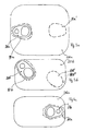
- the second exception area 10a ' is shown as an example in FIG. 3a. He is lying mirror-symmetrical to the central plane of the Can lid, which is shown in supervision in all figures 3.
- the position of the grip tab 21b is provided at an angle of approximately 45 °, the tear-open tab of the grip tab 21b pointing into the rounded corner region of the can lid 20b, which is smaller in area.
- a recess 1 Ob ' which in this case is rotationally symmetrical in the opposite corner and is oriented in this direction, which corresponds to the recess 1 Ob into which the grip tab 21b just fits.
- the recess 10b '(and also the recess 10b), if they protrude far into the rounded corner region, can also be extended completely into the corner region, which is illustrated by the dashed-line shape 10b ".
- FIG. 3c shows a polygonal shape of the recess 10c that fits the grip tab 21c, here the size of the recess and the remaining free space for the grip tab 21c are larger, due to the selected line sections that are composed, but the recess can more easily enter the profile sole 8 , 8 ', 8 "of the support element 4.
- the recess 10d is shown in FIG. 3d, with an associated tear-open handle 21d in the cover mirror (cover core) 20d.
- the recess 10 in FIG. 2 is therefore only a schematic illustration of all of the recesses explained in FIG. 3 and in each case dependent on the position, the direction and the shape of the mounting ring of the cover. Further small recesses can be provided if the cover carries elevations for stiffening, but they are small in relation to the total area of the profile sole.
- the cross-section of the profile sole 8 'in FIG. 2 can be clarified in more detail, with regard to the rearward-facing relocations 9a, 9b (Undercuts), which is a hat-shaped shape by a flat front Support area of the tread sole and a recessed intermediate support section define which opens into the inner disc 1 with diameter D '. That disc can once again in the middle, in its axial - the axis is at 100 designated - extent reduced to the attachment through the central opening 2 to facilitate.
- the reduced extent is D, the step over D ', the width of the Intermediate section of the support element 4 'and the even wider profile sole 8' in Axis direction 100 extended from the inside to the outside.
- the can which is shown in top view in FIG. 4, corresponds - as an example - to the can from FIG. 3b with a left to left upward and at an angle of approximately 45 °, the drawing ring 21b, which in the recess 10b of the Profile sole 8 fits.
- the profile sole 8 is in Figure 1 in a front region 6 and a rear area 7 shown, based on the direction of rotation 5. This front Area 6 engages with the lid 20b in FIG.
- the strip-shaped area 46 shifts during the movement the can, which has the linear movement v, over the cover mirror 20b and one Another snapshot is in Figure 4 in the rear part of the lid mirror 20b shown.
- the rollers 30, 31 clinch the same rollers that are not relocated which are only offset laterally to describe the linear movement of the can
- the rear area 7 also grips the strip Can lid, forms a support strip 47, as in the inlet area with the initial support strip 46 was the case; only in this momentary picture is that Support strips due to the design of the profile sole 8,8 ', 8 "continuously, because none Cover ring 21b is to be taken into account and the profile sole 8 here no recess 10b to have and does not have.
- the sliding of the strip S over the lid core 20b almost detects that the entire area of the lid core, not with regard to the snapshots at the same time, but via the movement of the can body through the Clinch station accumulated through.
- the surface area which is covered by this strip-shaped support zone S is designed such that the cover format of FIG. 3a has a support area of approximately 75% of the cover surface (without the second recess 10a '), that the shape of the Figure 3b has a coverage of about 60% (without the second recess 10b 'or 10b ") and that Figure 3c also reaches about 60% (slightly less) of area coverage, it should be noted that the smaller the lid surface, the Percentage of coverage is slightly reduced, but in any case remains above 50%, even with the smallest commercially available lid format, because the lid flap will always have a certain size (due to the size of the human finger) and is therefore covered takes up a larger space on the lid mirror 20 as a percentage of the lid size.
- the circumferential speed 5 at the height of the radius or diameter of the profile sole 8 is approximately the speed that the can has as speed v when it moves into the clinching station.
- the strip S shown in FIG. 4, the one arriving in two snapshots Stripe 46 and expiring stripe 47 is shown in its extension to the Interventions of the clinch rollers 30.31 to adjust. Due to the large radius R of the Support disc 1 is usually achieved a strip-shaped support area that is wider than a line (the hypothetically and purely mathematically the only connecting element a curved area with a plane that is tangent); this Support area will become wider (in the direction of advance of the can), the thinner and softer and therefore the more flexible the lid material and the higher the inside is the lid mirror 20b acting pressure. The bigger it will be, the bigger is the radius R of the support disc 1 and moves according to physical considerations at the same speed v over the lid as the can on the Clinch rolls past 30.31.
- the moving line drawn in dashed lines Strip S illustrates this in FIG. 4.
Landscapes
- Engineering & Computer Science (AREA)
- Mechanical Engineering (AREA)
- Closures For Containers (AREA)
- Auxiliary Devices For And Details Of Packaging Control (AREA)
- Control And Other Processes For Unpacking Of Materials (AREA)
Claims (13)
- Disque d'appui (1) servant à soutenir la surface de couvercle d'un couvercle lors du sertissage de boítes de conserve non rondes, ledit disquecaractérisé en ce que le profil de la base est réalisé sous forme de segment circonférentiel de cylindre avec un ou deux évidement(s) (10) en surface pour les languettes à arracher de telle manière que, au cours du roulage de la base profilée, pendant lequel toute la superficie de celle-ci vient en application sur la surface du couvercle, des forces verticales, qui agissent depuis l'intérieur sur la surface de couvercle lors du sertissage au niveau du bord, soient efficacement interceptées par des parties supplémentaires.(i) étant adapté à être entraíné (2) au centre ;(ii) étant basé sur une forme sensiblement cylindrique (R, D, D') ;(iii) présentant, au niveau de sa périphérie (3), au moins un élément de soutien (4, 4', 4"), dont la base profilée (8, 8', 8") est réalisée en tant que partie d'un segment circonférentiel de cylindre et qui est adapté, quant à sa forme, au couvercle à sertir chaque fois, afin de pouvoir soutenir, lors du sertissage, la surface du couvercle sur une partie de sa superficie, par ledit au moins un élément de soutien (4, 4', 4"),
- Disque d'appui selon la revendication 1, dans lequel ledit au moins un élément de soutien (4, 4', 4") est fixé, de manière amovible, au niveau de la périphérie (3).
- Disque d'appui selon l'une des revendications 1 et 2, dans lequel la base profilée (8, 8', 8") dudit au moins un élément de soutien (4, 4', 4") présente axialement une largeur non inférieure ou bien seulement à peine inférieure à la largeur de la surface de couvercle, tandis que, dans le sens de la périphérie (L) elle est nettement plus courte par rapport à la longueur de la surface de couvercle.
- Disque d'appui selon la revendication 3, dans lequel la dimension de la base profilée de l'élément de soutien est, dans le sens de la périphérie, chaque fois à l'avant (6) et à l'arrière (7) plus courte d'environ trois à sept millimètres que le corps de couvercle (surface de couvercle), et/ou la base profilée (8, 8', 8") comporte une contre-dépouille (9a, 9b) en direction de l'axe (100) du disque de support.
- Dispositif de sertissage pour le sertissage de boítes de conserve non rondes avec couvercle et corps de boíte, comprenant(a) une chaíne d'entraíneurs pour l'amenée des corps de boíte dans le poste de sertissage,(b) une chaíne d'entraíneurs pour l'amenée des couvercles de boíte sur les corps de boíte,(c) au moins deux galets de sertissage (30, 31), qui sont disposés de telle manière que la boíte puisse être assemblée par sertissage avec le couvercle, des deux côtés,(d) un disque de support (1, 3, 4, 4', 4") selon l'une des revendications 1 à 5, la chaíne d'entraíneurs pour l'amenée des couvercles de boíte ne passant pas dans la zone du poste de sertissage.
- Dispositif de sertissage selon la revendication 5, dans lequel les galets de sertissage (30, 31) sont entraínés.
- Dispositif de sertissage selon la revendication 6, dans lequel les galets de sertissage et le disque de support sont entraínés à l'aide d'un seul et même arbre.
- Procédé de sertissage de couvercles sur des boítes de conserve non rondes, chaque boíte étant guidée dans un poste de sertissage à une vitesse (v) restant sensiblement constante, tandis qu'au moins un élément de soutien (4, 4', 4") d'un disque de support (1) rotatif vient en appui sur la surface de couvercle, caractérisé en ce que des forces verticales, agissant depuis l'intérieur sur la surface de couvercle, sont efficacement interceptées par l'intermédiaire du profil de l'élément de soutien, selon l'une des revendications 1 à 4, par une bande (S ; 46, 47) de forme linéaire orientée transversalement au sens d'acheminement de boítes (v) et se déplaçant au-dessus de la surface de couvercle, cette bande s'étendant au niveau de galets de sertissage (30, 31) espacés et la bande (46, 47) étant interrompue dans la zone des languettes de préhension (21a, 21b ...) du couvercle, mais s'étendant sinon sensiblement à plat.
- Procédé selon l'une des revendications ci-dessus pour le procédé, dans lequel la bande est l'image de la base profilée (8, 8', 8"), courbe respective sur la surface de couvercle (20a, 20b) dans une large mesure plate.
- Procédé selon l'une des revendications précédentes, dans lequel la base profilée (8, 8', 8") comporte un renfoncement dans la zone (10) des languettes de préhension (21a, 21b) d'un couvercle de boíte de conserve, mais est sinon réalisée pratiquement plane de telle manière que, au cours du roulement de la base sur la surface de couvercle (20a, 20b), plus de 50 % de la superficie du couvercle, et notamment plus de 60 % de celle-ci, soient en contact avec elle.
- Procédé selon l'une des revendications 8 à 10, lorsque le sertissage (du côté du bord) s'effectue, à l'aide de galets de sertissage (30, 31) entraínés, avec une rainure de sertissage.
- Procédé selon l'une des revendications 8 à 11, dans lequel le disque de support porte plusieurs éléments de soutien (4, 4', 4") et dans lequel l'intervalle temporel entre deux boítes, qui sont introduites successivement dans le poste de sertissage, est coordonné à la vitesse angulaire (5) du disque de support (1) de telle manière que le disque de support tourne pendant ce temps d'un angle de 360°, divisé par le nombre des éléments de soutien.
- Procédé selon l'une des revendications 8 à 12, dans lequel la vitesse périphérique, à laquelle se déplace au moins une base profilée (8, 8', 8") dudit au moins un élément de soutien (4, 4', 4") du disque de support (1), est identique ou légèrement supérieure à la vitesse linéaire (v) de l'avancement des boítes de conserve.
Applications Claiming Priority (5)
| Application Number | Priority Date | Filing Date | Title |
|---|---|---|---|
| DE29604478U DE29604478U1 (de) | 1996-03-11 | 1996-03-11 | Clincheinrichtung zum Clinchen unrunder Dosen sowie Stützscheibe hierfür |
| DE19609506 | 1996-03-11 | ||
| DE1996109506 DE19609506A1 (de) | 1996-03-11 | 1996-03-11 | Verfahren zum Clinchen unrunder Dosen sowie Stützscheibe hierfür |
| DE29604478U | 1996-03-11 | ||
| PCT/DE1997/000477 WO1997033793A1 (fr) | 1996-03-11 | 1997-03-11 | Fermeture de boites de conserve non circulaires |
Publications (2)
| Publication Number | Publication Date |
|---|---|
| EP0891280A1 EP0891280A1 (fr) | 1999-01-20 |
| EP0891280B1 true EP0891280B1 (fr) | 2000-07-12 |
Family
ID=26023676
Family Applications (1)
| Application Number | Title | Priority Date | Filing Date |
|---|---|---|---|
| EP97908134A Expired - Lifetime EP0891280B1 (fr) | 1996-03-11 | 1997-03-11 | Fermeture de boites de conserve non circulaires |
Country Status (5)
| Country | Link |
|---|---|
| EP (1) | EP0891280B1 (fr) |
| AT (1) | ATE194564T1 (fr) |
| DE (2) | DE59702011D1 (fr) |
| DK (1) | DK0891280T3 (fr) |
| WO (1) | WO1997033793A1 (fr) |
Family Cites Families (2)
| Publication number | Priority date | Publication date | Assignee | Title |
|---|---|---|---|---|
| FR2584675B3 (fr) * | 1985-07-15 | 1987-10-09 | Mecanique Sarl Ste Nle | Dispositif de tassage et d'agrafage de fonds ou couvercles sur boites de conserve |
| DE29604478U1 (de) * | 1996-03-11 | 1996-06-20 | Schmalbach-Lubeca Ag, 38112 Braunschweig | Clincheinrichtung zum Clinchen unrunder Dosen sowie Stützscheibe hierfür |
-
1997
- 1997-03-11 DK DK97908134T patent/DK0891280T3/da active
- 1997-03-11 AT AT97908134T patent/ATE194564T1/de not_active IP Right Cessation
- 1997-03-11 DE DE59702011T patent/DE59702011D1/de not_active Expired - Fee Related
- 1997-03-11 EP EP97908134A patent/EP0891280B1/fr not_active Expired - Lifetime
- 1997-03-11 DE DE19780206T patent/DE19780206D2/de not_active Expired - Fee Related
- 1997-03-11 WO PCT/DE1997/000477 patent/WO1997033793A1/fr not_active Ceased
Also Published As
| Publication number | Publication date |
|---|---|
| DE59702011D1 (de) | 2000-08-17 |
| DK0891280T3 (da) | 2000-11-06 |
| EP0891280A1 (fr) | 1999-01-20 |
| ATE194564T1 (de) | 2000-07-15 |
| DE19780206D2 (de) | 1999-05-12 |
| WO1997033793A1 (fr) | 1997-09-18 |
Similar Documents
| Publication | Publication Date | Title |
|---|---|---|
| EP0200087B1 (fr) | Procédé et dispositif pour la fabrication d'emballages avec des arêtes arrondies ou biseautées | |
| DE2500569C2 (de) | Vorrichtung zum Verpacken von Gegenständen in ein Hüllmaterial | |
| EP2470430B1 (fr) | Dispositif permettant un étiquetage sur deux côtés ou plus | |
| EP0878398A1 (fr) | Procédé et dispositif pour plier le rabat terminal d'un flan pour une boíte à cigarettes | |
| EP1103369B1 (fr) | Procédé et dispositif pour la fabrication de collerettes pour des boítes avec un couvercle à charnière | |
| DE1928032A1 (de) | Verfahren und Vorrichtung zum Foerdern und Verpacken von Waren | |
| EP2783993B1 (fr) | Dispositif d'étiquetage des récipients et procédé de commande du dispositif d'étiquetage des récipients | |
| EP1717147B1 (fr) | Procédé et dispositif pour fermer une boîte en carton pliante pendant son convoyage continu | |
| EP3585602B1 (fr) | Arrangement de manipulation et de pliage et procédé de dépliage et d'introduction d'un élément de subdivision dans un suremballage | |
| DE8215209U1 (de) | Verschlußkappe | |
| EP0677473B1 (fr) | Dispositif pour plier ou similaire de cahiers de feuilles | |
| EP0891280B1 (fr) | Fermeture de boites de conserve non circulaires | |
| DE3905214A1 (de) | Verfahren und vorrichtung zur entnahme von (packungs-)zuschnitten aus einem zuschnitt-magazin | |
| EP1858767B1 (fr) | Couvercle a ouverture facile et son procede de production | |
| DE3637112A1 (de) | Verfahren und vorrichtung zum automatischen verpacken einer zerbrechlichen ware in einer faltschachtel | |
| EP0525614B1 (fr) | Procédé pour la fabrication de conteneurs en plastiques et conteneurs ainsi produits | |
| DE69411908T2 (de) | Vorrichtung zum verpacken in faltschachteln | |
| DE3231128C2 (de) | Verfahren zum Etikettieren aufrecht stehender Gefäße | |
| DE19609506A1 (de) | Verfahren zum Clinchen unrunder Dosen sowie Stützscheibe hierfür | |
| DE2731900A1 (de) | Vorrichtung und verfahren zum verpacken von einheiten in behaeltern | |
| DE3545838C2 (fr) | ||
| DE3128328C2 (fr) | ||
| DE29604478U1 (de) | Clincheinrichtung zum Clinchen unrunder Dosen sowie Stützscheibe hierfür | |
| DE2223787A1 (de) | Verkaufsumhuellung, sowie verfahren und vorrichtung zu deren weiterverarbeitung | |
| DE1909119A1 (de) | Maschine zum Aufstellen von Schachteln |
Legal Events
| Date | Code | Title | Description |
|---|---|---|---|
| PUAI | Public reference made under article 153(3) epc to a published international application that has entered the european phase |
Free format text: ORIGINAL CODE: 0009012 |
|
| 17P | Request for examination filed |
Effective date: 19980930 |
|
| AK | Designated contracting states |
Kind code of ref document: A1 Designated state(s): AT BE CH DE DK ES FI FR GB GR IE IT LI LU MC NL PT SE |
|
| AX | Request for extension of the european patent |
Free format text: LT PAYMENT 980930;LV PAYMENT 980930 |
|
| 17Q | First examination report despatched |
Effective date: 19990129 |
|
| GRAG | Despatch of communication of intention to grant |
Free format text: ORIGINAL CODE: EPIDOS AGRA |
|
| RAP1 | Party data changed (applicant data changed or rights of an application transferred) |
Owner name: MAIKO ENGINEERING GMBH |
|
| GRAG | Despatch of communication of intention to grant |
Free format text: ORIGINAL CODE: EPIDOS AGRA |
|
| GRAH | Despatch of communication of intention to grant a patent |
Free format text: ORIGINAL CODE: EPIDOS IGRA |
|
| GRAH | Despatch of communication of intention to grant a patent |
Free format text: ORIGINAL CODE: EPIDOS IGRA |
|
| GRAA | (expected) grant |
Free format text: ORIGINAL CODE: 0009210 |
|
| AK | Designated contracting states |
Kind code of ref document: B1 Designated state(s): AT BE CH DE DK ES FI FR GB GR IE IT LI LU MC NL PT SE |
|
| AX | Request for extension of the european patent |
Free format text: LT PAYMENT 19980930;LV PAYMENT 19980930 |
|
| LTIE | Lt: invalidation of european patent or patent extension | ||
| PG25 | Lapsed in a contracting state [announced via postgrant information from national office to epo] |
Ref country code: FI Free format text: LAPSE BECAUSE OF FAILURE TO SUBMIT A TRANSLATION OF THE DESCRIPTION OR TO PAY THE FEE WITHIN THE PRESCRIBED TIME-LIMIT Effective date: 20000712 Ref country code: ES Free format text: THE PATENT HAS BEEN ANNULLED BY A DECISION OF A NATIONAL AUTHORITY Effective date: 20000712 |
|
| REF | Corresponds to: |
Ref document number: 194564 Country of ref document: AT Date of ref document: 20000715 Kind code of ref document: T |
|
| REG | Reference to a national code |
Ref country code: CH Ref legal event code: EP |
|
| REG | Reference to a national code |
Ref country code: IE Ref legal event code: FG4D Free format text: GERMAN |
|
| REF | Corresponds to: |
Ref document number: 59702011 Country of ref document: DE Date of ref document: 20000817 |
|
| ITF | It: translation for a ep patent filed | ||
| GBT | Gb: translation of ep patent filed (gb section 77(6)(a)/1977) |
Effective date: 20000911 |
|
| PG25 | Lapsed in a contracting state [announced via postgrant information from national office to epo] |
Ref country code: SE Free format text: LAPSE BECAUSE OF FAILURE TO SUBMIT A TRANSLATION OF THE DESCRIPTION OR TO PAY THE FEE WITHIN THE PRESCRIBED TIME-LIMIT Effective date: 20001012 Ref country code: PT Free format text: LAPSE BECAUSE OF FAILURE TO SUBMIT A TRANSLATION OF THE DESCRIPTION OR TO PAY THE FEE WITHIN THE PRESCRIBED TIME-LIMIT Effective date: 20001012 |
|
| ET | Fr: translation filed | ||
| PG25 | Lapsed in a contracting state [announced via postgrant information from national office to epo] |
Ref country code: GR Free format text: LAPSE BECAUSE OF FAILURE TO SUBMIT A TRANSLATION OF THE DESCRIPTION OR TO PAY THE FEE WITHIN THE PRESCRIBED TIME-LIMIT Effective date: 20001013 |
|
| REG | Reference to a national code |
Ref country code: CH Ref legal event code: NV Representative=s name: KELLER & PARTNER PATENTANWAELTE AG |
|
| REG | Reference to a national code |
Ref country code: DK Ref legal event code: T3 |
|
| PG25 | Lapsed in a contracting state [announced via postgrant information from national office to epo] |
Ref country code: LU Free format text: LAPSE BECAUSE OF NON-PAYMENT OF DUE FEES Effective date: 20010311 Ref country code: GB Free format text: LAPSE BECAUSE OF NON-PAYMENT OF DUE FEES Effective date: 20010311 Ref country code: DK Free format text: LAPSE BECAUSE OF NON-PAYMENT OF DUE FEES Effective date: 20010311 Ref country code: AT Free format text: LAPSE BECAUSE OF NON-PAYMENT OF DUE FEES Effective date: 20010311 |
|
| PG25 | Lapsed in a contracting state [announced via postgrant information from national office to epo] |
Ref country code: IE Free format text: LAPSE BECAUSE OF NON-PAYMENT OF DUE FEES Effective date: 20010312 |
|
| PG25 | Lapsed in a contracting state [announced via postgrant information from national office to epo] |
Ref country code: MC Free format text: LAPSE BECAUSE OF NON-PAYMENT OF DUE FEES Effective date: 20010331 Ref country code: LI Free format text: LAPSE BECAUSE OF NON-PAYMENT OF DUE FEES Effective date: 20010331 Ref country code: CH Free format text: LAPSE BECAUSE OF NON-PAYMENT OF DUE FEES Effective date: 20010331 Ref country code: BE Free format text: LAPSE BECAUSE OF NON-PAYMENT OF DUE FEES Effective date: 20010331 |
|
| PLBE | No opposition filed within time limit |
Free format text: ORIGINAL CODE: 0009261 |
|
| STAA | Information on the status of an ep patent application or granted ep patent |
Free format text: STATUS: NO OPPOSITION FILED WITHIN TIME LIMIT |
|
| 26N | No opposition filed | ||
| BERE | Be: lapsed |
Owner name: MAIKO ENGINEERING G.M.B.H. Effective date: 20010331 |
|
| PG25 | Lapsed in a contracting state [announced via postgrant information from national office to epo] |
Ref country code: NL Free format text: LAPSE BECAUSE OF NON-PAYMENT OF DUE FEES Effective date: 20011001 |
|
| GBPC | Gb: european patent ceased through non-payment of renewal fee |
Effective date: 20010311 |
|
| REG | Reference to a national code |
Ref country code: CH Ref legal event code: PL |
|
| REG | Reference to a national code |
Ref country code: DK Ref legal event code: EBP |
|
| PG25 | Lapsed in a contracting state [announced via postgrant information from national office to epo] |
Ref country code: FR Free format text: LAPSE BECAUSE OF NON-PAYMENT OF DUE FEES Effective date: 20011130 |
|
| NLV4 | Nl: lapsed or anulled due to non-payment of the annual fee |
Effective date: 20011001 |
|
| REG | Reference to a national code |
Ref country code: FR Ref legal event code: ST |
|
| PG25 | Lapsed in a contracting state [announced via postgrant information from national office to epo] |
Ref country code: DE Free format text: LAPSE BECAUSE OF NON-PAYMENT OF DUE FEES Effective date: 20020101 |
|
| REG | Reference to a national code |
Ref country code: IE Ref legal event code: MM4A |
|
| PG25 | Lapsed in a contracting state [announced via postgrant information from national office to epo] |
Ref country code: IT Free format text: LAPSE BECAUSE OF NON-PAYMENT OF DUE FEES Effective date: 20050311 |