EP0891446B1 - Hilfsvorrichtung für eine verlegung von insbesondere betonformsteinen - Google Patents
Hilfsvorrichtung für eine verlegung von insbesondere betonformsteinen Download PDFInfo
- Publication number
- EP0891446B1 EP0891446B1 EP97920632A EP97920632A EP0891446B1 EP 0891446 B1 EP0891446 B1 EP 0891446B1 EP 97920632 A EP97920632 A EP 97920632A EP 97920632 A EP97920632 A EP 97920632A EP 0891446 B1 EP0891446 B1 EP 0891446B1
- Authority
- EP
- European Patent Office
- Prior art keywords
- shaped
- shaped strip
- strip according
- concrete
- area
- Prior art date
- Legal status (The legal status is an assumption and is not a legal conclusion. Google has not performed a legal analysis and makes no representation as to the accuracy of the status listed.)
- Expired - Lifetime
Links
- 238000009434 installation Methods 0.000 claims description 18
- 239000000853 adhesive Substances 0.000 claims description 17
- 238000004519 manufacturing process Methods 0.000 claims description 7
- 239000000463 material Substances 0.000 claims description 6
- 239000000945 filler Substances 0.000 claims description 4
- 238000000926 separation method Methods 0.000 claims description 4
- 230000015572 biosynthetic process Effects 0.000 claims description 2
- 230000000694 effects Effects 0.000 claims description 2
- 230000001464 adherent effect Effects 0.000 claims 3
- 230000001747 exhibiting effect Effects 0.000 claims 2
- 230000001154 acute effect Effects 0.000 claims 1
- 239000003795 chemical substances by application Substances 0.000 claims 1
- 150000001875 compounds Chemical class 0.000 claims 1
- 238000010276 construction Methods 0.000 claims 1
- 229920001021 polysulfide Polymers 0.000 claims 1
- 238000007789 sealing Methods 0.000 claims 1
- 238000000465 moulding Methods 0.000 description 57
- 230000001070 adhesive effect Effects 0.000 description 16
- 239000004575 stone Substances 0.000 description 9
- 239000000565 sealant Substances 0.000 description 5
- 238000005266 casting Methods 0.000 description 4
- 239000002131 composite material Substances 0.000 description 4
- 238000001035 drying Methods 0.000 description 3
- 239000006260 foam Substances 0.000 description 2
- 239000010410 layer Substances 0.000 description 2
- 206010023230 Joint stiffness Diseases 0.000 description 1
- 239000012790 adhesive layer Substances 0.000 description 1
- 230000002411 adverse Effects 0.000 description 1
- 239000010426 asphalt Substances 0.000 description 1
- 230000003749 cleanliness Effects 0.000 description 1
- 238000011109 contamination Methods 0.000 description 1
- 238000010586 diagram Methods 0.000 description 1
- 208000018459 dissociative disease Diseases 0.000 description 1
- 239000013013 elastic material Substances 0.000 description 1
- 238000011065 in-situ storage Methods 0.000 description 1
- 239000007788 liquid Substances 0.000 description 1
- 238000005192 partition Methods 0.000 description 1
- 230000001681 protective effect Effects 0.000 description 1
- 230000007704 transition Effects 0.000 description 1
- 230000032258 transport Effects 0.000 description 1
Images


Classifications
-
- E—FIXED CONSTRUCTIONS
- E01—CONSTRUCTION OF ROADS, RAILWAYS, OR BRIDGES
- E01C—CONSTRUCTION OF, OR SURFACES FOR, ROADS, SPORTS GROUNDS, OR THE LIKE; MACHINES OR AUXILIARY TOOLS FOR CONSTRUCTION OR REPAIR
- E01C19/00—Machines, tools or auxiliary devices for preparing or distributing paving materials, for working the placed materials, or for forming, consolidating, or finishing the paving
- E01C19/50—Removable forms or shutterings for road-building purposes; Devices or arrangements for forming individual paving elements, e.g. kerbs, in situ
- E01C19/502—Removable forms or shutterings, e.g. side forms; Removable supporting or anchoring means therefor, e.g. stakes
-
- E—FIXED CONSTRUCTIONS
- E01—CONSTRUCTION OF ROADS, RAILWAYS, OR BRIDGES
- E01C—CONSTRUCTION OF, OR SURFACES FOR, ROADS, SPORTS GROUNDS, OR THE LIKE; MACHINES OR AUXILIARY TOOLS FOR CONSTRUCTION OR REPAIR
- E01C11/00—Details of pavings
- E01C11/02—Arrangement or construction of joints; Methods of making joints; Packing for joints
-
- E—FIXED CONSTRUCTIONS
- E01—CONSTRUCTION OF ROADS, RAILWAYS, OR BRIDGES
- E01C—CONSTRUCTION OF, OR SURFACES FOR, ROADS, SPORTS GROUNDS, OR THE LIKE; MACHINES OR AUXILIARY TOOLS FOR CONSTRUCTION OR REPAIR
- E01C11/00—Details of pavings
- E01C11/22—Gutters; Kerbs ; Surface drainage of streets, roads or like traffic areas
- E01C11/221—Kerbs or like edging members, e.g. flush kerbs, shoulder retaining means ; Joint members, connecting or load-transfer means specially for kerbs
- E01C11/222—Raised kerbs, e.g. for sidewalks ; Integrated or portable means for facilitating ascent or descent
-
- E—FIXED CONSTRUCTIONS
- E01—CONSTRUCTION OF ROADS, RAILWAYS, OR BRIDGES
- E01C—CONSTRUCTION OF, OR SURFACES FOR, ROADS, SPORTS GROUNDS, OR THE LIKE; MACHINES OR AUXILIARY TOOLS FOR CONSTRUCTION OR REPAIR
- E01C11/00—Details of pavings
- E01C11/22—Gutters; Kerbs ; Surface drainage of streets, roads or like traffic areas
- E01C11/221—Kerbs or like edging members, e.g. flush kerbs, shoulder retaining means ; Joint members, connecting or load-transfer means specially for kerbs
- E01C11/223—Kerb-and-gutter structures; Kerbs with drainage openings channel or conduits, e.g. with out- or inlets, with integral gutter or with channel formed into the kerb ; Kerbs adapted to house cables or pipes, or to form conduits
-
- E—FIXED CONSTRUCTIONS
- E01—CONSTRUCTION OF ROADS, RAILWAYS, OR BRIDGES
- E01C—CONSTRUCTION OF, OR SURFACES FOR, ROADS, SPORTS GROUNDS, OR THE LIKE; MACHINES OR AUXILIARY TOOLS FOR CONSTRUCTION OR REPAIR
- E01C11/00—Details of pavings
- E01C11/22—Gutters; Kerbs ; Surface drainage of streets, roads or like traffic areas
- E01C11/224—Surface drainage of streets
- E01C11/227—Gutters; Channels ; Roof drainage discharge ducts set in sidewalks
- E01C11/229—Shallow gutters, i.e. gutters forming a minor pothole
-
- E—FIXED CONSTRUCTIONS
- E01—CONSTRUCTION OF ROADS, RAILWAYS, OR BRIDGES
- E01C—CONSTRUCTION OF, OR SURFACES FOR, ROADS, SPORTS GROUNDS, OR THE LIKE; MACHINES OR AUXILIARY TOOLS FOR CONSTRUCTION OR REPAIR
- E01C5/00—Pavings made of prefabricated single units
- E01C5/003—Pavings made of prefabricated single units characterised by material or composition used for beds or joints; characterised by the way of laying
-
- E—FIXED CONSTRUCTIONS
- E01—CONSTRUCTION OF ROADS, RAILWAYS, OR BRIDGES
- E01C—CONSTRUCTION OF, OR SURFACES FOR, ROADS, SPORTS GROUNDS, OR THE LIKE; MACHINES OR AUXILIARY TOOLS FOR CONSTRUCTION OR REPAIR
- E01C9/00—Special pavings; Pavings for special parts of roads or airfields
- E01C9/002—Coverings, the surface of which consists partly of prefabricated units and partly of sections made in situ
Definitions
- the invention relates to a molding for forming Parting lines according to the preamble of claim 1.
- US-A-1 891 897; US-A-3 838 930 and US-A-3 330 187 are used in the manufacture of concrete road surfaces Moldings known, which are surrounded on both sides by cast concrete and partially or completely after it has hardened are removable. This creates a parting line that with a bitumen layer or the like up to the upper edge area can be fully poured out.
- the invention has for its object a molding to create that with easy handling for education exact joints between concrete blocks and one Cast concrete usable area can be used, which then with high filling accuracy with a sealant can.
- the molding according to the invention enables a location and Form-accurate separation joint formation with function-optimized in each case Surface contours of the cast side surfaces.
- the molding is on the one hand towards the concrete blocks with a holding area and / or system profiling and on the other hand with the cast floor space a molded projection, so that with these cross-sectional profiles the exact definition of the form bar in the installation position, especially at the edge of a paving, is possible.
- With different joint connection areas to the adjacent usable area Installation conditions is quick and flexible Profile adjustment in the area of the form projection achievable.
- the molding consists of Plastic material on which in the area of the concrete block long side face with an adhesive provided adhesive area is defined so that precise positioning and stable positioning of the Form bar in the installed position is possible until the adjacent usable area is hardened. After that the The molding bar is gripped and removed from a handle attachment deducted from the installation position. The remaining joint points to Usable area towards an edge profile corresponding to the shape projection on, their altitude relative to Surface of the concrete block through the molding or the position of the integrated molded projection can be determined can.
- the one-piece molding be directly connected to concrete blocks.
- the Molded bar can be used as a detachable component on each or more of the side surface areas of concrete blocks fixed via an adhesive connection or the like so that together with the concrete block (s) is to be handled and placed in the installation position becomes.
- a cast concrete in particular can be used to Form bar are worked on that outside in front of the Concrete block the joint and a driving surface are formed their frontal edge-edge profile immediately of a smooth outer contact surface and that Form projection of the molding is formed.
- a driving surface are formed their frontal edge-edge profile immediately of a smooth outer contact surface and that Form projection of the molding is formed.
- Hardening of the fresh concrete and then the molding on the smooth contact surface with little effort and without additional aids are deducted.
- the molding consists of a suitable design several mediating through different adhesive forces Adhesive connections connected plastic parts, the outer, with its contact surface facing the cast concrete Part especially as a dimensionally stable PVC strip is trained. At least this part of the molding can after the positioning of the stone in the installation position and the hardening of the cast concrete be that precise and uniform Partition between the concrete block and the cast Driving surface is formed.
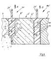
- Fig. 1 is a generally designated 1 and as Laying aid effective molding in the installed position shown, on the one hand a concrete block 2 and on the other border a usable area 3 formed from cast concrete.
- the molding 1 is in the area of the concrete blocks 2 directed first long side surface 4 in a connecting level E connected to the concrete block 2 and on the other hand, the molding 1 has in the area of it second longitudinal side surface 5 into the usable surface 3 transition shape projection 6.
- the molding 1 ' is in the area its first long side surface 4 with a support shoulder 7 provided that the concrete block 2 at least in some areas overlaps.
- a largely arbitrary component length Form bar 1 (Fig. 1) be connected so that the two Components can be positioned together in the installation position are.
- the molding 1 is particularly with the outer Side surface 8 of the concrete block 2 glued. It is also conceivable to shape the concrete block 2 such a molding 1 at least partially in the Mold cast concrete so that a particularly stable Connection of these as composite components to the installation location transporting embarrassment is reached.
- the molding 1 (Fig. 1) has one essentially rectangular cross-sectional contour, being more expedient Execution of the outer side surface 5 of the molding 1 in Area towards the top cover surface 11 with an acute-angled one Provided triangular shape projection 6 is.
- the molding 1 is in this first embodiment formed as a multi-part component that on a in Installation position of the lower foam base part 13 side by side both a foam filler 14 and an outer molded part 15 has. These individual layer parts 13, 14 and 15 are in this case via a respective adhesive connection A, B, C connected. It is of functional importance that the outer molded part 15 both in the area of its connection A to the base part 13 and the connection B to the filler part 14 towards with a defined tensile force releasable connection stability is set.
- this molding 1 for example of the in-situ concrete forming the driving surface 3 encapsulated
- the outer molding 15 with the molding 6 causes profiling of the cast concrete and this increased break resistance in the area of the joint edge having.
- the cast concrete After the cast concrete has hardened, it can Outer molded part 15 from this connection position Tensile forces (arrow F) are extracted, the comparatively low connection stability in areas A and B is overcome.
- the filling part 14 is in an expedient execution from one elastic material with comparatively small thickness D manufactured and can simultaneously with the outer molded part 15th be removed from the installation position, the connection B remains and the connection E to stone 2 and the connection C to the base part 13 are released. After that is a corresponding to the cross section of the outer molded part 15 Parting line created that contoured very precisely is and with little effort with one example Filled filler provided as a sealant can be.
- the molding 1 is in the Connection level E provided with a film part 16, the for example via an adhesive connection 17 on the base part 13 is set.
- this film part 16 After curing the Cast concrete of the driving surface 3 effective predetermined breaking notch Kind of a leading slot created over the Material stresses of the adjacent concrete parts under Avoidance of cracks in the driving surface be dismantled and thus neither the driving surface 3 nor the Joint tightness are adversely affected.
- the molding 1 ' is in a second Embodiment shown as a one-piece component on the one hand the joint molding 21 with the molding projection 6 and on the other hand via a connection zone 22 in passes the support profile approach 7, the manner of a cover leg 23 rests on the one hand on the shaped concrete block 2 and on the other hand a substantially vertically extending one Handle leg 24 forms.
- a handle leg 24 corresponding handle part 24 'is in Fig. 1 on Filling part 14 is provided, the outer molded part also being conceivable 15 also with a simplifying its handling Approach.
- the molding 1 ' is in the area of the cover leg 23 on the underside with the adhesive surface area 25 formed, for example at this point a releasable adhesive connection is provided. It is also conceivable that the adhesive surface area 25 the entire Length of the support lug 7 takes or similar to that 1 the adhesive surface on the side surface 4 is provided.
- the molding 1 ' has in a practical training on it to the concrete block 2 facing side surface 4 a a bevel 27 or the like. Stone contour corresponding profiling the connection zone 22 on and below the joint molding 21, an additional base part 13 can be provided be like that after pulling off the molding 1 ' 1 remains in the joint.
- the molding 1 ' is preferably with a horizontal top peeling surface 26 the top surface 11 provided.
- This contour 26 is in the Production of the usable area 3 from cast concrete is advantageous as Reference edge for one intended for pulling off the cast concrete Tool (not shown) can be used.
- Distance dimensions H and K (Fig. 3, Fig. 4) related to one shown with a dash-dotted line middle installation level L, are different variants a height adjustment of the peeling surface 26 (or the same level with this extending usable area 3) to the top 27 of the concrete block 2 shown.
- the Form bar 1 and its largely variable cross-sectional profile design is the intended height of the usable area 3 towards the concrete block 2 with high accuracy achievable, while the installation conditions are essential are simplified.
- this is at the lower edge area the molding 1 'located film part 16' in addition with the base part 13 'via an upper adhesive zone 31 forming adhesive layer 30 (Fig. 2) connected with the one in a lower area of the side surface 8 at the same time a connection of the film part 16 'with the concrete block 2 is formed via a second adhesive zone 32. So that the side surface 8 is above this second adhesive zone 32 to a vertical area 8 ', the chamfer area 27 and the adhesive surface area 25 are covered in such a way that contamination of the concrete block in this area 2 is largely avoided and when casting the Usable area 3 a clean joint is formed. simultaneously is the handle portion 24 like a flow wall in this Effective manufacturing phase and thus the cleanliness in the area the stone top even under harsh operating conditions guaranteed when casting the usable area 3.
- FIGS. 5 to 7 show respective end views of the cross-sectional design further moldings 101, 101 ', 201, that in the area of their longitudinal side surfaces 4 'or 5' with a Support profiling 40, 41 having shape recesses or 42 are provided.
- a concrete block 2 '(Fig. 8) or when pouring the usable area 3 a liquid concrete can be introduced, so that this after curing with an indissoluble connection of the respective molding 101, 101 ', 201 forms.
- FIG. 5 and 6 are the support profiles 40, 41 provided with several groove profiles 43, to the bottom area of the molding 101, 101 'into a forming lug 44 forming the laying gap, 44 'pass over and is in the embodiment according to FIG. 7 the support profile 42 only in the area of the long side surface 4 'provided, this with a single Arch groove 46 is designed in the manner of an abutment, which merges into a shape approach 45 on the bottom.
- the molding strips 101, 101 'according to FIGS. 5 and 6 are above their support profiles 40 or 41 with a respective division zone 47 so that the in the installed position located moldings 101, 101 '(Fig. 8) in the area zone 47 provided as a predetermined breaking line Effect of the tensile force introduced via the handle part 24 ' F can be separated and the upper part 15 'of Molded bars 101, 101 'are each pulled out of the installed position can be while the lower part 13 'with the respective Support profiles 40, 41, 42 in a connecting position is fixed to the concrete.
- a slot 48 is provided as the division zone, so that the molding 201 under the action of the tensile force F are separated in a residual connection area 49 can and then this upper part 15 'of the molding 201 is removable.
- the installation position (Fig. 8) remains the lower part 13 ' kind of an elastic intermediate part in the bottom area of a joint formed above (not shown).
- This fugue can with a sealant, such as one after Curing elastic plastic so to be poured out that this in the area of the side surface 5 and the connecting surface E 'an adhesive bond with the concrete material forms and also in the area of zone 47 at the lower part 13 ' liable.
- the moldings 101 are and 101 'in connection position with the molded block 2' and of the usable area 3, in particular the connecting areas E 'and E "to stone 2' formed thereby may be that in the manufacture of the concrete block 2 'in the mold (not shown) the two Moldings 101, 101 'are inserted and these together harden with the cast concrete to the concrete block 2 'in such a way that afterwards the two parts can be removed as a composite part, this a drying and hardening of the stone 2 can be fed and transported together to the installation location are. It is also conceivable for the molding 101, 101 ', 201 To be provided as one-piece frame parts that the concrete block 2 'during and after casting on all sides in the composite position include.
- the concrete block is 2 'during the drying phase before drying out on one side protected and there may be disadvantageous cracks, for example by unevenly setting the Cast concrete, can be prevented.
- Transportes form those located on the concrete block 2 ' Moldings 101, 101 ', 201 is a protective element with which in particular the fragile edges of the stone 2 ' Damage is protected.
Landscapes
- Engineering & Computer Science (AREA)
- Architecture (AREA)
- Civil Engineering (AREA)
- Structural Engineering (AREA)
- Road Paving Structures (AREA)
Description
- Fig. 1
- eine vergrößerte Ausschnittsdarstellung der in Einbaulage zwischen einem Betonformstein und einer Fahrfläche befindlichen Formleiste in mehrteiliger Ausführung,
- Fig. 2
- eine teilweise geschnittene Perspektivdarstellung der Formleiste in einer zweiten Ausführungsform in Einbaulage,
- Fig. 3 und Fig. 4
- jeweilige Seitenansichten der Formleiste ähnlich Fig. 2 mit unterschiedlichen Profilierungen an den Seitenflächen der Formleiste,
- Fig. 5 bis Fig. 7
- jeweilige Ausführungsformen der Formleiste mit einer Stützprofilierung an den Längsseitenflächen, und
- Fig. 8
- eine Prinzipdarstellung ähnlich Fig. 1 mit der Formleiste gemäß Fig. 5 bzw. Fig. 6 in Einbaulage.
Claims (17)
- Formleiste zur Bildung von Trennfugen zwischen Betonformsteinen (2, 2', 2") und einer Gießbeton-Nutzfläche (3), dadurch gekennzeichnet, daß die Formleiste (1; 1'; 101; 101'; 201) an ihrer zu den Betonformsteinen (2; 2'; 2") hin gerichteten ersten Längsseitenfläche (4; 4') mit einem Haltebereich versehen ist, bei dem in einem Haftflächenbereich (E; E'; E") ein die Formleiste (1, 1'; 101; 101'; 201) lösbar an den Betonformsteinen (2) festlegendes Klebmittel vorgesehen ist, und die Formleiste (1, 1'; 101; 101'; 201) an der zur Nutzfläche (3) hin gerichteten zweiten Längsseitenfläche (5; 5') einen eine spitzwinklige Dreiecksform aufweisenden Formvorsprung (6) aufweist, der eine fasenförmige Profilierung des Gießbetons bewirkt.
- Formleiste nach Anspruch 1, dadurch gekennzeichnet, daß die Formleiste (1; 1'; 101; 101'; 201) an ihrer zu den Betonformsteinen (2; 2'; 2") hin gerichteten ersten Längsseitenfläche (4; 4') mit einem die Einbaulage vorgebenden Anlageprofil (7, 7') versehen ist.
- Formleiste nach Anspruch 1 oder 2, dadurch gekennzeichnet, daß die Formleiste (1; 1') an ihrer Unterseite mit einem in Einbaulage am Betonformstein (2) anliegenden Folienstreifen (16; 16') versehen ist.
- Formleiste nach einem der Ansprüche 1 bis 3, dadurch gekennzeichnet, daß die Formleiste (1) im oberen Bereich mit einem einen Fließwall für den Gießbeton bildenden Griffteil (24; 24') versehen ist.
- Formleiste nach einem der Ansprüche 1 bis 4, dadurch gekennzeichnet, daß die Formleiste (1'; 101; 101'; 201) einstückig ausgebildet ist und ein zu den Betonformsteinen (2; 2') hin gerichtetes, einer Fase (27) o. dgl. Steinkontur entsprechendes Anlageprofil (7') aufweist.
- Formleiste nach Anspruch 5, dadurch gekennzeichnet, daß das Anlageprofil (7') einen auf der Oberflächenkontur (27') der Betonformsteine (2) aufliegenden Deckschenkel (23) umfaßt.
- Formleiste nach einem der Ansprüche 1 bis 6, dadurch gekennzeichnet, daß an die Formleiste (1'; 101; 101'; 201) oberseitig ein vertikaler Griffschenkel (24; 24') als der Griffteil angeformt ist.
- Formleiste nach einem der Ansprüche 1 bis 7, dadurch gekennzeichnet, daß die Formleiste (1; 1'; 101; 101'; 201) an der Oberseite des zur angrenzenden Nutzfläche (3) gerichteten Formvorsprungs (6) eine waagerechte Abziehfläche (26) aufweist.
- Formleiste nach einem der Ansprüche 1 bis 8, dadurch gekennzeichnet, daß die Abziehfläche (26) zum Griffschenkel (24) hin mit einer Schräge (22) übergeht.
- Formleiste nach einem der Ansprüche 1 bis 9, dadurch gekennzeichnet, daß der einen Haftflächenbereich (25) aufweisende Deckschenkel (23) in einer Ebene liegt, die bezogen auf eine von der waagerechten Abziehfläche (26) definierten Verlegeebene (L) in einem Höhenabstand (H) verläuft.
- Formleiste nach einem der Ansprüche 1 bis 10, dadurch gekennzeichnet, daß der Deckschenkel (23) mit einem die Oberflächenkontur (27') des Betonformsteins (2) nach Art eines Widerlagers hintergreifenden Profilansatz (28) versehen ist.
- Formleiste nach einem der Ansprüche 1 bis 11, dadurch gekennzeichnet, daß die Formleiste (101, 101', 201) im Bereich der ersten (4') und/oder der zweiten Längssteitenfläche (5') mit einer Stützprofilierung (40, 41, 42) versehen ist.
- Formleiste nach einem der Ansprüche 1 bis 12, dadurch gekennzeichnet, daß die Formleiste (101, 101' 201) mit einer Sollbruchzone (47) versehen ist.
- Formleiste nach Anspruch 13, dadurch gekennzeichnet, daß die Sollbruchzone (47) als eine Schlitzung (48) ausgebildet ist.
- Formleiste nach einem der Ansprüche 1 bis 14, dadurch gekennzeichnet, daß deren oberer Teil (15') durch Trennung im Bereich der Sollbruchzone (47) aus der Trennfuge herausziehbar ist, und diese mittels eines bis zur Kontur des Formvorsprungs (6) eingefüllten Polysulfid-Dichtmittels fluiddicht abgedichtet ist, wobei dieses über eine Verbindung zum Betonstein (2; 2'; 2'') und zum Gießbeton hin eine Zwei-Flanken-Haftung bildet.
- Formleiste nach einem der Ansprüche 1 bis 15, dadurch gekennzeichnet, daß die Formleiste (1) in mehrteiliger Ausbildung mit einem unteren Schaumsteff-Basisteil (13), einem auf diesem abgestützten und den Haftflächenbereich (E) aufweisenden Schaumstoff-Füllteil (14) sowie einem neben diesem auf dem Basisteil (13) angeordneten und einen Formvorsprung (6) aufweisenden Außenformteil (15) versehen ist.
- Formleiste nach einem der Ansprüche 1 bis 16, dadurch gekennzeichnet, daß die Formleiste (101; 101') bei der Herstellung des Betonformsteines (2') mit diesem zu einem einstückigen Verbundbauteil verbunden ist.
Applications Claiming Priority (5)
| Application Number | Priority Date | Filing Date | Title |
|---|---|---|---|
| DE29606557U | 1996-04-11 | ||
| DE29606557 | 1996-04-11 | ||
| DE29622081U DE29622081U1 (de) | 1996-04-11 | 1996-12-19 | Hilfsvorrichtung für eine Verlegung von insbesondere Betonformsteinen |
| DE29622081U | 1996-12-19 | ||
| PCT/EP1997/001759 WO1997038167A1 (de) | 1996-04-11 | 1997-04-09 | Hilfsvorrichtung für eine verlegung von insbesondere betonformsteinen |
Publications (2)
| Publication Number | Publication Date |
|---|---|
| EP0891446A1 EP0891446A1 (de) | 1999-01-20 |
| EP0891446B1 true EP0891446B1 (de) | 2003-11-12 |
Family
ID=26058840
Family Applications (1)
| Application Number | Title | Priority Date | Filing Date |
|---|---|---|---|
| EP97920632A Expired - Lifetime EP0891446B1 (de) | 1996-04-11 | 1997-04-09 | Hilfsvorrichtung für eine verlegung von insbesondere betonformsteinen |
Country Status (4)
| Country | Link |
|---|---|
| EP (1) | EP0891446B1 (de) |
| AT (1) | ATE254216T1 (de) |
| AU (1) | AU2694797A (de) |
| WO (1) | WO1997038167A1 (de) |
Families Citing this family (5)
| Publication number | Priority date | Publication date | Assignee | Title |
|---|---|---|---|---|
| WO2000061868A1 (fr) * | 1999-04-07 | 2000-10-19 | Nihon Kogyo Co., Ltd. | Pave et procede de pose correspondant |
| US10024023B2 (en) | 2015-04-28 | 2018-07-17 | Mono Slab Ez Form Llc | Cement form apparatus and method |
| US10024024B2 (en) | 2015-04-28 | 2018-07-17 | Mono Slab Ez Form Llc | Cement form with breakaway portion |
| US11105094B2 (en) * | 2019-09-16 | 2021-08-31 | Mono Slab Ez Form Llc | Cement form with extension |
| US11946266B2 (en) * | 2020-05-07 | 2024-04-02 | Mono Slab Ez Form Llc | Cement form with brick ledge |
Family Cites Families (7)
| Publication number | Priority date | Publication date | Assignee | Title |
|---|---|---|---|---|
| US1891897A (en) * | 1926-05-13 | 1932-12-20 | Carey Philip Mfg Co | Crowning device for expansion joints |
| US2012370A (en) * | 1932-07-21 | 1935-08-27 | Banwell James | Paving strip |
| DE632734C (de) * | 1934-11-17 | 1936-07-13 | Georg Wieland | Verfahren und Vorrichtung zum Herstellen von Raumfugen, insbesondere in Betonstrassendecken |
| US3330187A (en) * | 1964-12-14 | 1967-07-11 | Western Textile Products Compa | Plastic articles and methods of making same |
| US3838930A (en) * | 1971-11-26 | 1974-10-01 | V Koch | Two-piece joint-forming device for hardenable, area-covering structural material |
| DE3133271A1 (de) * | 1981-08-22 | 1983-03-03 | Irbit Holding AG, 1701 Fribourg | Zu einer rolle aufgewickelter schaumstoff-streifen, vorzugsweise zu abdichtungszwecken |
| BE898930A (fr) * | 1984-02-17 | 1984-06-18 | Moot Willem H | Joint de retrait ou de dilatation multi-directionnel |
-
1997
- 1997-04-09 AU AU26947/97A patent/AU2694797A/en not_active Abandoned
- 1997-04-09 EP EP97920632A patent/EP0891446B1/de not_active Expired - Lifetime
- 1997-04-09 AT AT97920632T patent/ATE254216T1/de not_active IP Right Cessation
- 1997-04-09 WO PCT/EP1997/001759 patent/WO1997038167A1/de not_active Ceased
Also Published As
| Publication number | Publication date |
|---|---|
| WO1997038167A1 (de) | 1997-10-16 |
| ATE254216T1 (de) | 2003-11-15 |
| AU2694797A (en) | 1997-10-29 |
| EP0891446A1 (de) | 1999-01-20 |
Similar Documents
| Publication | Publication Date | Title |
|---|---|---|
| DE3853418T2 (de) | Rahmen zum formen von fussbodenziegeln. | |
| DE2455020A1 (de) | Verfahren und vorrichtung zur herstellung einer abgedichteten fuge zwischen zwei benachbarten betonplatten o. dgl. | |
| DE3503395A1 (de) | Vorrichtung zur bildung von dehnungsfugen in estrich- oder betonflaechen | |
| DE2935392A1 (de) | Rohr mit einer mit einem schutzelement versehenen dichtflaeche | |
| EP0891446B1 (de) | Hilfsvorrichtung für eine verlegung von insbesondere betonformsteinen | |
| CH676943A5 (de) | ||
| DE3220256C2 (de) | ||
| DE2252408C3 (de) | Verfahren und Vorrichtungen zur Herstellung eines vorgefertigten Wandteiles aus Glasbausteinen | |
| DE9403780U1 (de) | Pflaster | |
| EP0003720B2 (de) | Verfahren zum rissicheren, dichten Anschluss eines Asphaltbelages an einen Bauteil, Satz von Profilen zur Durchführung dieses Verfahrens und nach dem Verfahren erstellte Baukonstruktion | |
| EP0343209A1 (de) | Vorrichtung zur überbrückung von dehnungsfugen | |
| DE3836883C2 (de) | ||
| DE7929663U1 (de) | Streifen zur rissinduzierung und abdichtung in beton | |
| DE29622081U1 (de) | Hilfsvorrichtung für eine Verlegung von insbesondere Betonformsteinen | |
| DE2249879B2 (de) | U-förmige Dehnfugenleiste für einen Estrich und Verfahren zu deren Einbau | |
| DE2553242A1 (de) | Verfahren zur ausbildung von dehnungsfugen in einer betonplatte und dehnungsfugenprofil | |
| DE2749481A1 (de) | Kantenschutz fuer eine abdeckplatte und verfahren zur herstellung eines solchen kantenschutzes | |
| DE3028207C2 (de) | Verfahren zum Herstellen einer Kernkastenabdichtung | |
| DE3634630C2 (de) | ||
| DD240923A1 (de) | Fugeneinlagen fuer betonstrassendecken oder dgl. | |
| DE1953380C2 (de) | Eckstück für elastische, profilförmige Dichtungseinlagen in winklig verlaufenden Dehnungsfugen von Fahrbahndecken od. dgl | |
| DE2918362C2 (de) | Verfahren zum Herstellen einer wasserdichten und korrosionsfesten Verbindung | |
| DE2046400A1 (de) | Verfahren zum Herstellen einer Dehnungsfugenüberbrückung in Verkehrswegen, Brücken, Parkdecks oder dgl | |
| EP1409796B1 (de) | Verfahren zum herstellen einer gedämpften schachtabdeckung | |
| DE19646641B4 (de) | Verfahren zum Sanieren von beschädigten Ecken an Stein- oder Betonplatten |
Legal Events
| Date | Code | Title | Description |
|---|---|---|---|
| PUAI | Public reference made under article 153(3) epc to a published international application that has entered the european phase |
Free format text: ORIGINAL CODE: 0009012 |
|
| 17P | Request for examination filed |
Effective date: 19981028 |
|
| AK | Designated contracting states |
Kind code of ref document: A1 Designated state(s): AT BE CH DE DK ES FR GB IT LI LU NL PT SE |
|
| 17Q | First examination report despatched |
Effective date: 20020712 |
|
| GRAH | Despatch of communication of intention to grant a patent |
Free format text: ORIGINAL CODE: EPIDOS IGRA |
|
| GRAS | Grant fee paid |
Free format text: ORIGINAL CODE: EPIDOSNIGR3 |
|
| GRAA | (expected) grant |
Free format text: ORIGINAL CODE: 0009210 |
|
| AK | Designated contracting states |
Kind code of ref document: B1 Designated state(s): AT BE CH DE DK ES FR GB IT LI LU NL PT SE |
|
| PG25 | Lapsed in a contracting state [announced via postgrant information from national office to epo] |
Ref country code: NL Free format text: LAPSE BECAUSE OF FAILURE TO SUBMIT A TRANSLATION OF THE DESCRIPTION OR TO PAY THE FEE WITHIN THE PRESCRIBED TIME-LIMIT Effective date: 20031112 Ref country code: IT Free format text: LAPSE BECAUSE OF FAILURE TO SUBMIT A TRANSLATION OF THE DESCRIPTION OR TO PAY THE FEE WITHIN THE PRE;WARNING: LAPSES OF ITALIAN PATENTS WITH EFFECTIVE DATE BEFORE 2007 MAY HAVE OCCURRED AT ANY TIME BEFORE 2007. THE CORRECT EFFECTIVE DATE MAY BE DIFFERENT FROM THE ONE RECORDED.SCRIBED TIME-LIMIT Effective date: 20031112 Ref country code: GB Free format text: LAPSE BECAUSE OF FAILURE TO SUBMIT A TRANSLATION OF THE DESCRIPTION OR TO PAY THE FEE WITHIN THE PRESCRIBED TIME-LIMIT Effective date: 20031112 Ref country code: FR Free format text: LAPSE BECAUSE OF FAILURE TO SUBMIT A TRANSLATION OF THE DESCRIPTION OR TO PAY THE FEE WITHIN THE PRESCRIBED TIME-LIMIT Effective date: 20031112 |
|
| REG | Reference to a national code |
Ref country code: GB Ref legal event code: FG4D Free format text: NOT ENGLISH |
|
| REG | Reference to a national code |
Ref country code: CH Ref legal event code: EP |
|
| REF | Corresponds to: |
Ref document number: 59710998 Country of ref document: DE Date of ref document: 20031218 Kind code of ref document: P |
|
| PG25 | Lapsed in a contracting state [announced via postgrant information from national office to epo] |
Ref country code: SE Free format text: LAPSE BECAUSE OF FAILURE TO SUBMIT A TRANSLATION OF THE DESCRIPTION OR TO PAY THE FEE WITHIN THE PRESCRIBED TIME-LIMIT Effective date: 20040212 Ref country code: DK Free format text: LAPSE BECAUSE OF FAILURE TO SUBMIT A TRANSLATION OF THE DESCRIPTION OR TO PAY THE FEE WITHIN THE PRESCRIBED TIME-LIMIT Effective date: 20040212 |
|
| PG25 | Lapsed in a contracting state [announced via postgrant information from national office to epo] |
Ref country code: ES Free format text: LAPSE BECAUSE OF FAILURE TO SUBMIT A TRANSLATION OF THE DESCRIPTION OR TO PAY THE FEE WITHIN THE PRESCRIBED TIME-LIMIT Effective date: 20040223 |
|
| REG | Reference to a national code |
Ref country code: CH Ref legal event code: NV Representative=s name: PATENTANWAELTE FELDMANN & PARTNER AG |
|
| PG25 | Lapsed in a contracting state [announced via postgrant information from national office to epo] |
Ref country code: LU Free format text: LAPSE BECAUSE OF NON-PAYMENT OF DUE FEES Effective date: 20040409 |
|
| PG25 | Lapsed in a contracting state [announced via postgrant information from national office to epo] |
Ref country code: BE Free format text: LAPSE BECAUSE OF NON-PAYMENT OF DUE FEES Effective date: 20040430 |
|
| NLV1 | Nl: lapsed or annulled due to failure to fulfill the requirements of art. 29p and 29m of the patents act | ||
| GBV | Gb: ep patent (uk) treated as always having been void in accordance with gb section 77(7)/1977 [no translation filed] |
Effective date: 20031112 |
|
| PLBE | No opposition filed within time limit |
Free format text: ORIGINAL CODE: 0009261 |
|
| STAA | Information on the status of an ep patent application or granted ep patent |
Free format text: STATUS: NO OPPOSITION FILED WITHIN TIME LIMIT |
|
| BERE | Be: lapsed |
Owner name: *KORTMANN KARL Effective date: 20040430 |
|
| 26N | No opposition filed |
Effective date: 20040813 |
|
| EN | Fr: translation not filed | ||
| REG | Reference to a national code |
Ref country code: CH Ref legal event code: PFA Owner name: KORTMANN, KARL Free format text: KORTMANN, KARL#AM WERKSHORN 21#48465 SCHUETTORF (DE) -TRANSFER TO- KORTMANN, KARL#AM WERKSHORN 21#48465 SCHUETTORF (DE) |
|
| PG25 | Lapsed in a contracting state [announced via postgrant information from national office to epo] |
Ref country code: PT Free format text: LAPSE BECAUSE OF NON-PAYMENT OF DUE FEES Effective date: 20040412 |
|
| PGFP | Annual fee paid to national office [announced via postgrant information from national office to epo] |
Ref country code: AT Payment date: 20100430 Year of fee payment: 14 |
|
| PGFP | Annual fee paid to national office [announced via postgrant information from national office to epo] |
Ref country code: CH Payment date: 20100726 Year of fee payment: 14 |
|
| REG | Reference to a national code |
Ref country code: CH Ref legal event code: PL |
|
| REG | Reference to a national code |
Ref country code: AT Ref legal event code: MM01 Ref document number: 254216 Country of ref document: AT Kind code of ref document: T Effective date: 20110409 |
|
| PG25 | Lapsed in a contracting state [announced via postgrant information from national office to epo] |
Ref country code: LI Free format text: LAPSE BECAUSE OF NON-PAYMENT OF DUE FEES Effective date: 20110430 Ref country code: CH Free format text: LAPSE BECAUSE OF NON-PAYMENT OF DUE FEES Effective date: 20110430 |
|
| PG25 | Lapsed in a contracting state [announced via postgrant information from national office to epo] |
Ref country code: AT Free format text: LAPSE BECAUSE OF NON-PAYMENT OF DUE FEES Effective date: 20110409 |
|
| PGFP | Annual fee paid to national office [announced via postgrant information from national office to epo] |
Ref country code: DE Payment date: 20120321 Year of fee payment: 16 |
|
| PG25 | Lapsed in a contracting state [announced via postgrant information from national office to epo] |
Ref country code: DE Free format text: LAPSE BECAUSE OF NON-PAYMENT OF DUE FEES Effective date: 20131101 |
|
| REG | Reference to a national code |
Ref country code: DE Ref legal event code: R119 Ref document number: 59710998 Country of ref document: DE Effective date: 20131101 |