EP0891459B1 - Systeme de cloison de separation pour locaux commerciaux - Google Patents
Systeme de cloison de separation pour locaux commerciaux Download PDFInfo
- Publication number
- EP0891459B1 EP0891459B1 EP97919328A EP97919328A EP0891459B1 EP 0891459 B1 EP0891459 B1 EP 0891459B1 EP 97919328 A EP97919328 A EP 97919328A EP 97919328 A EP97919328 A EP 97919328A EP 0891459 B1 EP0891459 B1 EP 0891459B1
- Authority
- EP
- European Patent Office
- Prior art keywords
- floor
- base frame
- leg
- elements
- base frames
- Prior art date
- Legal status (The legal status is an assumption and is not a legal conclusion. Google has not performed a legal analysis and makes no representation as to the accuracy of the status listed.)
- Expired - Lifetime
Links
- 238000005192 partition Methods 0.000 title claims abstract description 17
- 238000005034 decoration Methods 0.000 claims description 2
- 229910000831 Steel Inorganic materials 0.000 description 5
- 239000002184 metal Substances 0.000 description 5
- 239000010959 steel Substances 0.000 description 5
- 238000010276 construction Methods 0.000 description 4
- 238000003780 insertion Methods 0.000 description 4
- 230000037431 insertion Effects 0.000 description 4
- 238000013461 design Methods 0.000 description 2
- 238000009434 installation Methods 0.000 description 2
- 239000000463 material Substances 0.000 description 2
- 230000015572 biosynthetic process Effects 0.000 description 1
- 239000000969 carrier Substances 0.000 description 1
- 238000006243 chemical reaction Methods 0.000 description 1
- 238000004090 dissolution Methods 0.000 description 1
- 239000011521 glass Substances 0.000 description 1
- 238000000034 method Methods 0.000 description 1
- 238000007634 remodeling Methods 0.000 description 1
- 238000012549 training Methods 0.000 description 1
- 239000002699 waste material Substances 0.000 description 1
- 239000002023 wood Substances 0.000 description 1
Images





Classifications
-
- G—PHYSICS
- G09—EDUCATION; CRYPTOGRAPHY; DISPLAY; ADVERTISING; SEALS
- G09F—DISPLAYING; ADVERTISING; SIGNS; LABELS OR NAME-PLATES; SEALS
- G09F15/00—Boards, hoardings, pillars, or like structures for notices, placards, posters, or the like
- G09F15/0068—Modular articulated structures, e.g. stands, and articulation means therefor
-
- E—FIXED CONSTRUCTIONS
- E04—BUILDING
- E04B—GENERAL BUILDING CONSTRUCTIONS; WALLS, e.g. PARTITIONS; ROOFS; FLOORS; CEILINGS; INSULATION OR OTHER PROTECTION OF BUILDINGS
- E04B2/00—Walls, e.g. partitions, for buildings; Wall construction with regard to insulation; Connections specially adapted to walls
- E04B2/74—Removable non-load-bearing partitions; Partitions with a free upper edge
- E04B2/7407—Removable non-load-bearing partitions; Partitions with a free upper edge assembled using frames with infill panels or coverings only; made-up of panels and a support structure incorporating posts
- E04B2/7448—Removable non-load-bearing partitions; Partitions with a free upper edge assembled using frames with infill panels or coverings only; made-up of panels and a support structure incorporating posts with separate framed panels without intermediary posts, extending from floor to ceiling
-
- E—FIXED CONSTRUCTIONS
- E04—BUILDING
- E04B—GENERAL BUILDING CONSTRUCTIONS; WALLS, e.g. PARTITIONS; ROOFS; FLOORS; CEILINGS; INSULATION OR OTHER PROTECTION OF BUILDINGS
- E04B2/00—Walls, e.g. partitions, for buildings; Wall construction with regard to insulation; Connections specially adapted to walls
- E04B2/74—Removable non-load-bearing partitions; Partitions with a free upper edge
- E04B2/82—Removable non-load-bearing partitions; Partitions with a free upper edge characterised by the manner in which edges are connected to the building; Means therefor; Special details of easily-removable partitions as far as related to the connection with other parts of the building
-
- E—FIXED CONSTRUCTIONS
- E04—BUILDING
- E04H—BUILDINGS OR LIKE STRUCTURES FOR PARTICULAR PURPOSES; SWIMMING OR SPLASH BATHS OR POOLS; MASTS; FENCING; TENTS OR CANOPIES, IN GENERAL
- E04H1/00—Buildings or groups of buildings for dwelling or office purposes; General layout, e.g. modular co-ordination or staggered storeys
- E04H1/12—Small buildings or other erections for limited occupation, erected in the open air or arranged in buildings, e.g. kiosks, waiting shelters for bus stops or for filling stations, roofs for railway platforms, watchmen's huts or dressing cubicles
- E04H1/1272—Exhibition stands
-
- E—FIXED CONSTRUCTIONS
- E04—BUILDING
- E04B—GENERAL BUILDING CONSTRUCTIONS; WALLS, e.g. PARTITIONS; ROOFS; FLOORS; CEILINGS; INSULATION OR OTHER PROTECTION OF BUILDINGS
- E04B1/00—Constructions in general; Structures which are not restricted either to walls, e.g. partitions, or floors or ceilings or roofs
- E04B1/38—Connections for building structures in general
- E04B1/61—Connections for building structures in general of slab-shaped building elements with each other
- E04B1/6108—Connections for building structures in general of slab-shaped building elements with each other the frontal surfaces of the slabs connected together
- E04B1/612—Connections for building structures in general of slab-shaped building elements with each other the frontal surfaces of the slabs connected together by means between frontal surfaces
- E04B1/6125—Connections for building structures in general of slab-shaped building elements with each other the frontal surfaces of the slabs connected together by means between frontal surfaces with protrusions on the one frontal surface co-operating with recesses in the other frontal surface
- E04B1/6141—Connections for building structures in general of slab-shaped building elements with each other the frontal surfaces of the slabs connected together by means between frontal surfaces with protrusions on the one frontal surface co-operating with recesses in the other frontal surface the connection made by an additional locking key
-
- E—FIXED CONSTRUCTIONS
- E04—BUILDING
- E04B—GENERAL BUILDING CONSTRUCTIONS; WALLS, e.g. PARTITIONS; ROOFS; FLOORS; CEILINGS; INSULATION OR OTHER PROTECTION OF BUILDINGS
- E04B1/00—Constructions in general; Structures which are not restricted either to walls, e.g. partitions, or floors or ceilings or roofs
- E04B1/38—Connections for building structures in general
- E04B1/61—Connections for building structures in general of slab-shaped building elements with each other
- E04B1/6108—Connections for building structures in general of slab-shaped building elements with each other the frontal surfaces of the slabs connected together
- E04B1/612—Connections for building structures in general of slab-shaped building elements with each other the frontal surfaces of the slabs connected together by means between frontal surfaces
- E04B1/6145—Connections for building structures in general of slab-shaped building elements with each other the frontal surfaces of the slabs connected together by means between frontal surfaces with recesses in both frontal surfaces co-operating with an additional connecting element
- E04B1/6162—Connections for building structures in general of slab-shaped building elements with each other the frontal surfaces of the slabs connected together by means between frontal surfaces with recesses in both frontal surfaces co-operating with an additional connecting element the connection made by an additional locking key
Definitions
- the present invention relates to a partition device for commercial premises and / or shops.
- a partition device is known from US Pat. No. 5,187,908 A, but none has connected to a square profiles as a base frame.
- the shown Side closures hook into the hollow grid rails from above and below.
- the object of the present invention is therefore a partition device to provide the additional wall structures to accommodate decorative or unnecessary presentation facilities that can be flexibly installed and can be dismantled and generates small amounts of waste.
- a partition wall device is provided for commercial premises and / or shops, which can be assembled and disassembled in accordance with the invention
- Modular elements exist.
- the modular elements include at least Base frames, wall surface elements, elements for fastening Presentation devices, connecting devices for the modular elements with each other, branches, crossings and assembly elements for Fixing the base frame between the floor and floor.
- the base frame is also conceivable, at least design the base frame to be adjustable in height and width, so that an even more flexible connection to the respective spatial conditions is possible.
- the base frames are preferably made of hollow steel profiles formed, screwed together, welded or to other suitable Way connected.
- the basic frame forming profiles can serve at the same time as a cable duct, expediently mounting openings are provided in the profiles to facilitate the insertion of short cuts.
- Individual basic frames are in accordance with the invention connected by quick fasteners and preferably with the help of height-adjustable elements between the floor and floor fixed.
- the appropriately trained intermediate elements can Base frame at any angle to each other but also pivotable to Formation of doors connect with each other, so that the design freedom there are no limits. There are also wall crossings and branches possible at any point of any basic frame.
- intermediary of presentation fixture fasteners between the Base frames constructed in this way can also have a carrying function for presentation elements or decorative elements, so that additional There are no constructions in front of the actual drywall can.
- partitions with the help of the modular elements according to the invention also makes it possible to use the individual elements that are in the are essentially connected to each other via detachable connections and the also detachably attached between the floor and floor are reusable as often as you like. It is therefore conceivable that with the help of Shop elements constructed according to the modular elements according to the invention are not bought more but can be rented by the shop fitter who Can flexibly recycle elements in different projects. In the case of conversions or dissolutions of corresponding shops, this must be done only those items are disposed of that are specific to the particular store were manufactured or individualized and therefore do not recycle to let.
- the modular structure of such partition devices also allows a significant reduction in the time required to set up shops or commercial premises, since drywall is no longer made of basic materials complex to assemble but only on each other coordinated modular elements must be installed so that the The cost of a shop fitting drops significantly.
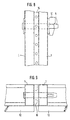
- the first figure 1 shows a base frame 1 with a subsequent base frame, formed in the illustrated embodiment from hollow metal profiles are.
- the frames are interlocked with push-through bolts connected, which are fixed on one side by means of an insert wedge.
- the frames 1 are with the help of in the illustrated embodiment on the lower corners attached tabs 2 and ceiling fittings 3 between the floor ceiling and floor fixed.
- the leveling on the floor is done using adjustable feet 4.
- the ceiling fittings 3, which are provided with grid holes, can the tabs 8 at the upper corners of the frame 1 to the respective ceiling height be adjusted.
- the tabs 8 also serve to attach Above the basic frame 1 to be arranged frame to increase.
- Surface branch profiles 6 can be arranged within the base frame 1 be positioned on the horizontal variation rails 7 and screwed are.
- the base frame 1 can be both in height and in the Width can be adjustable, preferably fixed base frame 1 with Grid are provided.
- the push-through bolts 9 with a round cross section are shown and turned head 9a, the slot 9b for receiving a Own wedge 10.
- the bolts 9 are also with a truncated cone provided that the insertion into corresponding holes on the base frame 1 facilitated.
- the bolts 9 are not only used for the connection the base frame 1 but also allow exact positioning the frame 1 to each other and also pass through the grid rails 16, 17, not shown. Finally, in FIGS 11 for the backing of the connecting elements 9 and 10.
- 4 and 5 are ways to cover the wall surfaces of the Base frame 1 shown. Different wall surface elements can be seen here 12, which are plasterboard, wood panels, metal panels, Glass plates or the like can act and the appropriate fasteners 13 can be fixed to the base frame 1.
- FIG. 6 and 7 each show a view from below and a side view the floor mounting the base frame 1.
- the floor mounting tabs are 2 welded to the corners of the frame 1 and through with the help of holes 14 predetermined kinks can be deformed towards the bottom.
- the floor mounting bracket 2 is through holes 16 on the floor screwed.
- Fig. 6 are in the lower variation rails 7 of the base frame 1 oval openings 15 are provided, which facilitate the Screwing the bottom mounting tabs 2 serve as well as the implementation of electrical lines, which are guided through the hollow profiles of the base frame 1 become.
- 8 to 11 show the arrangement of grid rails for attachment of goods carriers or other shop fittings between the Base frame 1.
- the grid rail is fixed in a simple manner by correspondingly elongated bolts 9, which connect the base frame 1 are necessary anyway.
- 8 and 9 is a grid rail with threads shown, while FIGS. 10 and 11 show grid rails with slots.
- grid rails with special connections for fastening are also conceivable of corresponding presentation elements.
- the Attachment of wall surface elements 12 by the arrangement of grid rails 16, 17 not affected between the base frame 1.
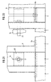
- the ceiling connector 3 consists of a flat steel with grid holes that connect allows for sheet metal tab with at least two screws.
- the flat steel of the ceiling connector 3 is immersed in the vertical profile of the base frame 1 one that is open at the top and bottom.
- At the top of the ceiling connector 3 is a flat steel flange at right angles to the flat steel with grid holes welded with 4 holes in this example. Through these holes the dowelling is carried out on a floor ceiling.
- FIG. 14 shows the ceiling connection according to FIGS. 12 and 13 again in side view. Furthermore, FIG. 14 shows the installation situation of a Partition according to the embodiment, both of which have already been mentioned Wall surface elements 12 and correspondingly suspended ceiling elements are shown.
- the pivot connection element 20 two about an axis to each other includes pivotable parts 20a and 20b, which are provided with push-through bolts 9 are.
- the joint is delimited towards the bolt 9 with a support flange. After wedging the frames 1 to be connected, they can be placed in the desired position Angles.
- the joints are fixed at the axis point with through screws, which also serve as an axis.
- FIG. 16 shows a rigid corner connector 21 with a square profile.
- the profile is lined with bolt connection openings on all its sides 21a. These openings are oval and can only be equipped from the outside. A separate bolt 23 is therefore necessary.
- the head of the bolt 23 is oval in shape and is preferably 90 ° after insertion turned to the right.
- One mounted in front of the head end of the bolt 23 Collet prevents unintentional insertion after the rotation Profile center when attaching the subsequent base frame 1.
- the padded Oval bolt connection openings 21a are cut out at the front to allow a radial movement of the adapter sleeve and this after 90 ° rotation to end.
- FIG. 17 shows a section of a within the frame width of the Base frame 1 freely placeable profile 6, which by clamping between the upper and lower variation rails 7 of the base frame 1 is fixed.
- the ones already described in FIG. 16 and here are also clearly visible existing bolt openings 21a.
- FIG. 20 shows the intersection profile 6 according to FIG. 17 again the installation situation is shown here. You can see one within the profile 6 arranged square profile 22 which is essentially the inclusion the bolt 23 is used. A foot 6a can also be seen, which is connected to the Profiles 6 is connected and the fixation, preferably the screw, serves on the base frame 1.
- 21 and 22 are essentially the elements of those already described 17 to 20 can be seen, but here in two different sectional views.
- FIG. 23 shows a branch at the end of a base frame 1.
- the square corner connection profile 21 from FIG. 16 is used here.
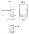
- the two-part leveling foot 4 consists of an insert shoe 41 and a set screw 4b.
- the insert shoe 4b, the base plate of the cross section corresponds to the vertical profiles of the base frame 1, points to the upper one A sheet of metal that is facing upwards on all sides. The sheet is used for positioning of foot 4 when inserting.
- the upstands on the narrow sides are profiled and bent to oversize. These spring back when inserted inside and prevent the resulting pressure from falling out Foot when setting up the base frame 1.
- the adjusting screw 4a is in one cylindrical threaded hole added, the set screw on one End has a round support plate for better weight distribution.
Landscapes
- Engineering & Computer Science (AREA)
- Architecture (AREA)
- Civil Engineering (AREA)
- Structural Engineering (AREA)
- Physics & Mathematics (AREA)
- Electromagnetism (AREA)
- Theoretical Computer Science (AREA)
- General Physics & Mathematics (AREA)
- Finishing Walls (AREA)
- Vending Machines For Individual Products (AREA)
- Furniture Connections (AREA)
- Supplying Of Containers To The Packaging Station (AREA)
- Ladders (AREA)
- Supports Or Holders For Household Use (AREA)
Claims (3)
- Système de cloison pour locaux professionnels et/ou commerciaux se composant d'éléments modulaires réutilisables, combinables, montables et démontables et pouvant supporter les charges d'éléments de présentation et/ou de décoration, le système de cloison comprenant une majorité de cadres de base (1) composés de profilés assemblés les uns aux autres et formant un quadrilatère, la surface du quadrilatère pouvant se remplir à l'aide d'éléments de surface de paroi (12) lesquels peuvent être fixés sur le cadre de base (1) et à chaque fois deux cadres de base (1) étant reliés latéralement sur leur face frontale dans l'état d'utilisation à l'aide de fermetures rapides (9), un rail d'enclenchement (16) pour la fixation de présentoirs de marchandises étant introduit entre les faces frontales latérales de deux cadres de base (1) juxtaposés, le rail d'enclenchement (16) étant traversé de part et d'autre du rail d'enclenchement (16) par les fermetures rapides (9) pour le raccordement des cadres de base (1).
- Le système de cloison selon la spécification 1 est caractérisé par le fait qu'un pied d'appui (4) modifiable en hauteur sur l'un des deux cadres de base (1) reliés l'un à l'autre est monté sur le plancher d'étage pour supporter le cadre de base (1) et qu'il y a une attache de fixation (2) pliée, en forme de z, qui est assemblée fixement avec sa première branche avec le profilé de cadre de base (1) s'étendant parallèlement au plancher d'étage, qui s'étend avec sa deuxième branche obliquement par rapport au plancher d'étage et se fixe de nouveau sur le plancher d'étage avec sa troisième branche s'étendant de nouveau parallèlement au plancher d'étage.
- Le système de cloison selon la spécification 2 est caractérisé par le fait que le profilé sur lequel est montée la première branche de l'attache de fixation (2) présente une ouverture (15) perpendiculaire au-dessus de la troisième branche de l'attache de fixation (2) pour faciliter un vissage de la troisième branche sur le plancher d'étage.
Applications Claiming Priority (3)
| Application Number | Priority Date | Filing Date | Title |
|---|---|---|---|
| DE29606690U | 1996-04-12 | ||
| DE29606690U DE29606690U1 (de) | 1996-04-12 | 1996-04-12 | Trennwandvorrichtung für Ladenlokale |
| PCT/EP1997/001791 WO1997039200A1 (fr) | 1996-04-12 | 1997-04-10 | Systeme de cloison de separation pour locaux commerciaux |
Publications (2)
| Publication Number | Publication Date |
|---|---|
| EP0891459A1 EP0891459A1 (fr) | 1999-01-20 |
| EP0891459B1 true EP0891459B1 (fr) | 2002-02-06 |
Family
ID=8022501
Family Applications (1)
| Application Number | Title | Priority Date | Filing Date |
|---|---|---|---|
| EP97919328A Expired - Lifetime EP0891459B1 (fr) | 1996-04-12 | 1997-04-10 | Systeme de cloison de separation pour locaux commerciaux |
Country Status (5)
| Country | Link |
|---|---|
| EP (1) | EP0891459B1 (fr) |
| JP (1) | JP2000508395A (fr) |
| AT (1) | ATE213043T1 (fr) |
| DE (2) | DE29606690U1 (fr) |
| WO (1) | WO1997039200A1 (fr) |
Cited By (1)
| Publication number | Priority date | Publication date | Assignee | Title |
|---|---|---|---|---|
| DE102009022479A1 (de) * | 2009-02-20 | 2010-09-02 | Isinger + Merz Gmbh | Mobiles modulares Wandsystem |
Families Citing this family (3)
| Publication number | Priority date | Publication date | Assignee | Title |
|---|---|---|---|---|
| DE29706156U1 (de) * | 1997-04-07 | 1998-08-06 | Preuss Messebaugesellschaft mbH, 25488 Holm | Bausatz für den Messe- und Ladenbau |
| DE29706850U1 (de) * | 1997-04-16 | 1998-11-12 | Deutscher Sparkassenverlag GmbH, 70565 Stuttgart | Präsentationssystem |
| EP2434068A3 (fr) * | 2010-09-24 | 2013-01-23 | Principle Holdings Limited | Système de mur modulaire |
Family Cites Families (8)
| Publication number | Priority date | Publication date | Assignee | Title |
|---|---|---|---|---|
| US4100709A (en) * | 1976-09-30 | 1978-07-18 | Harter Corporation | Frame construction for a divider wall |
| DE2848929A1 (de) * | 1978-11-08 | 1980-05-22 | Wb Handelsgesellschaft Fuer Be | Zu einer beliebigen gesamtheit zusammenfuegbare bauelementegruppe |
| FR2556422B3 (fr) * | 1983-12-08 | 1986-04-04 | Veys Bernard | Systeme d'assemblage d'elements notamment de panneaux composites et constructions mettant en oeuvre un tel systeme |
| US4625477A (en) * | 1985-12-13 | 1986-12-02 | Masonite Corporation | Display wall formed of readily attachable and detachable panels |
| DE3628672A1 (de) * | 1986-08-23 | 1988-02-25 | Dorn Uwe Gmbh | Mobiles plattenelement mit integrierter elektrischer stromverteilerschiene |
| US5187908A (en) * | 1990-10-22 | 1993-02-23 | La-Z-Boy Chair Company | Modular wall panel interconnection apparatus and method |
| DE4038958A1 (de) * | 1990-12-06 | 1992-06-11 | Feldkoetter Ingo H | Ladenbausystem |
| US5277005A (en) * | 1992-05-04 | 1994-01-11 | Teknion Furniture Systems | Free-standing partitioning panel |
-
1996
- 1996-04-12 DE DE29606690U patent/DE29606690U1/de not_active Expired - Lifetime
-
1997
- 1997-04-10 DE DE59706312T patent/DE59706312D1/de not_active Expired - Fee Related
- 1997-04-10 AT AT97919328T patent/ATE213043T1/de not_active IP Right Cessation
- 1997-04-10 EP EP97919328A patent/EP0891459B1/fr not_active Expired - Lifetime
- 1997-04-10 JP JP9536723A patent/JP2000508395A/ja active Pending
- 1997-04-10 WO PCT/EP1997/001791 patent/WO1997039200A1/fr not_active Ceased
Cited By (2)
| Publication number | Priority date | Publication date | Assignee | Title |
|---|---|---|---|---|
| DE102009022479A1 (de) * | 2009-02-20 | 2010-09-02 | Isinger + Merz Gmbh | Mobiles modulares Wandsystem |
| DE102009022479B4 (de) | 2009-02-20 | 2022-05-19 | Isinger + Merz Gmbh | Mobiles modulares Wandsystem |
Also Published As
| Publication number | Publication date |
|---|---|
| JP2000508395A (ja) | 2000-07-04 |
| DE29606690U1 (de) | 1996-08-01 |
| WO1997039200A1 (fr) | 1997-10-23 |
| ATE213043T1 (de) | 2002-02-15 |
| EP0891459A1 (fr) | 1999-01-20 |
| DE59706312D1 (de) | 2002-03-21 |
Similar Documents
| Publication | Publication Date | Title |
|---|---|---|
| DE69316247T2 (de) | Arbeitsraumtrennwandsystem | |
| DE69923950T2 (de) | Deckenträger und verfahren unter dessen verwendung | |
| EP0116261B1 (fr) | Jeu de pièces pour la construction d'un bâti pour le montage d'appareils et son utilisation | |
| DE9419429U1 (de) | Stellwand insbesondere für Messebauten | |
| EP0891459B1 (fr) | Systeme de cloison de separation pour locaux commerciaux | |
| EP2031145A2 (fr) | Plafond intérieur suspendu | |
| DE19502648C1 (de) | Tragvorrichtung für ein Podest für mehrgeschossig angeordnete Baustellencontainer | |
| EP3070215B1 (fr) | Module de revetement mural | |
| DE9410031U1 (de) | Unterdecke für Gebäuderäume | |
| DE1294639B (de) | Unterdecke aus an der Rohdecke aufgehaengten Tafeln | |
| DE3738766C2 (de) | Briefkastenanlage mit Fußgestell | |
| WO1993016246A1 (fr) | Dispositif pour insonoriser des pieces | |
| CH686966A5 (de) | Universell verwendbare Trenn- bzw. Ausstellungs- oder Praesentationswand. | |
| DE20315878U1 (de) | Adapter für eine Halterung zur Befestigung hinterlüfteter Fassadenelemente | |
| DE7924725U1 (de) | Stuetz- und traggeruest fuer eine aus einzelnen rasterelementen zusammensetzbare schallschutzverkleidung fuer maschinen, insbesondere schallschutzkapselung und -kabine | |
| CH635890A5 (en) | Partition-wall structure for forming boarded-off areas, principally for separating off cellars | |
| DE10235918B4 (de) | Montagesystem für Möbel und Verfahren zur Montage von Möbeln | |
| DE29708533U1 (de) | Zerlegbare Raumzelle | |
| AT352356B (de) | Variable raumbegrenzung | |
| DE19615447A1 (de) | Wandsystem insbesondere für Messestände | |
| DE2742504A1 (de) | Decken- und wandelemente umfassende variable raumbegrenzung | |
| DE2331976C2 (de) | Trennwand | |
| CH569163A5 (fr) | ||
| EP1366691A1 (fr) | Système de meuble de cuisine | |
| DE3418183A1 (de) | Verbindungselemente fuer kojenwaende |
Legal Events
| Date | Code | Title | Description |
|---|---|---|---|
| PUAI | Public reference made under article 153(3) epc to a published international application that has entered the european phase |
Free format text: ORIGINAL CODE: 0009012 |
|
| 17P | Request for examination filed |
Effective date: 19981110 |
|
| AK | Designated contracting states |
Kind code of ref document: A1 Designated state(s): AT BE CH DE DK ES FI FR GB GR IE IT LI LU NL PT SE |
|
| 17Q | First examination report despatched |
Effective date: 19990210 |
|
| GRAG | Despatch of communication of intention to grant |
Free format text: ORIGINAL CODE: EPIDOS AGRA |
|
| GRAG | Despatch of communication of intention to grant |
Free format text: ORIGINAL CODE: EPIDOS AGRA |
|
| GRAH | Despatch of communication of intention to grant a patent |
Free format text: ORIGINAL CODE: EPIDOS IGRA |
|
| GRAH | Despatch of communication of intention to grant a patent |
Free format text: ORIGINAL CODE: EPIDOS IGRA |
|
| GRAA | (expected) grant |
Free format text: ORIGINAL CODE: 0009210 |
|
| REG | Reference to a national code |
Ref country code: GB Ref legal event code: IF02 |
|
| AK | Designated contracting states |
Kind code of ref document: B1 Designated state(s): AT BE CH DE DK ES FI FR GB GR IE IT LI LU NL PT SE |
|
| PG25 | Lapsed in a contracting state [announced via postgrant information from national office to epo] |
Ref country code: NL Free format text: LAPSE BECAUSE OF FAILURE TO SUBMIT A TRANSLATION OF THE DESCRIPTION OR TO PAY THE FEE WITHIN THE PRESCRIBED TIME-LIMIT Effective date: 20020206 Ref country code: IT Free format text: LAPSE BECAUSE OF FAILURE TO SUBMIT A TRANSLATION OF THE DESCRIPTION OR TO PAY THE FEE WITHIN THE PRESCRIBED TIME-LIMIT;WARNING: LAPSES OF ITALIAN PATENTS WITH EFFECTIVE DATE BEFORE 2007 MAY HAVE OCCURRED AT ANY TIME BEFORE 2007. THE CORRECT EFFECTIVE DATE MAY BE DIFFERENT FROM THE ONE RECORDED. Effective date: 20020206 Ref country code: IE Free format text: LAPSE BECAUSE OF FAILURE TO SUBMIT A TRANSLATION OF THE DESCRIPTION OR TO PAY THE FEE WITHIN THE PRESCRIBED TIME-LIMIT Effective date: 20020206 Ref country code: GR Free format text: LAPSE BECAUSE OF FAILURE TO SUBMIT A TRANSLATION OF THE DESCRIPTION OR TO PAY THE FEE WITHIN THE PRESCRIBED TIME-LIMIT Effective date: 20020206 Ref country code: GB Free format text: LAPSE BECAUSE OF FAILURE TO SUBMIT A TRANSLATION OF THE DESCRIPTION OR TO PAY THE FEE WITHIN THE PRESCRIBED TIME-LIMIT Effective date: 20020206 Ref country code: FR Free format text: LAPSE BECAUSE OF FAILURE TO SUBMIT A TRANSLATION OF THE DESCRIPTION OR TO PAY THE FEE WITHIN THE PRESCRIBED TIME-LIMIT Effective date: 20020206 Ref country code: FI Free format text: LAPSE BECAUSE OF FAILURE TO SUBMIT A TRANSLATION OF THE DESCRIPTION OR TO PAY THE FEE WITHIN THE PRESCRIBED TIME-LIMIT Effective date: 20020206 |
|
| REF | Corresponds to: |
Ref document number: 213043 Country of ref document: AT Date of ref document: 20020215 Kind code of ref document: T |
|
| REG | Reference to a national code |
Ref country code: CH Ref legal event code: EP |
|
| REF | Corresponds to: |
Ref document number: 59706312 Country of ref document: DE Date of ref document: 20020321 |
|
| PG25 | Lapsed in a contracting state [announced via postgrant information from national office to epo] |
Ref country code: LU Free format text: LAPSE BECAUSE OF NON-PAYMENT OF DUE FEES Effective date: 20020410 |
|
| PG25 | Lapsed in a contracting state [announced via postgrant information from national office to epo] |
Ref country code: LI Free format text: LAPSE BECAUSE OF NON-PAYMENT OF DUE FEES Effective date: 20020430 Ref country code: CH Free format text: LAPSE BECAUSE OF NON-PAYMENT OF DUE FEES Effective date: 20020430 Ref country code: BE Free format text: LAPSE BECAUSE OF NON-PAYMENT OF DUE FEES Effective date: 20020430 |
|
| PG25 | Lapsed in a contracting state [announced via postgrant information from national office to epo] |
Ref country code: SE Free format text: LAPSE BECAUSE OF FAILURE TO SUBMIT A TRANSLATION OF THE DESCRIPTION OR TO PAY THE FEE WITHIN THE PRESCRIBED TIME-LIMIT Effective date: 20020506 Ref country code: PT Free format text: LAPSE BECAUSE OF FAILURE TO SUBMIT A TRANSLATION OF THE DESCRIPTION OR TO PAY THE FEE WITHIN THE PRESCRIBED TIME-LIMIT Effective date: 20020506 Ref country code: DK Free format text: LAPSE BECAUSE OF FAILURE TO SUBMIT A TRANSLATION OF THE DESCRIPTION OR TO PAY THE FEE WITHIN THE PRESCRIBED TIME-LIMIT Effective date: 20020506 |
|
| NLV1 | Nl: lapsed or annulled due to failure to fulfill the requirements of art. 29p and 29m of the patents act | ||
| GBV | Gb: ep patent (uk) treated as always having been void in accordance with gb section 77(7)/1977 [no translation filed] |
Effective date: 20020206 |
|
| PG25 | Lapsed in a contracting state [announced via postgrant information from national office to epo] |
Ref country code: ES Free format text: LAPSE BECAUSE OF FAILURE TO SUBMIT A TRANSLATION OF THE DESCRIPTION OR TO PAY THE FEE WITHIN THE PRESCRIBED TIME-LIMIT Effective date: 20020829 |
|
| REG | Reference to a national code |
Ref country code: IE Ref legal event code: FD4D |
|
| PGFP | Annual fee paid to national office [announced via postgrant information from national office to epo] |
Ref country code: AT Payment date: 20021028 Year of fee payment: 6 |
|
| EN | Fr: translation not filed | ||
| PLBE | No opposition filed within time limit |
Free format text: ORIGINAL CODE: 0009261 |
|
| REG | Reference to a national code |
Ref country code: CH Ref legal event code: PL |
|
| STAA | Information on the status of an ep patent application or granted ep patent |
Free format text: STATUS: NO OPPOSITION FILED WITHIN TIME LIMIT |
|
| 26N | No opposition filed |
Effective date: 20021107 |
|
| PG25 | Lapsed in a contracting state [announced via postgrant information from national office to epo] |
Ref country code: AT Free format text: LAPSE BECAUSE OF NON-PAYMENT OF DUE FEES Effective date: 20030410 |
|
| PGFP | Annual fee paid to national office [announced via postgrant information from national office to epo] |
Ref country code: DE Payment date: 20070205 Year of fee payment: 11 |
|
| PG25 | Lapsed in a contracting state [announced via postgrant information from national office to epo] |
Ref country code: DE Free format text: LAPSE BECAUSE OF NON-PAYMENT OF DUE FEES Effective date: 20081101 |