EP0891482B1 - Unite de turbine a gaz - Google Patents
Unite de turbine a gaz Download PDFInfo
- Publication number
- EP0891482B1 EP0891482B1 EP97918101A EP97918101A EP0891482B1 EP 0891482 B1 EP0891482 B1 EP 0891482B1 EP 97918101 A EP97918101 A EP 97918101A EP 97918101 A EP97918101 A EP 97918101A EP 0891482 B1 EP0891482 B1 EP 0891482B1
- Authority
- EP
- European Patent Office
- Prior art keywords
- gas turbine
- unit according
- turbine unit
- compressor
- turbine
- Prior art date
- Legal status (The legal status is an assumption and is not a legal conclusion. Google has not performed a legal analysis and makes no representation as to the accuracy of the status listed.)
- Expired - Lifetime
Links
- 238000001816 cooling Methods 0.000 claims abstract description 56
- 239000007789 gas Substances 0.000 claims description 120
- 239000007858 starting material Substances 0.000 claims description 17
- 239000000446 fuel Substances 0.000 claims description 12
- 238000004378 air conditioning Methods 0.000 claims description 6
- XLYOFNOQVPJJNP-UHFFFAOYSA-N water Substances O XLYOFNOQVPJJNP-UHFFFAOYSA-N 0.000 claims description 5
- 239000000112 cooling gas Substances 0.000 claims description 3
- 239000004519 grease Substances 0.000 claims description 3
- 230000008961 swelling Effects 0.000 claims 1
- 238000013461 design Methods 0.000 abstract description 5
- 239000003921 oil Substances 0.000 description 23
- 238000002485 combustion reaction Methods 0.000 description 18
- 230000009467 reduction Effects 0.000 description 14
- 238000010276 construction Methods 0.000 description 13
- 230000001143 conditioned effect Effects 0.000 description 9
- 238000004519 manufacturing process Methods 0.000 description 7
- VNWKTOKETHGBQD-UHFFFAOYSA-N methane Chemical compound C VNWKTOKETHGBQD-UHFFFAOYSA-N 0.000 description 6
- 230000008901 benefit Effects 0.000 description 5
- 230000005540 biological transmission Effects 0.000 description 5
- 230000005611 electricity Effects 0.000 description 4
- 238000007689 inspection Methods 0.000 description 4
- 238000012423 maintenance Methods 0.000 description 4
- 239000000463 material Substances 0.000 description 4
- 238000003860 storage Methods 0.000 description 4
- 238000012546 transfer Methods 0.000 description 4
- 239000011324 bead Substances 0.000 description 3
- 230000003750 conditioning effect Effects 0.000 description 3
- 238000005461 lubrication Methods 0.000 description 3
- 229920000049 Carbon (fiber) Polymers 0.000 description 2
- LFQSCWFLJHTTHZ-UHFFFAOYSA-N Ethanol Chemical compound CCO LFQSCWFLJHTTHZ-UHFFFAOYSA-N 0.000 description 2
- UFHFLCQGNIYNRP-UHFFFAOYSA-N Hydrogen Chemical compound [H][H] UFHFLCQGNIYNRP-UHFFFAOYSA-N 0.000 description 2
- 230000000712 assembly Effects 0.000 description 2
- 238000000429 assembly Methods 0.000 description 2
- 230000015572 biosynthetic process Effects 0.000 description 2
- 239000004917 carbon fiber Substances 0.000 description 2
- 239000000919 ceramic Substances 0.000 description 2
- 229910010293 ceramic material Inorganic materials 0.000 description 2
- 239000000567 combustion gas Substances 0.000 description 2
- 230000006835 compression Effects 0.000 description 2
- 238000007906 compression Methods 0.000 description 2
- 239000003651 drinking water Substances 0.000 description 2
- 235000020188 drinking water Nutrition 0.000 description 2
- 239000003502 gasoline Substances 0.000 description 2
- 238000010438 heat treatment Methods 0.000 description 2
- 229910052739 hydrogen Inorganic materials 0.000 description 2
- 239000001257 hydrogen Substances 0.000 description 2
- 230000006872 improvement Effects 0.000 description 2
- 238000009434 installation Methods 0.000 description 2
- 239000007788 liquid Substances 0.000 description 2
- 239000000203 mixture Substances 0.000 description 2
- 239000003345 natural gas Substances 0.000 description 2
- 238000013021 overheating Methods 0.000 description 2
- 238000011144 upstream manufacturing Methods 0.000 description 2
- 238000004804 winding Methods 0.000 description 2
- -1 biogas Chemical compound 0.000 description 1
- 210000000988 bone and bone Anatomy 0.000 description 1
- 238000005266 casting Methods 0.000 description 1
- 230000015556 catabolic process Effects 0.000 description 1
- 230000008859 change Effects 0.000 description 1
- 239000000498 cooling water Substances 0.000 description 1
- 230000008878 coupling Effects 0.000 description 1
- 238000010168 coupling process Methods 0.000 description 1
- 238000005859 coupling reaction Methods 0.000 description 1
- 239000002283 diesel fuel Substances 0.000 description 1
- 239000004744 fabric Substances 0.000 description 1
- 230000002349 favourable effect Effects 0.000 description 1
- 238000007667 floating Methods 0.000 description 1
- 238000000034 method Methods 0.000 description 1
- 238000010248 power generation Methods 0.000 description 1
- 230000002265 prevention Effects 0.000 description 1
- 230000008569 process Effects 0.000 description 1
- 230000002040 relaxant effect Effects 0.000 description 1
- 230000008439 repair process Effects 0.000 description 1
- 230000003319 supportive effect Effects 0.000 description 1
- 210000004243 sweat Anatomy 0.000 description 1
- 238000012549 training Methods 0.000 description 1
Images


Classifications
-
- F—MECHANICAL ENGINEERING; LIGHTING; HEATING; WEAPONS; BLASTING
- F02—COMBUSTION ENGINES; HOT-GAS OR COMBUSTION-PRODUCT ENGINE PLANTS
- F02C—GAS-TURBINE PLANTS; AIR INTAKES FOR JET-PROPULSION PLANTS; CONTROLLING FUEL SUPPLY IN AIR-BREATHING JET-PROPULSION PLANTS
- F02C3/00—Gas-turbine plants characterised by the use of combustion products as the working fluid
- F02C3/04—Gas-turbine plants characterised by the use of combustion products as the working fluid having a turbine driving a compressor
- F02C3/045—Gas-turbine plants characterised by the use of combustion products as the working fluid having a turbine driving a compressor having compressor and turbine passages in a single rotor-module
- F02C3/05—Gas-turbine plants characterised by the use of combustion products as the working fluid having a turbine driving a compressor having compressor and turbine passages in a single rotor-module the compressor and the turbine being of the radial flow type
-
- F—MECHANICAL ENGINEERING; LIGHTING; HEATING; WEAPONS; BLASTING
- F01—MACHINES OR ENGINES IN GENERAL; ENGINE PLANTS IN GENERAL; STEAM ENGINES
- F01D—NON-POSITIVE DISPLACEMENT MACHINES OR ENGINES, e.g. STEAM TURBINES
- F01D15/00—Adaptations of machines or engines for special use; Combinations of engines with devices driven thereby
- F01D15/10—Adaptations for driving, or combinations with, electric generators
-
- F—MECHANICAL ENGINEERING; LIGHTING; HEATING; WEAPONS; BLASTING
- F01—MACHINES OR ENGINES IN GENERAL; ENGINE PLANTS IN GENERAL; STEAM ENGINES
- F01D—NON-POSITIVE DISPLACEMENT MACHINES OR ENGINES, e.g. STEAM TURBINES
- F01D15/00—Adaptations of machines or engines for special use; Combinations of engines with devices driven thereby
- F01D15/12—Combinations with mechanical gearing
-
- F—MECHANICAL ENGINEERING; LIGHTING; HEATING; WEAPONS; BLASTING
- F01—MACHINES OR ENGINES IN GENERAL; ENGINE PLANTS IN GENERAL; STEAM ENGINES
- F01D—NON-POSITIVE DISPLACEMENT MACHINES OR ENGINES, e.g. STEAM TURBINES
- F01D9/00—Stators
- F01D9/02—Nozzles; Nozzle boxes; Stator blades; Guide conduits, e.g. individual nozzles
- F01D9/04—Nozzles; Nozzle boxes; Stator blades; Guide conduits, e.g. individual nozzles forming ring or sector
- F01D9/045—Nozzles; Nozzle boxes; Stator blades; Guide conduits, e.g. individual nozzles forming ring or sector for radial flow machines or engines
-
- F—MECHANICAL ENGINEERING; LIGHTING; HEATING; WEAPONS; BLASTING
- F05—INDEXING SCHEMES RELATING TO ENGINES OR PUMPS IN VARIOUS SUBCLASSES OF CLASSES F01-F04
- F05D—INDEXING SCHEME FOR ASPECTS RELATING TO NON-POSITIVE-DISPLACEMENT MACHINES OR ENGINES, GAS-TURBINES OR JET-PROPULSION PLANTS
- F05D2220/00—Application
- F05D2220/70—Application in combination with
- F05D2220/76—Application in combination with an electrical generator
-
- Y—GENERAL TAGGING OF NEW TECHNOLOGICAL DEVELOPMENTS; GENERAL TAGGING OF CROSS-SECTIONAL TECHNOLOGIES SPANNING OVER SEVERAL SECTIONS OF THE IPC; TECHNICAL SUBJECTS COVERED BY FORMER USPC CROSS-REFERENCE ART COLLECTIONS [XRACs] AND DIGESTS
- Y02—TECHNOLOGIES OR APPLICATIONS FOR MITIGATION OR ADAPTATION AGAINST CLIMATE CHANGE
- Y02T—CLIMATE CHANGE MITIGATION TECHNOLOGIES RELATED TO TRANSPORTATION
- Y02T50/00—Aeronautics or air transport
- Y02T50/60—Efficient propulsion technologies, e.g. for aircraft
Definitions
- the invention relates to a gas turbine unit according to the preamble of Claim 1.
- Gas turbines are often used to drive electrical generators when the Construction effort should be kept low or there is a lack of cooling water.
- From GB-A-838 332 is a gas turbine unit with one supported by two bearings Shaft and known with a compressor, in which the rotor of the compressor and a Turbine impeller are arranged side by side on the same shaft. Besides, one is second turbine mounted on a second shaft.
- the invention lies u. a, based on the problem, a compact, single-shaft gas turbine to develop the modular, quick and easy on different machines can be coupled. Arrangements for air conditioning are also said to be simple and inexpensive construction can be made available.
- the compressor rotor and the turbine rotor can be arranged at a short distance from each other since the plate / guide vane ring is a compact design favors. This allows a significant reduction in Reach turbine weight.
- the turbine rotor and the compressor rotor integrally formed. The manufacturing effort can be significantly Reduce.
- openings in the turbine guide vanes for the escape of Cooling air are preferably provided. These openings are expediently at the thermal arranged particularly stressed areas of the turbine guide vanes. As a result, a Film cooling and / or perspiration cooling of the stator blades can be achieved.
- the plate between the diffuser vanes and Turbine guide vanes formed in one piece with the diffuser and turbine guide vanes is. With this arrangement, the turbine guide vanes become effective against overheating protected. At the same time, heat is added to the compressed air, causing simple way the efficiency of the gas turbine is increased.
- the plate with the Diffuser and turbine guide vanes preferably consist of a ceramic Material.
- the turbine rotor is one surrounded by a double-walled housing, in the interstices of which cooling gas from the turbine guide vanes is directed.
- the double-walled housing prevents heat transfer directly from the combustion chamber to the nozzle or turbine wheel and acts as a heat shield.
- nozzle-shaped are in the outer wall of the double-walled housing Air outlet openings provided.
- the cooling gas emerges from the openings, causing cooling of the outer housing wall is achieved.
- the cooling air flow is fully fed into the combustion chamber and heats up continuously on the way to Combustion chamber, which in turn leads to an overall improvement in efficiency.
- the compressor housing, the plate with the Diffuser blades, which are turbine guide vanes and the double-walled housing preferably clamped together, which makes installation quick and easy is possible.
- the storage being provided on the compressor side is.
- the storage is outside the high temperature zones, i.e. on the driven side. This means that the bearings are simpler can be, since, for example, no complex cooling is necessary.
- cooling channels are in the one-piece rotor provided between the compressor side and the turbine blades.
- the channels in the turbine blades have openings that lead to the double-walled housing are aligned.
- the Gas turbine surrounding housing a bead for attachment to an end Plate, the plate with the diffuser and turbine guide vanes and the double-walled Housing carries, provided by means of a V-profile strap.
- a V-profile strap is commercial, e.g. from Smith & Johnson (Keighley) Ltd.
- the turbine housing can be removed in a very short time are cleared, whereby the view of the turbine parts arranged inside is released. This simplifies maintenance and inspection.
- the shaft is preferably connected to a reduction gear.
- a reduction gear In particular, a planetary gear is provided, the sun gear with the rotor of the turbine is arranged on a common shaft. With this configuration bearings can be saved, i.e. the rotor and the gear come with two bearing locations each.
- Axial forces emanating from the turbine rotor are preferably caused by helical teeth the gear wheels compensated, or on the bearing of the bell wheel transfer.
- these are on the output shaft Pump wheel of an oil pump, the pump wheel of a fuel delivery pump and a rotor a starter motor arranged.
- the Starter motor can be a DC or three-phase motor.
- the cooling fan can electrical parts of the gas turbine and the gear housing by a corresponding Air flow, e.g. through cooling fins, cool or flow through a cooler. On additional oil cooler is therefore not necessary. You can also save heavy housing for a fuel pump, for an oil pump, for a starter, one Generator and a cooling fan. There are only two bearings for all these assemblies, namely those of the output shaft required.
- the construction according to the invention makes it possible to provide a drive unit which e.g. at a power of 150 KW only a weight of approx. 20 kg and uses less fuel and therefore a higher one Has efficiency.
- the maintenance and inspection intervals are reduced and increased reliability.
- the turbine package / module according to the invention to which the reduction gear and Auxiliary units are so handy and light that they can be connected using e.g. Stud bolts between the turbine and the optionally interchangeable various exchangeable ones driven units can be dispensed with.
- the gear neck with a collar which is used by means of a quick-disconnect coupling, preferably V-clamp, the turbine package / module in a few seconds with various units such as pumps, generators, vehicles, helicopters, Motor boats to connect or separate construction machinery.
- a quick-disconnect coupling preferably V-clamp
- the same unit can e.g. only as a drive unit in a vehicle (Jeep) and afterwards e.g. can be used as a drive for a fire pump etc.
- the unit with the gas turbine on the V-profile strap Generator housing attached For electrical energy e.g. for the aircraft on-board power supply of 400 Hz generate, the unit with the gas turbine on the V-profile strap Generator housing attached.
- the unit according to the invention described above can be equipped with an electric motor, electric generator or with a motor-generator unit (diesel engine / electric motor or also petrol engine) can be coupled.
- a motor-generator unit diesel engine / electric motor or also petrol engine
- a unit according to the invention which is coupled to a motor / generator is in particular provided with the following facilities:
- Integrated cooling, integrated voltage regulation, integrated overload protection, integrated Power switch contacts such as 3-phase relay, integrated instrumentation, which can optionally be removed and also using a connecting cable as a remote control is used, integrated under / over voltage, integrated under / over frequency.
- the power supply units are equipped with handles for easy attachment and removal. Aids such as a crane, forklift, etc. are not required.
- the weight of a 90 KVA, 400 Hz Energy packages for airplanes etc. are only approx. 55 kg.
- a gas turbine unit of the type described above is also advantageously connected to one Transfer case with at least two output shafts using Quick Disconnect flange connections coupled.
- the gas turbine unit according to the invention can be used in conjunction with hydraulic systems and power supplies for helicopters.
- the gas turbine unit according to the invention can also be advantageously used with a turbo compressor connect with which take-off air is to be generated for aircraft. Also for The gas turbine unit according to the invention is suitable for driving high-pressure compressors, to drive pneumatic tools, chassis cylinders with compressed air fill up and fill pressure accumulator and compressed air bottles.
- the gas turbine unit according to the invention is particularly good for driving pumps, e.g. suitable for the fire brigade or for drinking water supply.
- the gas turbine unit according to the invention can also be a turbo compressor for drive the generation of conditioned air as well as an electric generator.
- the gas turbine unit according to the invention is also particularly suitable for driving Water jet pumps for boat drives and pumps for sucking up oil spills in tanker accidents.
- the heat in the exhaust gas stream, in which the exhaust gases are at least, is also used partially passed through a heat exchanger, so that the gas turbine unit both for the generation of mechanical energy and for hot water supply can be used.
- the gas turbine unit can also drive electrical generators for power generation with 50/60 Hz can be used.
- the invention is Gas turbine unit is also well suited as a drive for an aircraft propeller.
- the Gas turbine unit is here with a reduction gear and a propeller, e.g. a jacket screw.
- the complete unit consists of a gas turbine unit with auxiliary units and a reduction gear and propellers. This complete aggregate is especially with the cell connected to an aircraft.
- the connecting element is the one described above Quick-Disconnect connection (V-profile clamping element) provided. Because of a such a connection, an engine change can be carried out quickly.
- a complete unit consisting of a gas turbine unit with auxiliary units is transformed and reduction gear designed for installation in a helicopter.
- a unit consisting of a gas turbine unit with auxiliary units is preferably equipped with a continuously variable transmission, e.g. according to the PIV or van Dornen principle, for land vehicles used.
- the unit is used in particular in trucks even where large or changing torques occur frequently, such as with tractors. Construction machinery, aircraft tugs.
- a gas turbine unit is on the side facing away from the turbine rotor with an axial or a radial turbine wheel a turbine connected to the via a heat exchanger and a regulator Compressor of the gas turbine is connected.
- This embodiment delivers continuously and pulsation-free oil and germ-free, hot or cold air.
- the electrical Generator driven by the shaft of the turbine unit also delivers the unit Electricity.
- the unit manages with two bearings. The branched off from the compressor Air is heated or cooled in the heat exchanger and through appropriate control measures converted into conditioned air. Diesel oil, Gasoline, natural gas, biogas, alcohol or hydrogen or mixtures of these Fabrics are used.
- the gas turbine unit is included a further turbine arranged on the shaft, the compressed air is supplied to the atmosphere.
- the compressor stage of the other turbine generates an air flow that is in the Turbine does work while relaxing.
- the embodiment has the advantage that without loss of performance on the drive side / turbine of the air to be sucked in Filters can be connected upstream and the air does not use the combustion gas Drive turbine comes into contact.
- the only two bearings of this unit can be provided with grease chambers or get oil lubrication because on the one hand the bearing points through the intake air or through targeted use conditioned air can be cooled and on the other hand no heat through mechanical losses can occur due to, for example, a lack of gear wheels.
- the starter or generator is used as a short-circuit motor or as a generator with a rotor Permanent magnets formed.
- the generator can operate the gas turbines feed electrical appliances.
- the starter battery can be charged.
- the turbine on the fresh gas side can also be designed as an axial stage.
- the gas turbine unit there is between the two bearing points the gas turbine unit the rotor of an electrical machine such as a generator arranged.
- the two bearing points of the machine and the generator are here at the same time the bearings of the gas turbine unit.
- the electrical energy generated is e.g. B. used in the operation of a cooling system.
- the invention also relates to an arrangement for conditioning air, the is characterized in that a compressor-turbine arrangement of over two Bearing supported shaft goes out, and that on the shaft at least one more Turbine is mounted, which is connected downstream of one or the compressor Heat exchanger compressed air can be supplied.
- the further turbine bleeds the compressor-turbine arrangement is feedable. or that the further turbine of the shaft compressed air can be fed to another compressor. Furthermore, one can on the shaft Rotor of a generator can be arranged.
- a particularly noteworthy inventive design relates to a Arrangement for conditioning air, which is characterized in that a Turbine-compressor arrangement is mounted on a shaft that compressed air of the Compressor can be fed to the turbine via a heat exchanger and that the shaft is connected to a further drivable shaft via a reduction gear.
- the reduction gear can be a between or outside of two bearings Shaft-mounted planetary gear, the second shaft of its bell wheel starts with which a pump and / or a fan can be connected, the second The shaft runs coaxially with the shaft.
- the further shaft via a diesel, Otto or electric motor or Gas turbine unit can be driven.
- turbo compressor unit which thereby whiskennzeichneet that the turbo compressor unit is mounted on a shaft
- Turbo compressor unit includes that between two or outside two bearings a reduction gear is mounted on the shaft, from which a further shaft extends, which can be driven by a drive unit.
- the reduction gear is a planetary gear, the bell wheel of which with the Drive unit connectable further shaft goes out, which in turn coaxial with the The shaft of the turbo compressor unit runs.
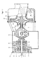
- Fig. 1 is a side view, partially in section, a bypass gas turbine unit, which includes a compressor impeller 10 and a turbine impeller 12.
- the compressor impeller 10 and the turbine impeller 12 are side by side on the same Shaft 14 arranged.
- the turbine impeller 12 and the compressor impeller 10 formed in one piece in the form of a turbine rotor.
- the compression impeller 10 has compressor blades 16 which axially air through an opening 18 in the Aspirate end wall 20 of a housing 22 and compress the air radially.
- the ring-shaped End wall 20 forms one side of the housing 22, which is still a hollow cylindrical Has housing section 24 which u.a. includes a combustion chamber 26.
- a bearing 27 of the shaft 14 is in a End wall of a housing 28 which is connected to the housing 22 and a planetary gear 30 contains as a reduction gear.
- the second bearing 32 of the shaft is located also in the housing 28.
- the planetary gears of the gearbox are not specified.
- a bell wheel is attached to the end of a shaft 34 which is in a pump block 36 is rotatably supported at two points, which are not described in detail.
- the pump block 36 contains an oil pump 38, the unspecified pump wheel of the Shaft 34 is driven.
- In the pump block 36 there is a filter in the course of the oil lines 40 arranged.
- a starter generator With the shaft 34 is still the rotor 44 of a starter generator is connected to which an air wheel 46 is also attached is.
- the starter 47 of the generator is attached to a flange 48, one of which Stub shaft 50, protrudes outward for the connection of power machines.
- the oil pump 38, the fuel pump 42, the air wheel 46 and the starter generator are in hereinafter also referred to as an auxiliary unit.
- Diffuser blades are located radially on the outside of the rotor blades 10 of the compressor 10 52, which supply the compressed air to a duct 53 which carries the air into the Combustion chamber conducts.
- the diffuser blades 52 jump from one side of a plate 54 before, from whose other side guide vanes 56 of the turbine. Plate 54 thus separates the compressor from the turbine part.
- the diffuser blades 52 include Cavities 58, which is shown in particular in FIGS. 3 to 7.
- the turbine blades, too 56 contain cooling channels or cavities 60.
- the flow pattern is for arrows 72 with a plate 72 with compressor guide vanes clearly marked. If the cross section next to the bolts 66 for 6, the openings 78 are present in the plate, those on the turbine side in the cooling channel or cavities 80 of the turbine guide vanes 84 open, causing air from the compressor side into the hollow Turbine guide vanes 84 arrives.
- a plate 86 is shown with diffuser vanes 88, not only on the Tips 90 slots for the air supply but also between their ends Interruption and offset of the guide vane walls facing the blades Have slots through which cooling air enters the hollow guide vanes. From the Cavities, the cooling air flows through the annular openings 92 between the Fastening bolts 94 in the cooling channels or cavities designated 96 in FIG. 7 of turbine guide vanes 98.
- the channel 53 has openings 100 through which cooling air from the channel into the combustion chamber 26 occurs so that the channel walls are also cooled on the combustion chamber side.
- the Wall 64 has passages for the bolts 66 which form an annular gap between the Leave bolts and the outer diameter of the openings free. Through this column cooling air flows into an inner double-walled housing, one wall 64 of which Nozzle forms.
- the second wall 102 forms a heat shield and delimits on its side the combustion chamber 26 or protects the wall 64.
- In this wall 102 are different Provide small nozzle-shaped openings 104 through which the Cooling air enters the combustion chamber 26 and the wall 102 also from the Combustion chamber side cools out. Over the openings 104 or a group of such Openings may have baffles 106 disposed in the combustion chamber. This Baffles 106 direct the cooling air along the wall 102, thereby cooling is reinforced.
- the plate 54 with the guide vanes can consist of ceramic.
- the design of the gas turbine described above enables the provision of a compact, self-sufficient, modular gas turbine unit, which with a variety of Operating materials - liquid or gaseous - can be operated.
- An autonomous modular system is made available, which has characteristics described below and with a variety of Operating materials - liquid or gaseous (biogas / environment) - can be operated.
- the airflow in the diffuser split in such a way that e.g. by means of nozzle-shaped openings in the diffuser from Compressor flowing gas through the opposite side of the Diffuser plate 54 located turbine stator blades 56 presses and thus an extreme Cooling of these blades takes place.
- this air is added locally used to pass some of this air to particularly critical hot zones of the stator blades to let out to film cooling and / or perspiration cooling of the stator blades create.
- the diffuser plate 54 supports the compressor guide vanes 52 and Turbine guide blades 56 serves and thus as a separator between the cold and hot parts acts, the turbine guide vanes 56 are also very effective by convection cooling protected against overheating. It also creates a very simple and inexpensive to manufacture and easily editable workpiece, which is even cheap and easy to manufacture in ceramics.
- the fresh gas cools - after it has flowed through the guide vanes - also the housing / nozzle, which surrounds the turbine wheel in which the heat shield 102 precedes the nozzle protects the direct exposure to the hot gas emerging from the combustion chamber.
- this heat shield 102 is already part of the combustion chamber represents and is forcibly cooled from one side, because of the guide vanes pressed fresh gas into the cavity by means of axial openings in the nozzle reached, which is present between the nozzle and the heat shield.
- In the area of Nozzle ends are small radial openings in the heat shield / combustion chamber.
- the cooling air flow is thus fed to the combustion chamber 26 in its entirety and is not lost. It heats up continuously on the way to the combustion chamber 26, which in turn results in an overall efficiency improvement.
- the Warmed axial openings in the nozzle are preferably placed so that they with the axial openings in the diffuser plate 54 and the compressor inlet housing lie on the same pitch circle. This results in the possibility of the entire package (Compressor inlet housing, diffuser plate 54, nozzle, heat shield 102) to each other tense.
- the compressor and turbine impeller 10, 12 made from a single workpiece (blank) and the bearing base of this rotor designed so that it is outside the Hot part is located, i.e. Towards drive side.
- the rotor is circumferentially between Compressor and turbine, i.e. between the radial outer edge of the rotor and the Diffuser plate 54 sealed like a labyrinth, so that only slight fresh gas losses towards the hot part are to be expected, but these act on the tips of the sheets there and in turn are useful for cooling.
- the rotor is designed so that the turbine blades are partially hollow or channels have and fresh gas from the compressor side through the blades of the turbine side can flow against the inner wall of the surrounding nozzle. Can too Openings can be provided which cover the turbine blades with a film and / or Provide perspiration cooling.
- the connection can, if necessary, e.g. during inspection and maintenance work be solved very quickly, so that the view of the compressor and turbine side Shovels is released.
- the downstream reduction gear ensures the desired torque (preferably planetary gears).
- the planet's sun gear is already on the Rotor shaft 14, so there is no need for additional bearings, i.e. Turbine rotor and Planet comes with a total of two bearings for the quick and therefore critical Area out.
- the unit In its further configuration, the unit also stands out from conventional ones known systems because e.g. no further gears and gears for accessories available.
- the starter is also located on the output shaft and generator or starter generator, which both as direct current and as AC / three-phase variant can be formed.
- the neck of the housing also contains the cooling fan, which is also connected to the output shaft is connected and not only cools the electrical part of the system, but also also the ribbed gear housing / oil due to the appropriately arranged air duct. An additional oil cooler can therefore be dispensed with. For extreme load cases this is downstream of the fan in terms of flow.
- heavy housings and devices can be used for fuel pump, oil pump, starter, generator, cooling fan and other accessories be dispensed with, i.e. only two bearings in total for all of these assemblies including the output shaft are necessary.
- the invention now makes it possible to provide a drive unit, which e.g. at a power of 150 KW only has a weight of approx. 20 kg, needs less fuel and therefore higher efficiency having.
- the maintenance and inspection intervals are reduced and the reliability increased.
- the turbine package / module is so handy and light that a connection by means of e.g. Stud bolts between the turbine and the optionally connected various replaceable units to be driven can be dispensed with.
- the flange 48 which the gear housing to the side of the machines to be connected or closes devices, has a collar 112 on its outer edge, which connects with a corresponding bundle of the device to be connected to Applying a V-profile strap is suitable.
- Such a quick disconnect connection allows the gas turbine unit to be connected and disconnected from machines such as pumps, generators, vehicles, helicopters, motor boats or construction machinery.
- the same unit can e.g. only as a drive system in a vehicle (Jeep) and afterwards e.g. can be used as a drive for a fire pump etc.
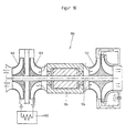
- Fig. 8 shows a gas turbine unit 114, which with respect to the compressor and Turbine stage has the structure shown in FIGS. 1 to 7, but on its turbine shaft 116, which has only two bearings 118, 120, the rotor 122 of an electrical Machine 124 carries.
- This machine 124 works as a generator, the electricity one electric motor 126 supplies, the rotor shaft 128 at their ends one each Compressor 130 and a turbine 132 carries.
- the compressor 130 compresses air that is fed to the turbine 132 via a heat exchanger 134, in which the air relaxed.
- the device according to Fig. 8 is used to produce conditioned air, e.g. Cooling air.
- FIG. 9 shows a gas turbine unit 136 with which in connection with FIGS. 1 to 7 described structure.
- the output shaft 138 can optionally with a Energy converter 140, a continuously variable transmission 142 or a transfer case with at least two output shafts 146, 148 are connected without one Restriction of the invention is intended to take place. Rather, use cases are purely exemplary demonstrated the teaching of the invention.
- the small gas turbine 150 includes a compressor turbine unit 152, as described above in connection with FIGS. 1 to 7 or a other known or conventional compressor turbine arrangement or one Arrangement in which the rotor with the compressor and turbine blades is not is formed in one piece.
- the rotor of an electrical machine 156 sits on the turbine shaft 154
- a compressor 158 and a turbine 160 are arranged at the second end of the rotor shaft 154.
- the air compressed by the compressor 158 is passed through a heat exchanger 162 passed and then gets into the turbine 160.
- the small gas turbine 150 generates pneumatic and electrical energy.
- a gas turbine unit 164 is provided with an electrical machine 166.
- On one end of the turbine shaft 168 is a turbine 170 with its Impeller stored on the fly.
- the turbine 170 is bleed air from the compressor stage Gas turbine supplied via a heat exchanger 172.
- 11 can be electrical energy and / or pneumatic energy or conditioned air for Generate cooling or heating.
- a hydraulic and power supply package can be used with the gas turbine unit according to the invention for the supply of various helicopters. Furthermore, the gas turbine unit according to the invention can be equipped with a turbo compressor form a turbo compressor package for the generation of starting air.
- Another application is the connection of the invention Gas turbine with a high pressure compressor for pneumatic tools, pressure filling of vehicle cylinders, pressure accumulators, compressed air bottles etc.
- gas turbine according to the invention can be an extinguishing pump for fire services or Drive the drinking water supply.
- the gas turbine unit according to the invention can be a water jet pump for boat drives and drive to extract oil spills in tanker accidents.
- the driven electrical machines are used for the electrical energy supply 50/60 Hz.
- the gas turbine according to the invention can also be used as an energy package for aircraft drives be used with a reduction gear and a propeller e.g. one Coat screw.
- the Drive unit consists of the turbine according to the invention with a quick disconnect connection (V-clamp).
- V-clamp quick disconnect connection
- the system is self-sufficient continuously variable transmission, e.g. provided according to the PIV or van Dornen principle.
- the Unit can also be used where there are large or changing torques common: aircraft tractors, tractors, construction machines.
- the gas turbines described above work continuously, pulsation-free and can oil and supply germ-free, hot or cold air and electricity. They can be operated with fuels such as diesel, petrol, natural gas, biogas, alcohol, hydrogen and Mixtures. These turbines only need two bearings. The axle and Radial forces can be largely compensated for.
- the turbine system exists on the one hand e.g. from a gas turbine of the type described above, the Turbine wheel can also be an axial stage.
- the rotor shaft opens on the Exit side not in a planetary gear, but carries at least one turbine wheel like Casing. This turbine wheel receives bleed air from the compressor side via a heat exchanger Drive turbine fed where it relaxed and by appropriate Control measures provide the desired conditioned air (Fig. 11). Such The arrangement is particularly noteworthy.
- FIG. 10 Another embodiment consists of a compressor wheel and a turbine wheel, both of which are also on the rotor shaft. Instead of the bleed air generated here separate compressor stage the air flow, which in the manner described on Turbine wheel does work and relaxes (Fig. 10).
- This variant has the advantage that A filter without loss of performance on the drive side / turbine of the air to be drawn in can be connected upstream and the air with the combustion gas Drive turbine comes into contact. The only two bearings of this unit can be provided with grease chambers or get oil lubrication.
- the starter of the system or the generator is located between the two bearing points.
- This motor / generator preferably consists of a squirrel-cage rotor or with permanent magnet-equipped rotor and a corresponding field winding.
- the turbine wheel on the fresh gas side can also be designed as an axial step. When using a compressor / turbine wheel there may be a small advantage from a single casting, which Supportive measures that are used to eliminate ice formation acts. Convection.
- the gas turbine shown in FIG. 8 drives a power generator without an intermediate gear on.
- the two storage locations of the generator are also the storage base of the turbine rotor - a shaft.
- the generated AC / three-phase voltage is used for the operation of a cooling system.
- FIG. 12 shows a turbocompressor unit 174 which is designed to be driven by diesel, Otto, electric motor or by the gas turbine unit described above is suitable.
- the turbocompressor unit 174 has a turbocompressor unit 176 which is floating on a shaft 178, the two unspecified bearings contains.
- a planetary gear 180 is arranged between the two bearings Bell wheel sits on a shaft 182 with which a pump 184 and a fan 186 connected is.
- the housing 188 in which the planetary gear 180, the pump 184 and the fan 186, has a collar or bead 190 for connection by means of a V-profile strap to the prime mover.
- the turbo compressor unit 174 can be used as an airport back-up system and as a universal device be used for technical support services. Furthermore, an insert in Vehicles, construction machines, helicopters and airplanes etc. possible.
- FIG. 13 shows something that is particularly noteworthy and thus unique Aggregate 192, which is intended for air conditioning tasks and by the same Machines can be driven like the turbocompressor unit shown in FIG. 12.
- a unit consisting of a compressor 194 and a turbine 196, which air-wise over one Heat exchangers 197 are connected to receive conditioned air, sits on one Shaft 198 or is overhung on it. With the shaft 198 is still a Planetary gear 200 connected, the bell wheel 202 at one end of a shaft 204. is arranged, which is intended for connection to the prime mover. With the A pump 208 and a fan 210 are connected to shaft 204 in housing 206.
- the invention makes a modular system available, the individual Contains aggregates / modules that e.g. for the generation of electricity, compressed air, air-conditioned Air are determined, the units / modules due to uniform connection elements are interchangeable.
- the addition or removal of modules does not require any expert fitters because of V-profile straps and uniform bead dimensions are provided on the module housing.
- the electrical machines used in the units described above or Generators are completely self-regulating / self-sufficient and contain everything related to protection and Control units are necessary.
- the control and operating panel for the machines is designed so that it can also be connected using a cable harness / extension cable with end plugs can be used for remote control. Handles at the top of the case, which surround the units and completely with the generator's own air cooling be flooded, make it easier to hold during assembly of the V-clamp and wearing.
- An Airstart module looks similar to the generator set.
- the Airstart unit is completely encapsulated, has only two bearings for the high-speed Part. There are no other shafts or gears apart from the planetary gear.
- the oil pump is integrated on the drive shaft, as is the cooling fan. Oil filters, Oil supply, oil cooler, oil pressure control are integrated in the housing.
- the pinion shaft of the The sun wheel also carries the compressor rotor in one or more stages. Sits a turbine wheel also on the extended common shaft, the module can be used as Air conditioning work as already mentioned.
- Devices or units of the type described above can be used in motor vehicles because the respective unit is independent of the main drive of the vehicle work and can also provide useful services in the event of breakdowns. This can be electrical and pneumatic energy are generated.
- the turbines described above are designed so that various parts made of ceramic materials and other parts are made of carbon fiber materials.
- the starter generators have a very high tightening / torque, which is already results from the large diameter of the rotor, so that the turbine in the shortest possible time Zero can be brought to operating speed. This is very important in vehicle construction and where the torque characteristic of the add-on module requires it.
- the fan can not only be used to cool the oil circuit.
- the teaching according to the invention is not limited to a specific internal one technical embodiment of a gas turbine bound.
- the subject is a pump, Generator, continuously variable transmission etc. These are identical in two points by: first, are geared towards the characteristics of a particular drive module, namely on the flange, quick connection, input / output shaft, speed etc. and second, the elements are self-sufficient.
- the drive module consists of three possible Variants with three identical flange patterns etc. For groups like THW ist a small gas turbine is provided, a diesel / petrol engine for local use, an electric motor for more stationary use. The whole thing is called Example airport back-up system or universal energy carrier system.
- the guide vane plate, one-piece rotor etc. are not are imperative. It is rather important that no unnecessary gears, bearings or other mechanical components must be integrated. Therefore, it is according to the invention Teaching possible, including to manufacture all housing parts from turned and milled parts, because the construction is based on a concentric or coaxial construction of the entire Aggregates based.
- the construction mentioned gives further advantages such as simple and inexpensive manufacture of the housing from, for example, carbon fiber materials (Winding process), low model costs, very good aerodynamic values, more cylindrical Body without protruding attachments or auxiliary units.
Landscapes
- Engineering & Computer Science (AREA)
- Mechanical Engineering (AREA)
- General Engineering & Computer Science (AREA)
- Chemical & Material Sciences (AREA)
- Combustion & Propulsion (AREA)
- Structures Of Non-Positive Displacement Pumps (AREA)
- Separation By Low-Temperature Treatments (AREA)
- Engine Equipment That Uses Special Cycles (AREA)
- Gas Separation By Absorption (AREA)
Claims (32)
- Unité de turbine à gaz pour conditionner de l'air comprenant :caractérisée en ce queun premier arbre (14, 116, 154) appuyé dans deux paliers,une unité formée d'un rotor d'un premier compresseur et d'un rotor (12) d'une première turbine,une autre seconde turbine (132, 160, 170) montée sur le premier ou le second arbre,une plaque (54) commune est prévue radialement par rapport au rotor (10) du premier compresseur et au rotor (12) de la première turbine, un côté de la plaque portant des aubes de diffuseur (52) du compresseur et l'autre côté des aubes de turbine (56),la seconde turbine reçoit de l'air comprimé par le premier compresseur ou par un second compresseur (130),un échangeur de chaleur (134, 162) est prévu par lequel de l'air comprimé arrive à la seconde turbine, etle premier arbre comporte entre les paliers, un rotor d'un générateur (156, 158), et pour la seconde turbine prévue sur le second arbre, le second arbre est entraíné par un moteur électrique (126) alimenté par le générateur.
- Unité de turbine à gaz selon la revendication 1,
caractérisée en ce que
l'autre turbine (170) reçoit de l'air de prise du dispositif compresseur-turbine (152). - Unité de turbine à gaz selon la revendication 1 ou 2,
caractérisée en ce que
des ouvertures sont prévues dans la plaque (54) débouchant dans des canaux de refroidissement ou des cavités (60) dans les aubes directrices (56) de la turbine, dans lesquels il y a déjà des ouvertures (62) pour la sortie de l'air de refroidissement. - Unité de turbine à gaz selon la revendication 1 ou 2,
caractérisée en ce que
la plaque (54) entre les aubes directrices de diffuseur (52) et les aubes directrices de turbine (56) fait corps avec les aubes directrices de diffuseur et de turbine (52, 56) et
les aubes directrices de turbine et les aubes directrices de compresseur sont prévues dans un rotor en une seule pièce. - Unité de turbine à gaz selon une ou plusieurs des revendications précédentes,
caractérisée en ce que
le rotor de turbine est entouré par un boítier (64, 102) à double paroi dont les espaces intermédiaires guident le gaz de refroidissement des aubes directrices de turbine (56). - Unité de turbine à gaz selon une ou plusieurs des revendications précédentes,
caractérisée en ce que
des orifices de sortie d'air (104) en forme de buse sont prévus dans la paroi extérieure (102) du boítier à double paroi. - Unité de turbine à gaz selon une ou plusieurs des revendications précédentes,
caractérisée en ce que
des plaques de déviation d'écoulement (106) sont prévues dans les orifices de sortie d'air (104) de la paroi de boítier (102). - Unité de turbine à gaz selon une ou plusieurs des revendications précédentes,
caractérisée par
des canaux axiaux pour l'air de refroidissement dans la plaque (54) et des orifices axiaux dans les aubes de diffuseur (52) prévus sur un même cercle primitif. - Unité de turbine à gaz selon une ou plusieurs des revendications précédentes,
caractérisée en ce que
le boítier de compresseur, la plaque (54) et les aubes de diffuseur (52) ainsi que les aubes directrices de turbine (56) sont fixés les uns aux autres. - Unité de turbine à gaz selon une ou plusieurs des revendications précédentes,
caractérisée en ce que
le rotor en une seule pièce est monté flottant avec les aubes directrices de compresseur et de turbine (16, 68). - Unité de turbine à gaz selon une ou plusieurs des revendications précédentes,
caractérisée par
des canaux de refroidissement prévus dans le rotor en une seule pièce entre le côté compresseur et les aubes directrices de turbine (68). - Unité de turbine à gaz selon une ou plusieurs des revendications précédentes,
caractérisée par
un joint en labyrinthe entre la plaque (54) et le bord du rotor en une seule pièce prévu entre les aubes directrices de compresseur (54) et les aubes directrices de turbine (68). - Unité de turbine à gaz selon une ou plusieurs des revendications précédentes,
caractérisée en ce que
le boítier (22) entourant la turbine à gaz comporte un bourrelet (108) pour la fixation à une plaque frontale (20) portant la plaque (54) avec les aubes directrices de diffuseur et de turbine (56) et le boítier à double paroi (64, 102), par l'intermédiaire d'une bande de serrage à profil en V. - Unité de turbine à gaz selon une ou plusieurs des revendications précédentes,
caractérisée en ce que
l'arbre (14) de la turbine à gaz est relié à un réducteur. - Unité de turbine à gaz selon la revendication 14,
caractérisée en ce que
le réducteur est une transmission planétaire. - Unité de turbine à gaz selon une ou plusieurs des revendications précédentes,
caractérisée en ce que
la turbine à gaz et/ou le réducteur sont montés exclusivement sur deux paliers. - Unité de turbine à gaz selon une ou plusieurs des revendications précédentes,
caractérisée en ce que
les paliers sont munis de chambre à graisse. - Unité de turbine à gaz selon une ou plusieurs des revendications précédentes,
caractérisée en ce que
l'arbre de sortie (34) porte un rotor d'une pompe à huile (38) et/ou un rotor d'une pompe à carburant (42) et/ou rotor (44) d'un démarreur-générateur. - Unité de turbine à gaz selon une ou plusieurs des revendications précédentes,
caractérisée par
un rotor de ventilateur (46) installé sur l'arbre de sortie (34). - Unité de turbine à gaz selon la revendication 18,
caractérisé en ce que
le démarreur-générateur est un moteur à courant continu, à courant alternatif ou à courant triphasé. - Unité de turbine à gaz selon une ou plusieurs des revendications précédentes,
caractérisée en ce que
le rotor de ventilateur (46) conduit une vaine d'air sur des nervures de refroidissement du boítier. - Unité de turbine à gaz selon une ou plusieurs des revendications précédentes,
caractérisée en ce que
le côté de branchement de l'unité de turbine à gaz comporte une collerette (112), pour des machines à entraíner pour une bande de serrage à profil en V réalisant la liaison avec le boítier de la machine à entraíner. - Unité de turbine à gaz selon une ou plusieurs des revendications précédentes,
caractérisée par
la liaison à un moteur électrique, une génératrice électrique et/ou un ensemble moteur-générateur. - Unité de turbine à gaz selon la revendication 23,
caractérisée en ce que
l'ensemble moteur-générateur électrique comporte un refroidissement intégré et/ou une régulation de tension intégrée et/ou une protection de surcharge intégrée et/ou des contacts de commutation de charge intégrés et/ou une instrumentation intégrée et/ou une protection de sur/sous-tension intégrée. - Unité de turbine à gaz selon une ou plusieurs des revendications précédentes,
caractérisée par
son application à l'entraínement d'une transmission distributrice ayant au moins deux arbres de sortie (146, 148) par exemple d'une transmission à variation continue par exemple pour les véhicules automobiles. - Unité de turbine à gaz selon une ou plusieurs des revendications 1 à 24,
caractérisée par
son application à l'entrainement de systèmes hydrauliques et d'appareils d'alimentation courants. - Unité de turbine à gaz selon une ou plusieurs des revendications 1 à 24,
caractérisée en ce qu'
elle est montée sur le même arbre que la turbine d'un turbo compresseur (158). - Unité de turbine à gaz selon une ou plusieurs des revendications 1 à 24,
caractérisée par
son application à l'entraínement d'un compresseur à haute pression. - Unité de turbine à gaz selon une ou plusieurs des revendications 1 à 24,
caractérisée par
son application à l'entraínement d'une pompe. - Unité de turbine à gaz selon une ou plusieurs des revendications précédentes,
caractérisée par
son application à l'entraínement d'une pompe à jet d'eau. - Unité de turbine à gaz selon une ou plusieurs des revendications précédentes,
caractérisée en ce qu'
au moins une partie des gaz d'échappement passe par un échangeur de chaleur. - Unité de turbine à gaz selon une ou plusieurs des revendications 1 à 24,
caractérisée par
l'application à l'entraínement d'une hélice, d'un avion ou d'un hélicoptère.
Priority Applications (1)
| Application Number | Priority Date | Filing Date | Title |
|---|---|---|---|
| EP03003857A EP1338773B1 (fr) | 1996-04-04 | 1997-04-02 | Arrangement d'une turbine à gaz pour le conditionnement d'air |
Applications Claiming Priority (5)
| Application Number | Priority Date | Filing Date | Title |
|---|---|---|---|
| DE19613781 | 1996-04-04 | ||
| DE19613781 | 1996-04-04 | ||
| DE19630792A DE19630792A1 (de) | 1996-04-04 | 1996-07-31 | Gasturbineneinheit |
| DE19630792 | 1996-07-31 | ||
| PCT/EP1997/001659 WO1997038218A2 (fr) | 1996-04-04 | 1997-04-02 | Unite de turbine a gaz |
Related Child Applications (1)
| Application Number | Title | Priority Date | Filing Date |
|---|---|---|---|
| EP03003857A Division EP1338773B1 (fr) | 1996-04-04 | 1997-04-02 | Arrangement d'une turbine à gaz pour le conditionnement d'air |
Publications (2)
| Publication Number | Publication Date |
|---|---|
| EP0891482A2 EP0891482A2 (fr) | 1999-01-20 |
| EP0891482B1 true EP0891482B1 (fr) | 2003-07-09 |
Family
ID=26024549
Family Applications (1)
| Application Number | Title | Priority Date | Filing Date |
|---|---|---|---|
| EP97918101A Expired - Lifetime EP0891482B1 (fr) | 1996-04-04 | 1997-04-02 | Unite de turbine a gaz |
Country Status (5)
| Country | Link |
|---|---|
| EP (1) | EP0891482B1 (fr) |
| AT (1) | ATE244820T1 (fr) |
| AU (1) | AU2635897A (fr) |
| DE (1) | DE19780258D2 (fr) |
| WO (1) | WO1997038218A2 (fr) |
Cited By (2)
| Publication number | Priority date | Publication date | Assignee | Title |
|---|---|---|---|---|
| WO2017139863A1 (fr) * | 2016-02-16 | 2017-08-24 | Greentech Gas Turbine Inc. / Turbine A Gaz Greentech Inc. | Soufflante/pompe de turbine à gaz |
| US10907640B2 (en) | 2016-02-16 | 2021-02-02 | Apgn Inc. | Gas turbine blower/pump |
Families Citing this family (2)
| Publication number | Priority date | Publication date | Assignee | Title |
|---|---|---|---|---|
| US6897578B1 (en) * | 2003-12-08 | 2005-05-24 | Ingersoll-Rand Energy Systems Corporation | Integrated microturbine gearbox generator assembly |
| US11008938B2 (en) | 2016-02-16 | 2021-05-18 | Apgn Inc. | Gas turbine blower/pump |
Family Cites Families (21)
| Publication number | Priority date | Publication date | Assignee | Title |
|---|---|---|---|---|
| DE718650C (de) * | 1940-09-10 | 1942-03-17 | Turbinenfabrik Brueckner Kanis | Brennkraftturbine |
| US2409159A (en) * | 1944-08-26 | 1946-10-08 | Allis Chalmers Mfg Co | Elastic fluid conditioning apparatus |
| GB774415A (en) * | 1954-08-20 | 1957-05-08 | Power Jets Res & Dev Ltd | An improved air conditioning plant |
| DE1079389B (de) * | 1954-10-08 | 1960-04-07 | David Dutton Budworth | Verbrennungsturbine mit Brennstoffverdampfer |
| GB838332A (en) * | 1955-12-20 | 1960-06-22 | David Dutton Budworth | Improvements in gas turbines |
| FR1304701A (fr) * | 1961-08-16 | 1962-09-28 | Machine génératrice de courant à turbomoteur | |
| GB970189A (en) * | 1963-01-31 | 1964-09-16 | Rolls Royce | Combustion equipment for a gas turbine engine |
| US3739572A (en) * | 1972-07-19 | 1973-06-19 | Gen Motors Corp | Engine turbocharger drive system |
| US3955360A (en) * | 1974-07-08 | 1976-05-11 | Traut Earl W | Integrated flow washboard turbine |
| US3994630A (en) * | 1974-08-21 | 1976-11-30 | International Harvester Company | Monorotor turbine and method of cooling |
| US4312191A (en) * | 1980-02-15 | 1982-01-26 | Sundstrand Corporation | Environmental control system for aircraft with improved efficiency |
| DE3302318A1 (de) * | 1983-01-25 | 1983-08-04 | Franz-Josef 3500 Kassel Weber | Gasturbine |
| DE3402618A1 (de) * | 1984-01-26 | 1985-08-08 | Krupp Mak Maschinenbau Gmbh, 2300 Kiel | Vorrichtung zum klimatisieren von raeumen |
| US4930306A (en) * | 1988-05-26 | 1990-06-05 | Sundstrand Corporation | Reducing carbon buildup in a turbine engine |
| US5101620A (en) * | 1988-12-28 | 1992-04-07 | Sundstrand Corporation | Annular combustor for a turbine engine without film cooling |
| GB2237372B (en) * | 1989-10-10 | 1993-12-15 | Aisin Seiki | Exhaust driven air cycle air conditioner |
| US5105616A (en) * | 1989-12-07 | 1992-04-21 | Sundstrand Corporation | Gas turbine with split flow radial compressor |
| US5174108A (en) * | 1989-12-11 | 1992-12-29 | Sundstrand Corporation | Turbine engine combustor without air film cooling |
| DE4212984C2 (de) * | 1992-02-07 | 1995-07-06 | Man Nutzfahrzeuge Ag | Kraftfahrzeug mit mittels Abgasturbolader aufladbarer Brennkraftmaschine und hydrostatisch-mechanischem Antrieb der Nebenaggregate |
| US5572862A (en) * | 1993-07-07 | 1996-11-12 | Mowill Rolf Jan | Convectively cooled, single stage, fully premixed fuel/air combustor for gas turbine engine modules |
| GB9508043D0 (en) * | 1995-04-20 | 1995-06-07 | British Aerospace | Environmental control system |
-
1997
- 1997-04-02 AT AT97918101T patent/ATE244820T1/de not_active IP Right Cessation
- 1997-04-02 EP EP97918101A patent/EP0891482B1/fr not_active Expired - Lifetime
- 1997-04-02 WO PCT/EP1997/001659 patent/WO1997038218A2/fr not_active Ceased
- 1997-04-02 AU AU26358/97A patent/AU2635897A/en not_active Abandoned
- 1997-04-02 DE DE19780258T patent/DE19780258D2/de not_active Expired - Lifetime
Cited By (2)
| Publication number | Priority date | Publication date | Assignee | Title |
|---|---|---|---|---|
| WO2017139863A1 (fr) * | 2016-02-16 | 2017-08-24 | Greentech Gas Turbine Inc. / Turbine A Gaz Greentech Inc. | Soufflante/pompe de turbine à gaz |
| US10907640B2 (en) | 2016-02-16 | 2021-02-02 | Apgn Inc. | Gas turbine blower/pump |
Also Published As
| Publication number | Publication date |
|---|---|
| WO1997038218A3 (fr) | 1997-12-11 |
| ATE244820T1 (de) | 2003-07-15 |
| EP0891482A2 (fr) | 1999-01-20 |
| DE19780258D2 (de) | 1999-09-23 |
| AU2635897A (en) | 1997-10-29 |
| WO1997038218A2 (fr) | 1997-10-16 |
Similar Documents
| Publication | Publication Date | Title |
|---|---|---|
| EP3405654B1 (fr) | Système de propulsion pour aéronef | |
| DE602004007626T2 (de) | Kraftfahrzeugluftgebläse | |
| DE69407555T2 (de) | Variable kraftübertragung zwischen den verschiedenen wellen einer mehrwellengasturbine | |
| EP1338773B1 (fr) | Arrangement d'une turbine à gaz pour le conditionnement d'air | |
| DE60001742T2 (de) | Kraftstoff- und schmierstoffsystem für eine gasturbine | |
| EP3526121A1 (fr) | Système de propulsion pour un véhicule comprenant un moteur à combustion interne et un réservoir de carburant | |
| DE102013209538A1 (de) | Hybridantrieb für kraftgetriebenes Luftfahrzeug, kraftgetriebenes Luftfahrzeug mit Hybridantrieb und zugehöriges Betriebsverfahren | |
| DE102013209388A1 (de) | Hybridantrieb für kraftgetriebenes Luftfahrzeug, kraftgetriebenes Luftfahrzeug mit Hybridantrieb und zugehöriges Betriebsverfahren | |
| DE102006027865A1 (de) | Verbrennungsmotor und Verfahren zur Ladedruckregelung eines Verbrennungsmotors | |
| DE102015225103A1 (de) | Antriebsstrang für ein Fahrzeug | |
| DE102010047971A1 (de) | Haupttriebwerksstart mit Hilfe einer flugzeugseitigen Klimaanlage | |
| DE19960762A1 (de) | Energiegewinnung aus der Abgaswärme eines Verbrennungsmotors | |
| EP2106495A2 (fr) | Moteur à pistons libres | |
| DE102011108194A1 (de) | Aufladeeinrichtung für eine Verbrennungskraftmaschine eines Kraftwagens | |
| EP0891482B1 (fr) | Unite de turbine a gaz | |
| DE102012015104A1 (de) | Fahrzeugtriebwerk, Fahrzeug mit diesem Fahrzeugtriebwerk und Verfahren zum Betrieb dieses Fahrzeugtriebswerkes | |
| DE102014226861A1 (de) | Elektrischer Verdichter | |
| WO2024061426A2 (fr) | Procédé de conversion d'un véhicule et véhicule correspondant | |
| DE102010060072B4 (de) | Antriebsaggregat und Verfahren zum Betreiben desselben | |
| DE2946371A1 (de) | System zur flexiblen leistungsentnahme bei gasturbinen von hochleitstungsflugzeugen | |
| DE3137599A1 (de) | Gasturbinentriebwerk | |
| DE10006077A1 (de) | Energieerzeuger für Rad- und Kettenfahrzeuge zum Einsatz in arktischen Klimazonen | |
| DE3121193A1 (de) | Von einem verbrennungsmotor angetriebenes motorfahrzeug | |
| DE10243178B4 (de) | Vorrichtung zur Versorgung eines Klimaaggregates sowie von elektrischen Verbrauchern in einem Fahrzeug mit Energie | |
| AT528497B1 (de) | Flugzeugtriebwerk und Verfahren zum Betreiben des Flugzeugtriebwerks |
Legal Events
| Date | Code | Title | Description |
|---|---|---|---|
| PUAI | Public reference made under article 153(3) epc to a published international application that has entered the european phase |
Free format text: ORIGINAL CODE: 0009012 |
|
| 17P | Request for examination filed |
Effective date: 19981030 |
|
| AK | Designated contracting states |
Kind code of ref document: A2 Designated state(s): AT CH DE ES FR GB LI SE |
|
| 17Q | First examination report despatched |
Effective date: 20001016 |
|
| GRAG | Despatch of communication of intention to grant |
Free format text: ORIGINAL CODE: EPIDOS AGRA |
|
| GRAG | Despatch of communication of intention to grant |
Free format text: ORIGINAL CODE: EPIDOS AGRA |
|
| GRAG | Despatch of communication of intention to grant |
Free format text: ORIGINAL CODE: EPIDOS AGRA |
|
| GRAH | Despatch of communication of intention to grant a patent |
Free format text: ORIGINAL CODE: EPIDOS IGRA |
|
| GRAH | Despatch of communication of intention to grant a patent |
Free format text: ORIGINAL CODE: EPIDOS IGRA |
|
| GRAA | (expected) grant |
Free format text: ORIGINAL CODE: 0009210 |
|
| AK | Designated contracting states |
Designated state(s): AT CH DE ES FR GB LI SE |
|
| PG25 | Lapsed in a contracting state [announced via postgrant information from national office to epo] |
Ref country code: ES Free format text: LAPSE BECAUSE OF FAILURE TO SUBMIT A TRANSLATION OF THE DESCRIPTION OR TO PAY THE FEE WITHIN THE PRESCRIBED TIME-LIMIT Effective date: 20030709 |
|
| REG | Reference to a national code |
Ref country code: GB Ref legal event code: FG4D Free format text: NOT ENGLISH |
|
| REG | Reference to a national code |
Ref country code: CH Ref legal event code: EP |
|
| REF | Corresponds to: |
Ref document number: 59710418 Country of ref document: DE Date of ref document: 20030814 Kind code of ref document: P |
|
| PG25 | Lapsed in a contracting state [announced via postgrant information from national office to epo] |
Ref country code: SE Free format text: LAPSE BECAUSE OF FAILURE TO SUBMIT A TRANSLATION OF THE DESCRIPTION OR TO PAY THE FEE WITHIN THE PRESCRIBED TIME-LIMIT Effective date: 20031009 |
|
| GBT | Gb: translation of ep patent filed (gb section 77(6)(a)/1977) |
Effective date: 20031114 |
|
| PG25 | Lapsed in a contracting state [announced via postgrant information from national office to epo] |
Ref country code: AT Free format text: LAPSE BECAUSE OF NON-PAYMENT OF DUE FEES Effective date: 20040402 |
|
| PGFP | Annual fee paid to national office [announced via postgrant information from national office to epo] |
Ref country code: CH Payment date: 20040510 Year of fee payment: 8 |
|
| PLBE | No opposition filed within time limit |
Free format text: ORIGINAL CODE: 0009261 |
|
| STAA | Information on the status of an ep patent application or granted ep patent |
Free format text: STATUS: NO OPPOSITION FILED WITHIN TIME LIMIT |
|
| ET | Fr: translation filed | ||
| 26N | No opposition filed |
Effective date: 20040414 |
|
| REG | Reference to a national code |
Ref country code: CH Ref legal event code: NV Representative=s name: LUCHS & PARTNER PATENTANWAELTE |
|
| PG25 | Lapsed in a contracting state [announced via postgrant information from national office to epo] |
Ref country code: LI Free format text: LAPSE BECAUSE OF NON-PAYMENT OF DUE FEES Effective date: 20050430 Ref country code: CH Free format text: LAPSE BECAUSE OF NON-PAYMENT OF DUE FEES Effective date: 20050430 |
|
| REG | Reference to a national code |
Ref country code: CH Ref legal event code: PL |
|
| PGFP | Annual fee paid to national office [announced via postgrant information from national office to epo] |
Ref country code: FR Payment date: 20081029 Year of fee payment: 12 |
|
| PGFP | Annual fee paid to national office [announced via postgrant information from national office to epo] |
Ref country code: GB Payment date: 20090430 Year of fee payment: 13 |
|
| REG | Reference to a national code |
Ref country code: FR Ref legal event code: ST Effective date: 20091231 |
|
| PG25 | Lapsed in a contracting state [announced via postgrant information from national office to epo] |
Ref country code: FR Free format text: LAPSE BECAUSE OF NON-PAYMENT OF DUE FEES Effective date: 20091222 |
|
| GBPC | Gb: european patent ceased through non-payment of renewal fee |
Effective date: 20100402 |
|
| PGFP | Annual fee paid to national office [announced via postgrant information from national office to epo] |
Ref country code: DE Payment date: 20101102 Year of fee payment: 14 |
|
| PG25 | Lapsed in a contracting state [announced via postgrant information from national office to epo] |
Ref country code: GB Free format text: LAPSE BECAUSE OF NON-PAYMENT OF DUE FEES Effective date: 20100402 |
|
| REG | Reference to a national code |
Ref country code: DE Ref legal event code: R119 Ref document number: 59710418 Country of ref document: DE |
|
| REG | Reference to a national code |
Ref country code: DE Ref legal event code: R119 Ref document number: 59710418 Country of ref document: DE |
|
| PG25 | Lapsed in a contracting state [announced via postgrant information from national office to epo] |
Ref country code: DE Free format text: LAPSE BECAUSE OF NON-PAYMENT OF DUE FEES Effective date: 20111031 |