EP0891608B2 - Prüfung von sicherheitsdokumenten - Google Patents
Prüfung von sicherheitsdokumenten Download PDFInfo
- Publication number
- EP0891608B2 EP0891608B2 EP97902474A EP97902474A EP0891608B2 EP 0891608 B2 EP0891608 B2 EP 0891608B2 EP 97902474 A EP97902474 A EP 97902474A EP 97902474 A EP97902474 A EP 97902474A EP 0891608 B2 EP0891608 B2 EP 0891608B2
- Authority
- EP
- European Patent Office
- Prior art keywords
- banknote
- validator
- windows
- sensor
- photodiodes
- Prior art date
- Legal status (The legal status is an assumption and is not a legal conclusion. Google has not performed a legal analysis and makes no representation as to the accuracy of the status listed.)
- Expired - Lifetime
Links
Images



Classifications
-
- G—PHYSICS
- G07—CHECKING-DEVICES
- G07D—HANDLING OF COINS OR VALUABLE PAPERS, e.g. TESTING, SORTING BY DENOMINATIONS, COUNTING, DISPENSING, CHANGING OR DEPOSITING
- G07D7/00—Testing specially adapted to determine the identity or genuineness of valuable papers or for segregating those which are unacceptable, e.g. banknotes that are alien to a currency
- G07D7/06—Testing specially adapted to determine the identity or genuineness of valuable papers or for segregating those which are unacceptable, e.g. banknotes that are alien to a currency using wave or particle radiation
- G07D7/12—Visible light, infrared or ultraviolet radiation
- G07D7/121—Apparatus characterised by sensor details
Definitions
- This invention concerns validators for security documents, in particular security documents comprising an embedded security device which is at least partially exposed by one or more exposure windows.
- security documents to be validated may be banknotes, cheques or similar documents of monetary value.
- Banknote validators or counterfeit detectors, of various forms are already known.
- Automatic banknote validators are used in machines which accept banknotes as a form of payment such as vending machines.
- Automatic validators use relatively sophisticated validation techniques, such as high resolution scanning of a banknote in visible light to produce a scanned image which is compared with that expected of a valid banknote.
- banknote validator is that used to augment the ability of a human operator to detect counterfeits.
- One such device which is relatively simple and inexpensive is known from International Patent Application No. WO94/16412. The device measures the ultraviolet fluorescence and reflectance characteristics of a banknote. Excessive levels of fluorescence can be detected in a counterfeit banknote, upon which the validator signals to the operator visibly and/or audibly to alert the operator to the invalidity of the banknote.
- Banknotes contain various security devices which are designed to be reproduced only with extreme difficulty, and to offer an immediate means of recognition of a valid banknote to the human eye.
- One such device is the security strip or thread which is incorporated into banknotes in a number of countries.
- the security thread usually consisting of a metallised plastics strip, is embedded in a banknote in such a manner that the thread is at least partially exposed by a number of windows which are located at spaced locations in the paper substrate.
- the security strip is visible at a number of locations corresponding to the positions of the windows in the paper, and in transmitted light the whole length of the security thread is visible.
- the security thread provides a further defence against counterfeiters.
- EP-A-0 059 056 describes a method in which a cylinder mould is used. A web of security thread is wound around the cylinder and supported by raised portions on the cylinder such that when paper fibres are deposited on the mould to produce paper webs, windows are produced corresponding to the raised portions of the mould. Windows might also be provided by embedding a security thread between two separately formed sheets of paper which are wet laminated or dry laminated together (see for example EP-A-0-229 645). One or both of these sheets may be provided with apertures, or relatively thin regions, through which the security thread is exposed in the paper product.
- the windows, however formed are of greater length than necessary merely to expose the security thread across its width. This is due to the fact that the location of the security strip in the banknote paper is gradually varied so as to meander across the windows. As a result, when the banknotes produced are stacked into bundles, the positions of the security thread in the bundled banknotes are not all aligned, and extreme thickness of the bundles corresponding to the location of the security threads is avoided.
- US 5,388,862 relates to a security article such as a banknote with a security thread which is exposed through windows.
- a validator for security documents comprising sensor means for discriminating between valid and counterfeit security documents, switch means for activating said sensor means, and support means for said sensor means, wherein said support means comprise a first portion and a second portion separated by an opening for a document to be validated, said first portion being movable with respect to said second portion to actuate said switch means.
- Said sensor means comprises radiation emitting means located on said first portion of the support means, and radiation sensing means located on said second portion of the support means.
- Said radiation sensing means may comprise an infra-red radiation sensor.
- the validator preferably comprises a plurality of radiation sensors providing a plurality of outputs to a processing means for analysing said plurality of outputs to provide a validation signal.
- Said processing means preferably analyses two or more of said outputs in combination to determine whether said validation signal should be given.
- the validator is preferably adapted so that when said support means is in said second relative position, a said sensor means may be moved relative to a document to be validated located between said first and second portions of the support means.
- said first and second portions preferably remain separated by an opening allowing a document to be validated to be moved relative to said sensor means.
- FIG. 1 A banknote similar to that currently in circulation in the United Kingdom is illustrated in Fig. 1 .
- the banknote 2 comprises a partially embedded security thread 4 exposed at a plurality of locations across the banknote 2 by a plurality of regularly spaced windows 6.
- the windows 6 are not readily visible by the human eye in reflected light, but are sometimes discernable by the human eye in strong transmitted light.
- the paper of the banknote is slightly thinner at the windows 6, and/or of lesser density in those windows 6.
- the regions of paper located immediately between the windows, herein referred to as "rungs" 8 are of equal or even slightly greater thickness and density as, or than, the remainder of the banknote 2.
- the width of the security thread 4 is approximately 1 mm, whereas the length of the windows 6 is approximately 2 cm.
- the security thread 4 is shown located at the centre of the windows 6, it may be located at any point along their lengths.
- a hand-held banknote validator 32 has an elongate lower arm 34 and an elongate upper arm 36.
- the arms 34,36 are hingedly connected at one end, and have four sensor pairs located adjacent their free ends.
- the sensor pairs consist of four infra-red LEDs 10 located to project infra-red beams from the upper surface of the lower arm 36, and four infra-red photodiodes 12-15 located on the lower surface of upper arm 34 to receive the beams generated by the infra-red LEDs 10.
- the LEDs 10 and the photodiodes 12-15 are powered by one or more batteries, not shown in the diagrams.
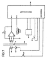
- the outputs of the photodiodes 12-15 are amplified and fed to microprocessor 16 also located in the upper arm 36.
- Photodiodes 13-15 are not illustrated in Fig. 4 , however they are connected to other inputs of the processing unit 16 in a manner similar to that of photodiode 12.
- the processing unit 16 has a built-in A/D converter for converting the input signals into the digital signals to be processed.
- the processing unit may be an 8-bit microprocessor such as that made by Motorola under the serial number 6BHC11E9.
- Microprocessor 16 has an output connected to an indicating unit 18, which has one or more indicators, such as visible flashing LEDs and/or an audible signal generator. Both the processing circuitry 16 and the alarm unit 18 are also powered by the unillustrated battery source. Of course, a remote source of power could be utilised, but such remote source is not necessary providing a sufficiently low amount of power is required by the validator 32.
- the validator 2 is activated by squeezing the upper and lower arms 34,36 together.
- hand grips 20,22 are provided on the hinged end of the validator 32.
- the validator 32 is biassed to an open position, illustrated in Fig. 2 , in which the lower arm 34 and upper arm 36 are held apart.
- the validator may be held by an operator in one hand at the end of the validator at which the grip portions 20 and 22 are located. Meanwhile, a banknote to be validated, held in the operator's other hand, may be inserted in the space between the validator arms 34,36.
- the lower arm 34 and upper arm 36 may be moved together to the activated position shown in Fig. 3 .
- a switch 24 located adjacent the hinged end of the validator 32 is actuated upon closing of the validator arms 34,36.
- the free ends of the arms 34,36 remain spaced apart slightly to allow an inserted banknote lateral freedom of movement between the two arms 34,36.
- the LEDs 10 and photodiodes 12-15 of each sensor pair are in register.
- the LEDs 10 may each be provided with a lens and/or a collimating slit, and the photodiodes 12-15 may be provided with similar optical means to -ensure the sensing of a beam of a desired resolution. Since the windows to be detected may have a width for example of 4 millimetres, it is preferred that the beams sensed are correspondingly narrow to produce the desired resolution. In cases where the validator 32 is intended for use with banknotes having windows of different dimensions, the dimensions of the beams sensed should also correspond to give sufficient resolution.
- the LEDs 10 and/or photodiodes 12-15 may also be provided with filters to ensure sensing at a predetermined wavelength or wavelengths.
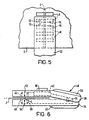
- the banknote 2 is inserted between the validator arms 34,36 such that the security thread 4 lies parallel to, and between, the validator arms 34,36 as shown in Fig. 5 .
- the sensor pairs 10,12-15 are spaced in a direction parallel to the length of the arms 34,36. The spacing is chosen so that when one photodiode 12 is located directly above a window 6 on the banknote 2, adjacent photodiodes 13 is located above a rung 8 between the windows 6 on the banknote.
- the other two photodiodes 14,15 have a similar relationship to one another and are arranged in an offset relation to photodiodes 12,13 so that when a window/rung combination is not clearly detectable by the two photodiodes 12,13, it is nevertheless ensured that a window/rung combination is detected by the two photodiodes 14,15 when the validator 32 is properly located over the security strip.
- the two photodiodes 14,15 are also spaced from the other photodiodes 12,13 in a direction transverse to the length of the arms 34,36 so that, should two of the photodiodes be obscured by the opaque security strip 4, the rungs and windows can still be sensed by the other two photodiodes.
- other arrangements of sensor pairs 10,12-15 could be utilised to similar effect.
- the LEDs 10 When the validator is switched on, the LEDs 10 generate infra-red beams which are transmitted through the banknote to a greater or lesser degree according to the location of the windows 6 and rungs 8, and the photodiodes 12-15 sense the intensity of the transmitted radiation.
- the outputs of the photodiodes 12,13 are compared by the processing unit 16, by taking a ratio, to determine whether the ratio of intensities sensed corresponds to a predetermined value indicating the sensing of a window/rung combination.
- a similar operation could be performed by the use of comparators in addition to the processing unit 16.
- the processing unit 16 performs a similar analysis of the outputs of photodiodes 14,15.
- a validation signal indicating the genuine nature of a banknote 2 is generated, and a "valid" indication is given by the indicator unit 18 in response to a validation signal sent by processing unit 16.
- the indicating unit 18 may be caused to provide an alarm signal should the sensing not produce the desired variation in intensity of transmitted light across the banknote. Such an alarm signal may be produced upon reopening of switch 24 when the validator is released and returned to its open position shown in Fig. 2 .
- the processing unit 16 may analyse the outputs from the photodiodes in ways other than simply taking the ratios of the outputs of photodiodes 12,13 or 14,15. For instance the circuitry 16 may analyse the outputs of the photodiodes to determine whether the absolute intensity of transmitted light sensed at one photodiode falls within a predetermined range of values corresponding to the presence of a window 6, and/or whether the absolute intensity of transmitted light sensed at a different photodiode corresponds with the presence of a rung 8. A difference between the outputs of two photodiodes could also be taken, to determine whether the difference falls within a range of predetermined values which indicate the detection of a window/rung combination.
- the sensors having outputs to be taken in combination need not be aligned in a parallel fashion, since the transmissivity of the banknote 2 could also be sensed not only in the region of windows 6 but also in any other region of the banknotes 2.
- the validator 40 comprises a processing unit 42 (which may be similar to microprocessor 16 described in relation to the previous embodiment) which is responsive to the outputs of two infra-red photodiodes 44,46.
- the photodiodes 44,46 are spaced by an amount greater that the width of the security strip 4 of a banknote to be sensed, for reasons to be explained below.
- LEDs 48,50 generate beams to be sensed by photodiodes 44,46 respectively.
- the output of photodiode 46 although not illustrated in Fig.
- LEDs 48,50 and photodiodes 44,46 may be provided with lenses, collimators or filters as described in relation to the previous embodiment.
- the validator 40 is also normally biassed in an open position, and may be activated by the application of manual pressure to close the arms 34,36. The validator 40 is illustrated in its activated position in Fig. 6 .
- a banknote 2 is inserted between the upper and lower arms 36,34 of the validator 40 as shown in Fig. 8 .
- the banknote is inserted such that the security thread 4 registers at least approximately with arrows 50,52 indicating the general location of the sensor pairs 44,48 and 46,50.
- the activated validator 40 is then swiped relative to the banknote 2 in a direction generally parallel to the security thread 4.
- the profile of an output generated by photodiode 44 when a valid banknote is swiped through the validator 40, or the validator is swiped across the banknote, is as illustrated in Fig. 9 .
- the output (V) is plotted against time (t). Before any part of the banknote passes between the sensor pair 44,48 the output is at a high level H.
- the intensity of transmitted light falls to a low level L.
- a windowed region 6 passes between the sensor pair 44,48 the transmissivity of the material increases due to the reduced thickness and/or density of the paper 5 is in the windowed region 6.
- the output of photodiode 44 then increases to an intermediate level W slightly above the low level L. After passing the first windowed portion 6, the output falls again to the low level L corresponding to the rung region 8, and thereafter the output varies periodically in a regular fashion between the intermediate level W and the low level L as more windows 6 and rungs 8 pass below the photodiode 44.
- the sensor pair 46,50 which is displaced from the sensor pair 44,48 in a direction perpendicular to the security thread 4 of a correctly inserted banknote (as shown in Fig. 8 ) also generally produces the output profile illustrated in Fig. 9 . Therefore, the output of only one of the sensor pairs could generally be used as an indicator of the presence of the exposure windows 6. However, the second sensor pair is provided so that if the radiation beam of one sensor pair is blocked by the security thread 4 itself, or the security strip is at one extreme of the windows 6, the output of the remaining sensor pair can be relied upon to indicate on the presence of windows 6 in a valid banknote 2.
- the processing unit 42 could process the output of one or both sensor pairs in a number of different ways. For instance, the circuitry 42 may determine whether the output during activation of the validator 40 reaches a value within a range of allowed values centred on the low level L, and whether the output reaches one of a range of allowed values centred on the intermediate value W. A validation signal could be provided if both those conditions are met. To provide increased certainty, the number of times at which the output enters each, or one of, those ranges of values may be counted as the banknote is swiped through the validator. When a predetermined count is reached, a validation signal would be generated.
- the high output signal H may be utilised in order to calibrate the output of the photodiodes 44,46 which may vary due to various factors such as battery output power and LED efficiency.
- the profile illustrated in Fig. 9 corresponds to a swipe of relatively constant velocity. With such swipes, the total time over which the output remains at the low level L can be compared to the time over which the output remains at the intermediate level W to measure an aspect ratio which provides a further means of verification of the validity of the banknote 2.
- Non-uniform velocity swipes could be taken account of by sensing the velocity at which the banknote is swiped and compensating appropriately, although this would inevitably increase the complexity and cost of the validator 40.
- a further mode of validation could be provided by using a relatively constant velocity swipe and detecting the leading edge and trailing edge of the banknote 2. The frequency of the detected window portions could then be compared with a predetermined range of frequencies attributed to genuine banknotes.
- FIG. 9 Other embodiments of the invention might include the utilisation of a linear CCD array and an associated illuminating source, which may be moved across the banknote in any direction and the signals appropriately processed to provide validation signals.
- the CCD array could be swiped in a direction either parallel with the security strip 4 or the perpendicular to the security strip 4.
- the CCD array is swiped in a direction perpendicular to the security thread 4, or the CCD array is located directly above the windows 6, an array of outputs having a profile as illustrated in Fig. 9 could be simultaneously generated. If the CCD array were swiped in a direction parallel to security thread 4, at least one of the CCD sensors would generate a time-varying output as illustrated in Fig. 9 .
Landscapes
- Health & Medical Sciences (AREA)
- General Health & Medical Sciences (AREA)
- Toxicology (AREA)
- Physics & Mathematics (AREA)
- General Physics & Mathematics (AREA)
- Inspection Of Paper Currency And Valuable Securities (AREA)
- Paper (AREA)
- Developing Agents For Electrophotography (AREA)
- Medicines Containing Antibodies Or Antigens For Use As Internal Diagnostic Agents (AREA)
- Pharmaceuticals Containing Other Organic And Inorganic Compounds (AREA)
- Investigating Or Analysing Biological Materials (AREA)
Claims (6)
- Validator für Sicherheitsdokumente, wobei der Validator umfaßt:eine Sensorvorrichtung (10, 12 - 15) zum Unterscheiden zwischen echten und gefälschten Sicherheitsdokumenten (2),eine Schaltvorrichtung (24) zum Aktivieren der Sensorvorrichtung (10, 12 - 15) undeine Tragevorrichtung (34, 36) für die Sensorvorrichtung (10, 12 - 15), wobeidie Tragevorrichtung (24, 26) einen ersten Teil (34) und einen zweiten Teil (36) umfaßt, die in einer ersten relativen Position durch eine Öffnung für ein zu validierendes Dokument getrennt sind, und der erste Teil (34) bezüglich des zweiten Teils (36) in eine zweite relative Position bewegbar ist, in welcher die Schaltvorrichtung (24) betätigt wird, und wobei die Sensorvorrichtung eine Strahlenemittiervorrichtung (10) umfaßt, die an dem ersten Teil (34) der Tragevorrichtung angebracht ist und eine Strahlungserfassungsvorrichtung (12 - 15) umfaßt, die an einem zweiten Teil (36) der Tragevorrichtung angebracht ist.
- Validator nach Anspruch 1, wobei die Strahlungserfassungsvorrichtung (12 -15) einen Infrarotstrahlungssensor umfaßt.
- Validator nach einem der Ansprüche 1 bis 2 mit mehreren Strahlungssensoren (12 - 15), die mehrere Ausgaben für deren Analyse an eine Verarbeitungsvorrichtung (16) bereitstellen, um ein Validierungssignal bereitzustellen.
- Validator nach Anspruch 3, wobei die Verarbeitungsvorrichtung (16) zwei oder mehr der Ausgaben in Kombination analysiert, um festzustellen, ob das Validierungssignal ausgegeben werden sollte.
- Validator nach einem der Ansprüche 1 bis 4, der, wenn die Tragevorrichtungen (34, 36) in einer zweiten relativen Position ist, dazu ausgelegt ist, eine zweite Sensorvorrichtung (10, 12 -15) retativ zu einem zu validierenden Dokument (2) zu bewegen, wobei das Dokument zwischen dem ersten und dem zweiten Teil der Tragevorrichtung (34, 36) angeordnet ist.
- Validator nach Anspruch 5, wobei in der zweiten relativen Position der erste und der zweite Teil (34, 36) der Tragevorrichtung durch eine Öffnung getrennt bleiben, um ein zu validierendes Dokument (2) relativ zu den Sensorvorrichtungen (10, 12 - 15) bewegen zu können.
Applications Claiming Priority (3)
| Application Number | Priority Date | Filing Date | Title |
|---|---|---|---|
| GB9602260A GB2309778B (en) | 1996-02-05 | 1996-02-05 | Security document validation |
| GB9602260 | 1996-02-05 | ||
| PCT/GB1997/000321 WO1997029459A1 (en) | 1996-02-05 | 1997-02-05 | Security document validation |
Publications (3)
| Publication Number | Publication Date |
|---|---|
| EP0891608A1 EP0891608A1 (de) | 1999-01-20 |
| EP0891608B1 EP0891608B1 (de) | 2003-11-12 |
| EP0891608B2 true EP0891608B2 (de) | 2008-11-05 |
Family
ID=10788117
Family Applications (1)
| Application Number | Title | Priority Date | Filing Date |
|---|---|---|---|
| EP97902474A Expired - Lifetime EP0891608B2 (de) | 1996-02-05 | 1997-02-05 | Prüfung von sicherheitsdokumenten |
Country Status (8)
| Country | Link |
|---|---|
| US (1) | US6438262B1 (de) |
| EP (1) | EP0891608B2 (de) |
| AT (1) | ATE254319T1 (de) |
| AU (1) | AU1611297A (de) |
| DE (1) | DE69726132T3 (de) |
| ES (1) | ES2208869T5 (de) |
| GB (1) | GB2309778B (de) |
| WO (1) | WO1997029459A1 (de) |
Families Citing this family (45)
| Publication number | Priority date | Publication date | Assignee | Title |
|---|---|---|---|---|
| US6363164B1 (en) | 1996-05-13 | 2002-03-26 | Cummins-Allison Corp. | Automated document processing system using full image scanning |
| US6661910B2 (en) | 1997-04-14 | 2003-12-09 | Cummins-Allison Corp. | Network for transporting and processing images in real time |
| US7903863B2 (en) | 2001-09-27 | 2011-03-08 | Cummins-Allison Corp. | Currency bill tracking system |
| US7187795B2 (en) | 2001-09-27 | 2007-03-06 | Cummins-Allison Corp. | Document processing system using full image scanning |
| US20050276458A1 (en) | 2004-05-25 | 2005-12-15 | Cummins-Allison Corp. | Automated document processing system and method using image scanning |
| US8162125B1 (en) | 1996-05-29 | 2012-04-24 | Cummins-Allison Corp. | Apparatus and system for imaging currency bills and financial documents and method for using the same |
| US8478020B1 (en) | 1996-11-27 | 2013-07-02 | Cummins-Allison Corp. | Apparatus and system for imaging currency bills and financial documents and method for using the same |
| US8701857B2 (en) | 2000-02-11 | 2014-04-22 | Cummins-Allison Corp. | System and method for processing currency bills and tickets |
| JP2001344635A (ja) * | 2000-06-02 | 2001-12-14 | Birukon Kk | 紙葉類識別計数機およびその識別計数方法 |
| US7000828B2 (en) | 2001-04-10 | 2006-02-21 | Cummins-Allison Corp. | Remote automated document processing system |
| US7647275B2 (en) | 2001-07-05 | 2010-01-12 | Cummins-Allison Corp. | Automated payment system and method |
| US8437530B1 (en) | 2001-09-27 | 2013-05-07 | Cummins-Allison Corp. | Apparatus and system for imaging currency bills and financial documents and method for using the same |
| US8433123B1 (en) | 2001-09-27 | 2013-04-30 | Cummins-Allison Corp. | Apparatus and system for imaging currency bills and financial documents and method for using the same |
| US8437529B1 (en) | 2001-09-27 | 2013-05-07 | Cummins-Allison Corp. | Apparatus and system for imaging currency bills and financial documents and method for using the same |
| US8944234B1 (en) | 2001-09-27 | 2015-02-03 | Cummins-Allison Corp. | Apparatus and system for imaging currency bills and financial documents and method for using the same |
| US8428332B1 (en) | 2001-09-27 | 2013-04-23 | Cummins-Allison Corp. | Apparatus and system for imaging currency bills and financial documents and method for using the same |
| DE20118645U1 (de) * | 2001-11-15 | 2002-01-17 | Yu, Hung-Ming, Xin-Zhuang, Taipeh | Scheinprüfer mit einer vorderen Klappe |
| US6896118B2 (en) | 2002-01-10 | 2005-05-24 | Cummins-Allison Corp. | Coin redemption system |
| EP1376484A1 (de) * | 2002-06-25 | 2004-01-02 | Mars Incorporated | Verfahren und Vorrichtung zur Signalverarbeitung in der Geldprüfung |
| US8627939B1 (en) | 2002-09-25 | 2014-01-14 | Cummins-Allison Corp. | Apparatus and system for imaging currency bills and financial documents and method for using the same |
| JP4366104B2 (ja) * | 2003-04-17 | 2009-11-18 | 日立オムロンターミナルソリューションズ株式会社 | 紙葉類判別装置 |
| DE10346635A1 (de) * | 2003-10-08 | 2005-05-12 | Giesecke & Devrient Gmbh | System zur Prüfung von Sicherheitsmerkmalen von Wertdokumenten |
| RU2274900C2 (ru) * | 2004-02-25 | 2006-04-20 | Ооо "Вилдис" | Устройство для проверки подлинности банкнот |
| WO2005086099A1 (en) * | 2004-03-08 | 2005-09-15 | Council Of Scientific & Industrial Research | Improved fake currency detector using integrated transmission and reflective spectral response |
| US20050259858A1 (en) * | 2004-05-24 | 2005-11-24 | Eins Oe-Tech Co., Ltd. | Money checking apparatus |
| DE102004049998A1 (de) * | 2004-10-14 | 2006-04-20 | Giesecke & Devrient Gmbh | Vorrichtung und Verfahren zur visuellen Darstellung von Meßwerten |
| GB0525664D0 (en) | 2005-12-16 | 2006-01-25 | Filtrona Plc | Detector |
| WO2007101673A1 (de) | 2006-03-07 | 2007-09-13 | Bundesdruckerei Gmbh | Mobile verifikationseinrichtung zur echtheitsüberprüfung von ausweisdokumenten |
| US20080173832A1 (en) * | 2007-01-24 | 2008-07-24 | International Currency Technologies Corporation | Valuable paper validator |
| US8417017B1 (en) | 2007-03-09 | 2013-04-09 | Cummins-Allison Corp. | Apparatus and system for imaging currency bills and financial documents and method for using the same |
| US8538123B1 (en) | 2007-03-09 | 2013-09-17 | Cummins-Allison Corp. | Apparatus and system for imaging currency bills and financial documents and method for using the same |
| CA2677714C (en) | 2007-03-09 | 2014-12-23 | Cummins-Allison Corp. | Document imaging and processing system |
| RU2007113953A (ru) * | 2007-04-16 | 2008-10-27 | Сергей Николаевич Максимовский (RU) | Мобильный телефон |
| EP2168104A1 (de) | 2007-06-06 | 2010-03-31 | De La Rue International Limited | Vorrichtung zum analysieren eines sicherheitsdokuments |
| WO2008149050A1 (en) * | 2007-06-06 | 2008-12-11 | De La Rue International Limited | Apparatus for analysing a security document |
| US20100206779A1 (en) * | 2007-06-06 | 2010-08-19 | De La Rue International Limited | Apparatus and method for analysing a security document |
| US20110133442A1 (en) * | 2008-06-12 | 2011-06-09 | Crane Douglas A | Method for increasing adhesion between a security element and a fibrous sheet material |
| US8391583B1 (en) | 2009-04-15 | 2013-03-05 | Cummins-Allison Corp. | Apparatus and system for imaging currency bills and financial documents and method for using the same |
| US8478019B1 (en) | 2009-04-15 | 2013-07-02 | Cummins-Allison Corp. | Apparatus and system for imaging currency bills and financial documents and method for using the same |
| US8929640B1 (en) | 2009-04-15 | 2015-01-06 | Cummins-Allison Corp. | Apparatus and system for imaging currency bills and financial documents and method for using the same |
| GB201100803D0 (en) * | 2011-01-18 | 2011-03-02 | Innovative Technology Ltd | Apparatus and method for generating dataset for items of currency |
| US9708773B2 (en) | 2011-02-23 | 2017-07-18 | Crane & Co., Inc. | Security sheet or document having one or more enhanced watermarks |
| MD4195C1 (ro) * | 2011-05-12 | 2013-08-31 | Сергей Васильев | Procedeu de verificare a autenticităţii hârtiilor de valoare şi dispozitiv pentru realizarea acestuia (variante) |
| US9141876B1 (en) | 2013-02-22 | 2015-09-22 | Cummins-Allison Corp. | Apparatus and system for processing currency bills and financial documents and method for using the same |
| GB201403988D0 (en) * | 2014-03-06 | 2014-04-23 | Rue De Int Ltd | Security documents and methods of manufacture thereof |
Family Cites Families (27)
| Publication number | Priority date | Publication date | Assignee | Title |
|---|---|---|---|---|
| IT941586B (it) * | 1971-10-15 | 1973-03-10 | Martelli M | Apparecchio verificatore di carte valori ed in specie di banconote a funzionamento fotoelettrico |
| AT334118B (de) * | 1975-07-15 | 1976-12-27 | Gao Ges Automation Org | Messvorrichtung zum messen von dickenunterschieden in aufzeichnungstragern, wie banknoten u.dgl. |
| GB1604463A (en) | 1976-09-24 | 1981-12-09 | Bank Of England | Security devices |
| GB1552853A (en) * | 1976-09-24 | 1979-09-19 | Bank Of England | Authentication devices |
| US4287414A (en) | 1979-06-29 | 1981-09-01 | International Business Machines Corp. | Illumination and pick up apparatus |
| IN157644B (de) | 1981-02-19 | 1986-05-10 | Portals Ltd | |
| AU556102B2 (en) * | 1981-10-22 | 1986-10-23 | Cubic Western Data | Currency note validator |
| JPS58175091A (ja) | 1982-04-06 | 1983-10-14 | 株式会社東芝 | セキユリテイ・ストレツド検出装置 |
| SE434090B (sv) * | 1982-11-18 | 1984-07-02 | Esselte Security Syst Ab | Anordning for astadkommande och detektering av ett spaltformigt stralknippe av ljus |
| GB8311795D0 (en) | 1983-04-29 | 1983-06-02 | De La Rue Syst | Detecting luminescent security features |
| US4558224A (en) | 1983-05-26 | 1985-12-10 | Imperial Inc. | Counterfeit bill warning device |
| DE3601114A1 (de) | 1986-01-16 | 1987-07-23 | Gao Ges Automation Org | Verfahren zur herstellung von sichrheitspapier mit eingelagertem sicherheitsfaden |
| US4881268A (en) * | 1986-06-17 | 1989-11-14 | Laurel Bank Machines Co., Ltd. | Paper money discriminator |
| US4748679A (en) * | 1986-07-25 | 1988-05-31 | Light Signatures, Inc. | Weighted-pixel characteristic sensing system |
| MY102798A (en) * | 1987-12-04 | 1992-10-31 | Portals Ltd | Security paper for bank notes and the like |
| US4984280A (en) * | 1988-06-08 | 1991-01-08 | Laurel Bank Machines Co., Ltd. | Bill discriminating apparatus |
| FR2642199B1 (fr) * | 1989-01-23 | 1992-04-10 | Arjomari Prioux | Procede de reconnaissance d'images par rayonnements electromagnetiques et dispositifs pour la mise en oeuvre d'un tel procede |
| GB8912750D0 (en) | 1989-06-02 | 1989-07-19 | Portals Ltd | Security paper |
| DE4001716A1 (de) * | 1990-01-22 | 1991-07-25 | Nsm Ag | Pruefgeraet fuer banknoten |
| GB9019784D0 (en) * | 1990-09-10 | 1990-10-24 | Amblehurst Ltd | Security device |
| GB2250474B (en) | 1990-12-04 | 1994-04-20 | Portals Ltd | Security articles |
| FR2677676A1 (fr) | 1991-06-12 | 1992-12-18 | Arjo Wiggins Sa | Document de securite contenant un fil opaque presentant des marques iridescentes. |
| US5260582A (en) * | 1992-04-20 | 1993-11-09 | Danek Robert J | Currency verification device for detecting the presence or the absence of security threads |
| GB9214664D0 (en) * | 1992-07-10 | 1992-08-19 | Wiggins Teape Group Ltd | Watermark detection |
| WO1994016412A1 (en) | 1993-01-09 | 1994-07-21 | Mars, Incorporated | Detection of counterfeit objects |
| IT1271191B (it) | 1994-06-22 | 1997-05-27 | Mantegazza A Arti Grafici | Apparecchiatura di lettura per la rilevazione della presenza e per la decodifica di fili di sicurezza in documenti a conformazione lastriforme |
| US5639126A (en) * | 1995-06-06 | 1997-06-17 | Crane & Co., Inc. | Machine readable and visually verifiable security threads and security papers employing same |
-
1996
- 1996-02-05 GB GB9602260A patent/GB2309778B/en not_active Expired - Fee Related
-
1997
- 1997-02-05 US US09/117,668 patent/US6438262B1/en not_active Expired - Fee Related
- 1997-02-05 EP EP97902474A patent/EP0891608B2/de not_active Expired - Lifetime
- 1997-02-05 WO PCT/GB1997/000321 patent/WO1997029459A1/en not_active Ceased
- 1997-02-05 ES ES97902474T patent/ES2208869T5/es not_active Expired - Lifetime
- 1997-02-05 DE DE69726132T patent/DE69726132T3/de not_active Expired - Lifetime
- 1997-02-05 AU AU16112/97A patent/AU1611297A/en not_active Abandoned
- 1997-02-05 AT AT97902474T patent/ATE254319T1/de not_active IP Right Cessation
Also Published As
| Publication number | Publication date |
|---|---|
| GB2309778A (en) | 1997-08-06 |
| DE69726132T2 (de) | 2004-07-22 |
| GB2309778B (en) | 2000-05-24 |
| DE69726132D1 (de) | 2003-12-18 |
| DE69726132T3 (de) | 2009-07-09 |
| AU1611297A (en) | 1997-08-28 |
| US6438262B1 (en) | 2002-08-20 |
| ATE254319T1 (de) | 2003-11-15 |
| GB9602260D0 (en) | 1996-04-03 |
| ES2208869T3 (es) | 2004-06-16 |
| EP0891608B1 (de) | 2003-11-12 |
| WO1997029459A1 (en) | 1997-08-14 |
| ES2208869T5 (es) | 2009-06-22 |
| EP0891608A1 (de) | 1999-01-20 |
Similar Documents
| Publication | Publication Date | Title |
|---|---|---|
| EP0891608B1 (de) | Prüfung von sicherheitsdokumenten | |
| US5915518A (en) | Detection of counterfeit objects, for instance counterfeit banknotes | |
| US5918960A (en) | Detection of counterfeit objects, for instance counterfeit banknotes | |
| KR101297702B1 (ko) | 적분된 투과 및 반사 스펙트럼 응답을 이용한 개선된 위조 화폐 검출기 | |
| US5034616A (en) | Device for optically scanning sheet-like documents | |
| CA2559102C (en) | Improved fake currency detector using visual and reflective spectral response | |
| GB2355522A (en) | Improvements in verifying printed security substrates | |
| KR100661440B1 (ko) | 종이류 특징 검출 장치 및 종이류 특징 검출 방법 | |
| EP1849138B1 (de) | Verbesserungen in bezug auf die banknotenvalidierung | |
| KR100597789B1 (ko) | 반사식 광학센서를 이용한 지폐식별장치 | |
| US20160210804A1 (en) | Authentication apparatus and method | |
| FI85312B (fi) | Anordning foer granskning av sedlars autenticitet. | |
| JP4074917B1 (ja) | 紙葉類識別装置 | |
| JPH0944633A (ja) | 紙葉類鑑別装置 | |
| RU2736700C2 (ru) | Аппарат и способ для обработки банкнот | |
| JP2655169B2 (ja) | 紙幣識別方法 | |
| RU2115169C1 (ru) | Способ определения подлинности банкноты | |
| JP2896288B2 (ja) | 紙幣識別方法 | |
| AU737427B3 (en) | High intelligence bank note reader with function of multi-spectral sensor auto note face searching and UV counterfeit detection | |
| GB2444966A (en) | Validating sheet objects with a barcode and money value | |
| KR101037696B1 (ko) | 은선감지장치의 제어방법 | |
| GB2291705A (en) | Detection of counterfeit bank notes | |
| KR20090008708A (ko) | 컨택 이미지 센서를 이용한 위폐 식별방법 | |
| JPH10111967A (ja) | 紙幣識別装置 | |
| JPH0793634A (ja) | 紙幣識別装置 |
Legal Events
| Date | Code | Title | Description |
|---|---|---|---|
| PUAI | Public reference made under article 153(3) epc to a published international application that has entered the european phase |
Free format text: ORIGINAL CODE: 0009012 |
|
| 17P | Request for examination filed |
Effective date: 19980828 |
|
| AK | Designated contracting states |
Kind code of ref document: A1 Designated state(s): AT DE ES FR GB IT NL |
|
| 17Q | First examination report despatched |
Effective date: 20001218 |
|
| GRAH | Despatch of communication of intention to grant a patent |
Free format text: ORIGINAL CODE: EPIDOS IGRA |
|
| GRAS | Grant fee paid |
Free format text: ORIGINAL CODE: EPIDOSNIGR3 |
|
| GRAA | (expected) grant |
Free format text: ORIGINAL CODE: 0009210 |
|
| AK | Designated contracting states |
Kind code of ref document: B1 Designated state(s): AT DE ES FR GB IT NL |
|
| PG25 | Lapsed in a contracting state [announced via postgrant information from national office to epo] |
Ref country code: NL Free format text: LAPSE BECAUSE OF FAILURE TO SUBMIT A TRANSLATION OF THE DESCRIPTION OR TO PAY THE FEE WITHIN THE PRESCRIBED TIME-LIMIT Effective date: 20031112 Ref country code: FR Free format text: LAPSE BECAUSE OF FAILURE TO SUBMIT A TRANSLATION OF THE DESCRIPTION OR TO PAY THE FEE WITHIN THE PRESCRIBED TIME-LIMIT Effective date: 20031112 Ref country code: AT Free format text: LAPSE BECAUSE OF FAILURE TO SUBMIT A TRANSLATION OF THE DESCRIPTION OR TO PAY THE FEE WITHIN THE PRESCRIBED TIME-LIMIT Effective date: 20031112 |
|
| REG | Reference to a national code |
Ref country code: GB Ref legal event code: FG4D |
|
| REF | Corresponds to: |
Ref document number: 69726132 Country of ref document: DE Date of ref document: 20031218 Kind code of ref document: P |
|
| NLV1 | Nl: lapsed or annulled due to failure to fulfill the requirements of art. 29p and 29m of the patents act | ||
| REG | Reference to a national code |
Ref country code: ES Ref legal event code: FG2A Ref document number: 2208869 Country of ref document: ES Kind code of ref document: T3 |
|
| PLBQ | Unpublished change to opponent data |
Free format text: ORIGINAL CODE: EPIDOS OPPO |
|
| PLBI | Opposition filed |
Free format text: ORIGINAL CODE: 0009260 |
|
| PLAX | Notice of opposition and request to file observation + time limit sent |
Free format text: ORIGINAL CODE: EPIDOSNOBS2 |
|
| 26 | Opposition filed |
Opponent name: DE LA RUE INTERNATIONAL LIMITED Effective date: 20040811 |
|
| EN | Fr: translation not filed | ||
| PLAX | Notice of opposition and request to file observation + time limit sent |
Free format text: ORIGINAL CODE: EPIDOSNOBS2 |
|
| PLAX | Notice of opposition and request to file observation + time limit sent |
Free format text: ORIGINAL CODE: EPIDOSNOBS2 |
|
| PLBB | Reply of patent proprietor to notice(s) of opposition received |
Free format text: ORIGINAL CODE: EPIDOSNOBS3 |
|
| REG | Reference to a national code |
Ref country code: HK Ref legal event code: WD Ref document number: 1018653 Country of ref document: HK |
|
| REG | Reference to a national code |
Ref country code: GB Ref legal event code: 732E |
|
| RAP2 | Party data changed (patent owner data changed or rights of a patent transferred) |
Owner name: MEI, INC. |
|
| REG | Reference to a national code |
Ref country code: GB Ref legal event code: 732E |
|
| APBP | Date of receipt of notice of appeal recorded |
Free format text: ORIGINAL CODE: EPIDOSNNOA2O |
|
| APAH | Appeal reference modified |
Free format text: ORIGINAL CODE: EPIDOSCREFNO |
|
| APBU | Appeal procedure closed |
Free format text: ORIGINAL CODE: EPIDOSNNOA9O |
|
| PUAH | Patent maintained in amended form |
Free format text: ORIGINAL CODE: 0009272 |
|
| STAA | Information on the status of an ep patent application or granted ep patent |
Free format text: STATUS: PATENT MAINTAINED AS AMENDED |
|
| 27A | Patent maintained in amended form |
Effective date: 20081105 |
|
| AK | Designated contracting states |
Kind code of ref document: B2 Designated state(s): AT DE ES FR GB IT NL |
|
| REG | Reference to a national code |
Ref country code: ES Ref legal event code: DC2A Date of ref document: 20081230 Kind code of ref document: T5 |
|
| PGFP | Annual fee paid to national office [announced via postgrant information from national office to epo] |
Ref country code: DE Payment date: 20110208 Year of fee payment: 15 Ref country code: IT Payment date: 20110212 Year of fee payment: 15 |
|
| PGFP | Annual fee paid to national office [announced via postgrant information from national office to epo] |
Ref country code: ES Payment date: 20110315 Year of fee payment: 15 Ref country code: GB Payment date: 20110209 Year of fee payment: 15 |
|
| GBPC | Gb: european patent ceased through non-payment of renewal fee |
Effective date: 20120205 |
|
| PG25 | Lapsed in a contracting state [announced via postgrant information from national office to epo] |
Ref country code: IT Free format text: LAPSE BECAUSE OF NON-PAYMENT OF DUE FEES Effective date: 20120205 |
|
| REG | Reference to a national code |
Ref country code: DE Ref legal event code: R119 Ref document number: 69726132 Country of ref document: DE Effective date: 20120901 |
|
| PG25 | Lapsed in a contracting state [announced via postgrant information from national office to epo] |
Ref country code: GB Free format text: LAPSE BECAUSE OF NON-PAYMENT OF DUE FEES Effective date: 20120205 |
|
| PG25 | Lapsed in a contracting state [announced via postgrant information from national office to epo] |
Ref country code: DE Free format text: LAPSE BECAUSE OF NON-PAYMENT OF DUE FEES Effective date: 20120901 |
|
| REG | Reference to a national code |
Ref country code: ES Ref legal event code: FD2A Effective date: 20130708 |
|
| PG25 | Lapsed in a contracting state [announced via postgrant information from national office to epo] |
Ref country code: ES Free format text: LAPSE BECAUSE OF NON-PAYMENT OF DUE FEES Effective date: 20120206 |