EP0891703A1 - Vorrichtung zur Aufbereitung und Verteilung von Viehfutter - Google Patents
Vorrichtung zur Aufbereitung und Verteilung von Viehfutter Download PDFInfo
- Publication number
- EP0891703A1 EP0891703A1 EP98440151A EP98440151A EP0891703A1 EP 0891703 A1 EP0891703 A1 EP 0891703A1 EP 98440151 A EP98440151 A EP 98440151A EP 98440151 A EP98440151 A EP 98440151A EP 0891703 A1 EP0891703 A1 EP 0891703A1
- Authority
- EP
- European Patent Office
- Prior art keywords
- tank
- screws
- machine according
- food
- counter knife
- Prior art date
- Legal status (The legal status is an assumption and is not a legal conclusion. Google has not performed a legal analysis and makes no representation as to the accuracy of the status listed.)
- Granted
Links
- 241001465754 Metazoa Species 0.000 title description 4
- 235000013305 food Nutrition 0.000 claims abstract description 32
- 238000004804 winding Methods 0.000 claims description 3
- 244000144972 livestock Species 0.000 claims description 2
- 239000000203 mixture Substances 0.000 description 6
- 239000000463 material Substances 0.000 description 3
- 241000283690 Bos taurus Species 0.000 description 1
- 230000005484 gravity Effects 0.000 description 1
- 239000008240 homogeneous mixture Substances 0.000 description 1
- 238000012986 modification Methods 0.000 description 1
- 230000004048 modification Effects 0.000 description 1
- 235000011837 pasties Nutrition 0.000 description 1
- 208000026438 poor feeding Diseases 0.000 description 1
- 238000002360 preparation method Methods 0.000 description 1
- 238000011084 recovery Methods 0.000 description 1
- 238000006467 substitution reaction Methods 0.000 description 1
Images

Classifications
-
- A—HUMAN NECESSITIES
- A01—AGRICULTURE; FORESTRY; ANIMAL HUSBANDRY; HUNTING; TRAPPING; FISHING
- A01F—PROCESSING OF HARVESTED PRODUCE; HAY OR STRAW PRESSES; DEVICES FOR STORING AGRICULTURAL OR HORTICULTURAL PRODUCE
- A01F29/00—Cutting apparatus specially adapted for cutting hay, straw or the like
- A01F29/005—Cutting apparatus specially adapted for cutting hay, straw or the like for disintegrating and cutting up bales of hay, straw or fodder
-
- A—HUMAN NECESSITIES
- A01—AGRICULTURE; FORESTRY; ANIMAL HUSBANDRY; HUNTING; TRAPPING; FISHING
- A01K—ANIMAL HUSBANDRY; AVICULTURE; APICULTURE; PISCICULTURE; FISHING; REARING OR BREEDING ANIMALS, NOT OTHERWISE PROVIDED FOR; NEW BREEDS OF ANIMALS
- A01K5/00—Feeding devices for stock or game ; Feeding wagons; Feeding stacks
- A01K5/001—Fodder distributors with mixer or shredder
- A01K5/002—Fodder distributors with mixer or shredder with mixing or shredding element rotating on horizontal axis
-
- B—PERFORMING OPERATIONS; TRANSPORTING
- B01—PHYSICAL OR CHEMICAL PROCESSES OR APPARATUS IN GENERAL
- B01F—MIXING, e.g. DISSOLVING, EMULSIFYING OR DISPERSING
- B01F27/00—Mixers with rotary stirring devices in fixed receptacles; Kneaders
- B01F27/60—Mixers with rotary stirring devices in fixed receptacles; Kneaders with stirrers rotating about a horizontal or inclined axis
- B01F27/72—Mixers with rotary stirring devices in fixed receptacles; Kneaders with stirrers rotating about a horizontal or inclined axis with helices or sections of helices
- B01F27/726—Mixers with rotary stirring devices in fixed receptacles; Kneaders with stirrers rotating about a horizontal or inclined axis with helices or sections of helices with two helices with opposite pitch on the same shaft; with two helices on the same axis, driven in opposite directions or at different speeds
-
- B—PERFORMING OPERATIONS; TRANSPORTING
- B01—PHYSICAL OR CHEMICAL PROCESSES OR APPARATUS IN GENERAL
- B01F—MIXING, e.g. DISSOLVING, EMULSIFYING OR DISPERSING
- B01F33/00—Other mixers; Mixing plants; Combinations of mixers
- B01F33/50—Movable or transportable mixing devices or plants
- B01F33/502—Vehicle-mounted mixing devices
- B01F33/5023—Vehicle-mounted mixing devices the vehicle being a trailer which is hand moved or coupled to self-propelling vehicles
-
- B—PERFORMING OPERATIONS; TRANSPORTING
- B01—PHYSICAL OR CHEMICAL PROCESSES OR APPARATUS IN GENERAL
- B01F—MIXING, e.g. DISSOLVING, EMULSIFYING OR DISPERSING
- B01F2101/00—Mixing characterised by the nature of the mixed materials or by the application field
- B01F2101/06—Mixing of food ingredients
- B01F2101/18—Mixing animal food ingredients
-
- B—PERFORMING OPERATIONS; TRANSPORTING
- B01—PHYSICAL OR CHEMICAL PROCESSES OR APPARATUS IN GENERAL
- B01F—MIXING, e.g. DISSOLVING, EMULSIFYING OR DISPERSING
- B01F33/00—Other mixers; Mixing plants; Combinations of mixers
- B01F33/50—Movable or transportable mixing devices or plants
- B01F33/502—Vehicle-mounted mixing devices
Definitions
- the present invention relates to a machine for preparing and distribution of animal feed.
- This machine includes in particular a chassis, a tank which is mounted on said chassis and which is formed by at least one floor, two side walls, a front wall and a rear wall defining a volume can be filled with food, shredding and mixing means which are located in the tank, which means consist of at least two screws substantially horizontal which are housed in the bottom of the tank, which are rotated in opposite directions and which are fitted with threads or blades opposite winding directions to move food from the front walls and back towards the middle of the tank and by at least one counter knife located between said screws and extending over at least part of their length.
- Machines of this kind are used to mix different kinds wet or dry, hard or pasty food, in long or short strands, loose or compact, in order to obtain a homogeneous structure which can then be distributed To animals.
- food is usually introduced into the tank from above. They are then shredded by the screws located in the bottom of the tank and moved by them towards the middle of said tank. The force exerted by the meeting in the middle of the two masses makes the material go up along the walls side. It then falls by gravity towards the front and rear of the tank and is recovery by screws. After several passages we should obtain a mixture whose composition is perfectly uniform.
- the present invention aims to remedy the aforementioned drawbacks. She must in particular ensure good circulation of all food in order to improve the homogeneity of the mixture obtained.
- an important characteristic of the invention consists in that the counter knife has an upper edge which is inclined over at least part of its length so that it is further from the floor of the tank in the middle of the latter only near its front and rear walls and by the fact that said walls front and rear are at least partially inclined towards the middle of the tank.
- the counter knife favors, due to its position, food engagement in the screws at both ends of these. However, it somehow slows down their engagement in said screws in the central parts thereof. We thus obtain a regulation of the taking of the material by screws. This promotes the flow of all the food in the part high of the tank from the middle of it to its two ends. In this way food mixes optimally.
- the counter knife is made of several segments.
- the height position of these segments can be adjustable. This allows in particular to modulate the entry of food into the screws depending on their nature.
- the front and rear walls of the tank can be partially tilted towards the middle and form angles of about 30 ° with the vertical. Said angles can be adjustable in order to adapt the position of the walls to the nature of the food loaded in the tank.
- the machine comprises a chassis (1). This is fitted with wheels (2 and 3) and a drawbar (4) for attachment to a tractor not shown.
- a tank (5) formed by at least one floor (6), two side walls (7 and 8), a front wall (9) and a rear wall (10) defining a volume which can be filled with food.
- At least one of these walls (7 and 8) has an opening (11) in the lower part for removing food. It can be closed through a door.
- In the bottom of the tank (5) are housed shredding means and mixing (12) food. They consist of two screws (13 and 14) substantially horizontal and by at least one counter knife (15) which is located between said screws (13 and 14).
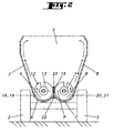
- screws (13 and 14) are mounted in bearings of the front and rear walls (9 and 10) so that it can rotate. They can be rotated in reverse directions as indicated by the arrows (A and B) in Figure 2. They then rotate in convergence towards the counter knife (15).
- This training is provided by chains which pass on wheels integral with screws (13 and 14) and a drive wheel which is integral with a shaft (16) which can be connected to a drive shaft force of the tractor.
- the screw drive means (13 and 14) can also be constituted by gear wheels which mesh. They are housed in a housing (17) located against the outside of the front wall (9) of the tank (5).
- Each screw (13 and 14) is provided with threads (18 and 19, 20 and 21) one way of opposite windings, so as to move the food from their ends front and back towards the middle.
- the two threads (18 and 19, 20 and 21) of each screw (13 and 14) can have identical or slightly different lengths.
- the nets (18 to 21) can be replaced by blades oriented in the same way. They can be equipped with their periphery of knives or the like.
- the counter knife (15) extends substantially over the entire length of the screws (13 and 14) or over a significant part of their length. It can be done in one piece or in several segments (24 to 27). It is fixed on a heel (22) which is integral with the floor (6) of the tank (5). As shown in Figure 1, this counter knife (15) has an upper edge (23) which is inclined on at least part of its length so that it is further from the floor (6) of the tank (5) towards the middle of it only near its front and rear walls (9 and 10).
- said upper edge (23) is located below a plane (P) passing through the axes of rotation of the screws (13 and 14) in the vicinity of the front and rear walls (9 and 10) of the tank (5) and above said plane (P) in the central part of the tank (5).
- the position in the height direction of the counter knife (15) is advantageously adjustable. This makes it possible to adapt its position relative to the screws (13 and 14) depending on the nature of the food loaded in the tank (5). In view of this adjustment, you can change the position of the counter knife (15) on the heel (22) or well modify the position of the latter by making it penetrate more or less high in the tank (5).
- the segments (24 to 27) are located in continuation of each other. Such segments are easier to achieve. They have the shape of a U, which allows them to overlap the heel (22) of the tank (5) (see Figure 2). Their upper edge (23) can be serrated. The width of said edge may also vary.
- Each segment (24 to 27) is fixed on the heel (22) with bolts (28) passing through. They have several holes of passage (29), located one above the other, for said bolts (28). Each can thus be fixed in different positions in the height direction. It is so possible to modify the position and / or the inclination of their upper edge (23) by relative to the floor (6).
- each inclined part (30 and 31) is linked to the remaining part of the front (9) or rear (10) wall by means of a hinge. This allows you to adjust the inclination of the parts (30 and 31) according to the needs.
- front and rear walls (9 and 10) have upper edges (32 and 33) which are directed outwards. These flared edges (32 and 33) favor the introduction of food from above into the tank (5).
- the user loads the various feeds into the tank (5) by the top. Then it turns the screws (13 and 14) in the direction of the arrows (A and B) to obtain a grinding and a mixture of these foods. During this operation, the food engages in the screws (13 and 14) essentially near the ends front and back of these. They are then moved by the nets (18 to 21) towards the middle of tank (5). During each passage between the screws (13 and 14) and the counter knife (15) the food is cut in order to obtain strands or pieces of relatively uniform size.
- the food then describes the trajectories indicated by the arrows (C and D) in Figure 1. These provide a perfectly homogeneous mixture.
- the user can then bring the machine to the feeding area and distribute feeding the animals by bringing it out through the orifice (11).
Landscapes
- Life Sciences & Earth Sciences (AREA)
- Chemical & Material Sciences (AREA)
- Chemical Kinetics & Catalysis (AREA)
- Environmental Sciences (AREA)
- Birds (AREA)
- Animal Husbandry (AREA)
- Biodiversity & Conservation Biology (AREA)
- Apparatuses For Bulk Treatment Of Fruits And Vegetables And Apparatuses For Preparing Feeds (AREA)
Applications Claiming Priority (2)
| Application Number | Priority Date | Filing Date | Title |
|---|---|---|---|
| FR9709322A FR2766061B1 (fr) | 1997-07-18 | 1997-07-18 | Machine de preparation et de distribution d'aliments pour le betail |
| FR9709322 | 1997-07-18 |
Publications (2)
| Publication Number | Publication Date |
|---|---|
| EP0891703A1 true EP0891703A1 (de) | 1999-01-20 |
| EP0891703B1 EP0891703B1 (de) | 2002-10-09 |
Family
ID=9509505
Family Applications (1)
| Application Number | Title | Priority Date | Filing Date |
|---|---|---|---|
| EP98440151A Expired - Lifetime EP0891703B1 (de) | 1997-07-18 | 1998-07-03 | Vorrichtung zur Aufbereitung und Verteilung von Viehfutter |
Country Status (4)
| Country | Link |
|---|---|
| EP (1) | EP0891703B1 (de) |
| DE (1) | DE69808563T2 (de) |
| DK (1) | DK0891703T3 (de) |
| FR (1) | FR2766061B1 (de) |
Cited By (4)
| Publication number | Priority date | Publication date | Assignee | Title |
|---|---|---|---|---|
| WO1999025181A1 (en) * | 1997-11-13 | 1999-05-27 | Giuseppe Loppoli | Cutting-mixing-feeding wagon for forage and grass or straw silage provided with a container with an improved inside profile |
| WO2001008471A1 (en) * | 1999-07-29 | 2001-02-08 | Saverio Pagano | Wagon for the preparation and distribution of animal foodstuff |
| US7614332B2 (en) | 2003-10-23 | 2009-11-10 | Tac-Fast Georgia, Llc | Carpet beveller |
| CN106135031A (zh) * | 2016-08-22 | 2016-11-23 | 无锡东晟生物科技有限公司 | 一种具有粉碎功能的宠物用喂食装置 |
Citations (2)
| Publication number | Priority date | Publication date | Assignee | Title |
|---|---|---|---|---|
| EP0352670A2 (de) * | 1988-07-29 | 1990-01-31 | SEKO S.p.A. | Anhänger zum Zerkleinern, Mischen und Verteilen, insbesondere von zylinderförmigen und prismaförmigen Futter-, Heu- und Grasballen |
| WO1997017841A1 (en) * | 1995-11-14 | 1997-05-22 | Seko S.P.A. | Cutter-mixer-feeder wagon for fodder and grass or straw silage, provided with profiled plate to convey the material to be processed |
-
1997
- 1997-07-18 FR FR9709322A patent/FR2766061B1/fr not_active Expired - Fee Related
-
1998
- 1998-07-03 DE DE69808563T patent/DE69808563T2/de not_active Expired - Fee Related
- 1998-07-03 DK DK98440151T patent/DK0891703T3/da active
- 1998-07-03 EP EP98440151A patent/EP0891703B1/de not_active Expired - Lifetime
Patent Citations (2)
| Publication number | Priority date | Publication date | Assignee | Title |
|---|---|---|---|---|
| EP0352670A2 (de) * | 1988-07-29 | 1990-01-31 | SEKO S.p.A. | Anhänger zum Zerkleinern, Mischen und Verteilen, insbesondere von zylinderförmigen und prismaförmigen Futter-, Heu- und Grasballen |
| WO1997017841A1 (en) * | 1995-11-14 | 1997-05-22 | Seko S.P.A. | Cutter-mixer-feeder wagon for fodder and grass or straw silage, provided with profiled plate to convey the material to be processed |
Cited By (4)
| Publication number | Priority date | Publication date | Assignee | Title |
|---|---|---|---|---|
| WO1999025181A1 (en) * | 1997-11-13 | 1999-05-27 | Giuseppe Loppoli | Cutting-mixing-feeding wagon for forage and grass or straw silage provided with a container with an improved inside profile |
| WO2001008471A1 (en) * | 1999-07-29 | 2001-02-08 | Saverio Pagano | Wagon for the preparation and distribution of animal foodstuff |
| US7614332B2 (en) | 2003-10-23 | 2009-11-10 | Tac-Fast Georgia, Llc | Carpet beveller |
| CN106135031A (zh) * | 2016-08-22 | 2016-11-23 | 无锡东晟生物科技有限公司 | 一种具有粉碎功能的宠物用喂食装置 |
Also Published As
| Publication number | Publication date |
|---|---|
| DE69808563T2 (de) | 2003-06-26 |
| EP0891703B1 (de) | 2002-10-09 |
| DE69808563D1 (de) | 2002-11-14 |
| DK0891703T3 (da) | 2003-01-27 |
| FR2766061A1 (fr) | 1999-01-22 |
| FR2766061B1 (fr) | 1999-09-24 |
Similar Documents
| Publication | Publication Date | Title |
|---|---|---|
| EP2901853B1 (de) | Verteilmaschine mit einer verbesserten Öffnung | |
| EP0891703B1 (de) | Vorrichtung zur Aufbereitung und Verteilung von Viehfutter | |
| EP3345475B1 (de) | Mischbehälter mit seitenentladevorrichtung | |
| FR2671460A1 (fr) | Perfectionnement aux bennes melangeuses et distributrices de produits destines a l'elevage. | |
| FR2586525A1 (fr) | Dispositif de distribution de produits ensiles et fourrages, par turbine a element tronconique, dechiqueteur. | |
| EP0659333B1 (de) | Landwirtschaftliche Maschine zur Verteilung von Viehfutter und/oder zum Stroheinstreu | |
| FR2540334A1 (fr) | Moissonneuse-batteuse automotrice a dispositif de nettoyage | |
| DE69712224T2 (de) | Zerkleinervorrichtung mit schwenkbarem aufnahmemechanismus | |
| EP1405557B1 (de) | Verteilmaschine | |
| EP1188370B1 (de) | Vorrichtung zur Herstellung und zur Verteilung von Viehfutter | |
| EP3459349A1 (de) | Landwirtschaftliche maschine für den transport und die verteilung von losen produkten | |
| EP0166653A1 (de) | Silageentnehmer, Mischer und Verteiler | |
| FR2704779A1 (fr) | Machine pour épandre un produit pulvérulent sur une surface horizontale. | |
| EP3469885A1 (de) | Zylindrische rolle mit zwei teilen mit klinge und landwirtschaftliche maschine mit eine solche rolle | |
| FR2618047A1 (fr) | Machine agricole polyvalente utilisable comme desileuse, distributrice, derouleuse, pailleuse, melangeuse et recolteuse-chargeuse | |
| EP0993765B1 (de) | Verteilmaschine | |
| FR2810197A1 (fr) | Melangeur-distributeur pour l'alimentation du betail | |
| FR2920636A1 (fr) | Dipositif d'epandage, notamment de fumier. | |
| FR2851479A1 (fr) | Machine melangeuse distributrice de produits | |
| FR2719193A1 (fr) | Benne polyvalente pour l'alimentation du bétail. | |
| FR2753046A1 (fr) | Machine pour distribuer aux vaches des bottes de fourrage enrubannees, notamment desileuse pailleuse | |
| FR2770370A1 (fr) | Desileuse distributrice pour des produits agricoles tels que du fourrage ou les produits emballes dans une balle enrubannee tres compacte | |
| FR2483251A1 (fr) | Machine a melanger et a distribuer | |
| FR2771896A1 (fr) | Dispositif pour distribuer la matiere vegetale d'une balle cylindrique | |
| EP1149527A2 (de) | Landmaschine zum Verteilen von Produkten |
Legal Events
| Date | Code | Title | Description |
|---|---|---|---|
| PUAI | Public reference made under article 153(3) epc to a published international application that has entered the european phase |
Free format text: ORIGINAL CODE: 0009012 |
|
| AK | Designated contracting states |
Kind code of ref document: A1 Designated state(s): BE DE DK FR GB IT NL |
|
| AX | Request for extension of the european patent |
Free format text: AL;LT;LV;MK;RO;SI |
|
| 17P | Request for examination filed |
Effective date: 19990610 |
|
| AKX | Designation fees paid |
Free format text: BE DE DK FR GB IT NL |
|
| GRAG | Despatch of communication of intention to grant |
Free format text: ORIGINAL CODE: EPIDOS AGRA |
|
| 17Q | First examination report despatched |
Effective date: 20011218 |
|
| GRAG | Despatch of communication of intention to grant |
Free format text: ORIGINAL CODE: EPIDOS AGRA |
|
| GRAH | Despatch of communication of intention to grant a patent |
Free format text: ORIGINAL CODE: EPIDOS IGRA |
|
| GRAH | Despatch of communication of intention to grant a patent |
Free format text: ORIGINAL CODE: EPIDOS IGRA |
|
| GRAA | (expected) grant |
Free format text: ORIGINAL CODE: 0009210 |
|
| AK | Designated contracting states |
Kind code of ref document: B1 Designated state(s): BE DE DK FR GB IT NL |
|
| REG | Reference to a national code |
Ref country code: GB Ref legal event code: FG4D Free format text: NOT ENGLISH |
|
| REF | Corresponds to: |
Ref document number: 69808563 Country of ref document: DE Date of ref document: 20021114 |
|
| GBT | Gb: translation of ep patent filed (gb section 77(6)(a)/1977) |
Effective date: 20021130 |
|
| REG | Reference to a national code |
Ref country code: DK Ref legal event code: T3 |
|
| PLBE | No opposition filed within time limit |
Free format text: ORIGINAL CODE: 0009261 |
|
| STAA | Information on the status of an ep patent application or granted ep patent |
Free format text: STATUS: NO OPPOSITION FILED WITHIN TIME LIMIT |
|
| 26N | No opposition filed |
Effective date: 20030710 |
|
| REG | Reference to a national code |
Ref country code: FR Ref legal event code: CD |
|
| PGFP | Annual fee paid to national office [announced via postgrant information from national office to epo] |
Ref country code: BE Payment date: 20050622 Year of fee payment: 8 |
|
| PGFP | Annual fee paid to national office [announced via postgrant information from national office to epo] |
Ref country code: NL Payment date: 20050623 Year of fee payment: 8 |
|
| PGFP | Annual fee paid to national office [announced via postgrant information from national office to epo] |
Ref country code: DK Payment date: 20050624 Year of fee payment: 8 Ref country code: DE Payment date: 20050624 Year of fee payment: 8 |
|
| PGFP | Annual fee paid to national office [announced via postgrant information from national office to epo] |
Ref country code: GB Payment date: 20050627 Year of fee payment: 8 |
|
| PGFP | Annual fee paid to national office [announced via postgrant information from national office to epo] |
Ref country code: FR Payment date: 20050728 Year of fee payment: 8 |
|
| PG25 | Lapsed in a contracting state [announced via postgrant information from national office to epo] |
Ref country code: GB Free format text: LAPSE BECAUSE OF NON-PAYMENT OF DUE FEES Effective date: 20060703 |
|
| PG25 | Lapsed in a contracting state [announced via postgrant information from national office to epo] |
Ref country code: DK Free format text: LAPSE BECAUSE OF NON-PAYMENT OF DUE FEES Effective date: 20060731 Ref country code: BE Free format text: LAPSE BECAUSE OF NON-PAYMENT OF DUE FEES Effective date: 20060731 |
|
| PGFP | Annual fee paid to national office [announced via postgrant information from national office to epo] |
Ref country code: IT Payment date: 20060731 Year of fee payment: 9 |
|
| PG25 | Lapsed in a contracting state [announced via postgrant information from national office to epo] |
Ref country code: NL Free format text: LAPSE BECAUSE OF NON-PAYMENT OF DUE FEES Effective date: 20070201 Ref country code: DE Free format text: LAPSE BECAUSE OF NON-PAYMENT OF DUE FEES Effective date: 20070201 |
|
| REG | Reference to a national code |
Ref country code: DK Ref legal event code: EBP |
|
| GBPC | Gb: european patent ceased through non-payment of renewal fee |
Effective date: 20060703 |
|
| NLV4 | Nl: lapsed or anulled due to non-payment of the annual fee |
Effective date: 20070201 |
|
| REG | Reference to a national code |
Ref country code: FR Ref legal event code: ST Effective date: 20070330 |
|
| BERE | Be: lapsed |
Owner name: S.A. *KUHN-AUDUREAU Effective date: 20060731 |
|
| PG25 | Lapsed in a contracting state [announced via postgrant information from national office to epo] |
Ref country code: FR Free format text: LAPSE BECAUSE OF NON-PAYMENT OF DUE FEES Effective date: 20060731 |
|
| PG25 | Lapsed in a contracting state [announced via postgrant information from national office to epo] |
Ref country code: IT Free format text: LAPSE BECAUSE OF NON-PAYMENT OF DUE FEES Effective date: 20070703 |