EP0891732B1 - Befestigungsvorrichtung für die Latten eines Lattenrostes - Google Patents
Befestigungsvorrichtung für die Latten eines Lattenrostes Download PDFInfo
- Publication number
- EP0891732B1 EP0891732B1 EP98401780A EP98401780A EP0891732B1 EP 0891732 B1 EP0891732 B1 EP 0891732B1 EP 98401780 A EP98401780 A EP 98401780A EP 98401780 A EP98401780 A EP 98401780A EP 0891732 B1 EP0891732 B1 EP 0891732B1
- Authority
- EP
- European Patent Office
- Prior art keywords
- frame
- fittings
- slats
- fact
- frames
- Prior art date
- Legal status (The legal status is an assumption and is not a legal conclusion. Google has not performed a legal analysis and makes no representation as to the accuracy of the status listed.)
- Expired - Lifetime
Links
Images



Classifications
-
- A—HUMAN NECESSITIES
- A47—FURNITURE; DOMESTIC ARTICLES OR APPLIANCES; COFFEE MILLS; SPICE MILLS; SUCTION CLEANERS IN GENERAL
- A47C—CHAIRS; SOFAS; BEDS
- A47C23/00—Spring mattresses with rigid frame or forming part of the bedstead, e.g. box springs; Divan bases; Slatted bed bases
- A47C23/06—Spring mattresses with rigid frame or forming part of the bedstead, e.g. box springs; Divan bases; Slatted bed bases using wooden springs, e.g. of slat type
- A47C23/062—Slat supports
- A47C23/063—Slat supports by elastic means, e.g. coil springs
- A47C23/064—Slat supports by elastic means, e.g. coil springs by elastomeric springs
-
- A—HUMAN NECESSITIES
- A47—FURNITURE; DOMESTIC ARTICLES OR APPLIANCES; COFFEE MILLS; SPICE MILLS; SUCTION CLEANERS IN GENERAL
- A47C—CHAIRS; SOFAS; BEDS
- A47C20/00—Head-, foot- or like rests for beds, sofas or the like
- A47C20/04—Head-, foot- or like rests for beds, sofas or the like with adjustable inclination
Definitions
- the present invention relates to a device for fixing transverse slats of a bed base.
- the invention applies in particular to backrest and leg support of a lift-up user manually or by a motorized mechanism controlled by distance using a suitable control box.
- Such bedsteads generally comprise a chassis on which at least two parts are articulated respectively of the file and the support of the user's legs, each shaped like a frame with slats.
- the device for fixing slats to each of these frames includes fixed end caps to the two longitudinal members of each frame and intended to receive and support the corresponding ends of the slats.
- Each endpiece comprises a fastening body thereof to the corresponding spar and at least a part thereof cap in the shape of a receiving cap from one end of a slat.
- Each upper part is fixed on the body of the mouthpiece by a connecting part relatively flexible and of a height such that the part cap is raised relative to the upper edge the corresponding spar.
- DE-A-44 41 476 discloses a lath fixing device cross section of a bedstead conforming to preamble of claim 1. More specifically, this document describes several embodiments of a mouthpiece three-point suspension suspension for sleepers lower bed frame. However, each tip of these embodiments can not fulfill its function of suspension while being deformed vertically under a load resulting from the weight of the user lying on the sommier, that is to say that each end can not be used only horizontally. So, these tips are not adaptable to use with two articulated spars of two articulated frames of a lifting part of a bed base where there is the problem of deformation of the tip in a direction other than vertical.
- the present invention aims to eliminate the disadvantages above known devices.
- the invention proposes a device intended to the fixing of transverse slats of a bed base of bedding including the features set out in the characterizing part of claim 1 or 17.
- Continuous chains of frame side members on the same side are located in the same vertical plane longitudinal.
- Each end body has two fixing lugs opposite extreme parallels pierced transversely of way to enable their commitment respectively on two transverse support pins secured to the spar corresponding, the two brackets respectively of two bodies of successive tips engaging on one axis common transverse support to form the chain continues tip.
- each end body is shifted laterally relative to each other way that by engaging the fasteners of the body successive bits of a continuous chain on their axes respective support brackets, the tip bodies and their slat end receiving parts extend from the same distance from the inner face of the corresponding spar.
- the distances between piercing of legs bits are equal.
- the receiving parts of the ends of the slats are fixed on their respective bodies by feet relatively rigid transversely ensuring a slat stability in their directions longitudinal.
- the end bodies are attached to the corresponding spar so that their ends receiving parts slats are approximately the same level as the upper edge of this spar.
- the receiving parts of the ends slats have their funds located near the face inside the spar or in contact with it.
- the receiving portions of the ends slats are each in the form of a section cap rectangular and transverse transverse to the spar corresponding.
- the two frames of the lift support part of the legs are interconnected by two joints sides in compass whose axis of articulation of each includes the transverse axis of support common to both fastening lugs respectively of the two bodies consecutive tips.
- the frame of the lifting part of the backrest is articulated pivotally to the sides of the bed frame by two transverse axes and two, consecutive, bodies ends of each continuous chain of the frame spar backrest and an adjacent spar of the fixed frame defining with the frame of the file the gluteal area are connected in common to the axis of articulation matching the frame of the folder so that the body end piece associated with the backrest frame can rotate around this axis when moving the frame of the folder.
- Each axis of articulation of the frame of the file is extended by a transverse axis of support of two legs respectively fixing the two bodies of tips consecutive records associated respectively with the file and the adjacent fixed frame.
- the liftable backrest portion is formed in form a double headrest that can be telescopically lengthened in its longitudinal direction when lifting part of the file and including a first slat support provided with articulated spars pivoting at one end to the sides of the bed frame, a continuous chain of support ends of the slats being attached to each spar of the first frame and a second support frame with stringer slats mounted on the first frame pivotally and telescopically moving relative to it when lifting the part of file, a continuous chain of bits being attached to each spar of the second frame, and a portion of retractable backrest with at least one lath is provided for automatically occupy the existing space between first and second frames when the file part is raised, the lath of the retractable part being supported at each end by a plate side by means of a toe cap mounted on two transverse support axes of the side plate disposed relative to the frame of the bed base so that the endpiece that it supports and the ends of continuous side chains respectively first and second frames are in the same plane longitudinal vertical.
- each of the adjacent pairs of longitudinal members respectively of the two articulated frames of the lifting part of leg support is provided with a cache covering the free space between the two ends vis-à-vis respectively two adjacent spars.
- the cache comprises two shells articulated relative to one another and fixed by nesting respectively on both ends of spars, one of the shells comprising a part male end engaging in an end portion female of the other shell so as to constantly obscure the space between the adjacent spars when raising or lowering of the two articulated frames of the lift leg support.
- the tips are made of a material based on rubber or soft plastic and are mounted each one removably on their respective support axes by their fastening tabs engaged elastically on these support axes.
- Figure 1 is a schematic side view of a bed base bedding in different positions of use.
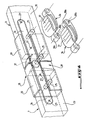
- FIG. 2 is a top elevational view of a part of a frame with articulated frames without slats transversal support of a user and showing the different transverse axes of support of the invention to the spars of these frames.
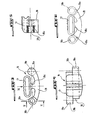
- FIG. 3 is a front view of a support endpiece of a lath according to the invention.
- FIG. 4 is a top view along arrow IV of FIG. the tip of Figure 3.
- FIG. 5 is a sectional view along line V-V of FIG. Figure 3.
- FIG. 6 represents the tip of FIG. 2 in one configuration corresponding to an applied load vertically on it by the corresponding slat.
- Figure 7 is an enlarged partial perspective view of the two frames of the liftable file part of the bed base and forming a double headrest.
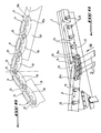
- Figure 8 is an enlarged perspective view of the part of the joint, at the knees of a user, between two adjacent spars respectively of the two articulated support frames of the user's legs.
- Figure 9 shows in perspective the two longitudinal members of the two articulated frames of Figure 8 in position identified.
- FIG. 10 is a front view along arrow X of the two raised spars of Figure 9 with the chain continuous slats support tips formed on these beams.
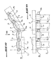
- Figure 11 is a partial perspective side view and enlarged representing the portion of a frame spar from the back of the articulated bed base to the corresponding section of chassis of it with two end pieces of the invention respectively of this frame and an adjacent fixed frame mounted in common on the axis of articulation of the spar of the part of the file.
- FIG. 12 is a front view along arrow XII of FIG. FIG. 10 and representing the continuous chain of end pieces of the invention mounted on the two longitudinal members of the frame of the backrest and fixed frame in the gluteal area.
- Figure 13 is a top view along arrow XIII of Figure 12.
- the bed frame shown is of the type comprising a chassis 1 in form frame members 2 and cross members 3, on which are articulated several liftable parts located from and other of a fixed part 4 corresponding to the zone buttocks of the user and including a part lift of file 5 on which can lean back and the user's head and two liftable parts articulated together 6, 7 corresponding to the legs of use.
- the lifting part of file 5 is constituted by a frame with longitudinal members 8 and cross members 9, each spar 8 having its end located towards the zone buttocks pivotally attached to spars or shanks 2 of the bed base on an axis of articulation 10 integral with the 2.
- liftable backrest 5 is actually carried out under a double headrest that can be telescopically lengthened in its longitudinal direction when lifting of Part 5 and which includes a first box 11 of support slats 12, two of which are only partially shown, provided with longitudinal members 8 articulated pivotally to the longitudinal members 2 of the bed base, a second support frame 13 for slats 12 with longitudinal members 8, mounted on the first frame 11 pivotally and telescopically mobile with respect to the latter during the lifting of the back portion 5.
- An arm mechanism swivels and links, generally referenced in 14 in FIG.
- the transverse slats 12 are supported between the rails 8 of the frames 11 and 13 of the part of backrest 5 by end caps 16 attached to the inner wall of each spar 8 and each comprising at least one cap-shaped portion 17, into which a corresponding end of a slat, attached to a body 18 of the endpiece 16 attached to the spar 8.
- the end pieces 16 are made from a material based on rubber or soft plastic material and are integrally molded.
- the two lifting parts 6, 7 of leg support each consist of a frame with longitudinal members 19 between which are supported slats (not shown), each spar 19 of the frame 6 having its end located near the fixed frame 4 hinged pivotally around a transverse axis 20 secured to the spar 2 of the sommier, while each spar 19 of the other frame 7 at its opposite end to the also articulated frame 6 of pivoting way around a transverse axis 21 secured of the spar 2.
- the slats of the frames 6, 7 are supported at their ends by end pieces 16 identical to end pieces 16 of FIG. 7 and fixed to the internal face of the longitudinal members 19 of these frames.
- the rails 22 of the fixed frame 4 are secured to the longitudinal members 2 of the bed base by fixing screws 23 and the slats (not shown) of this frame are also supported at their ends by end caps 16 attached to the inner face of each spar 22 and identical to the end pieces 16 of FIG.
- the frames 6, 7 can be raised or lowered by a mechanism with pivoting arms and links 24, known in self, and which does not have to be more detailed because not part of the invention.
- a motorized assembly (not shown) makes it possible to control the lifting mechanisms of Parts 5, 6 and 7 of sommier using a control box.
- the endpieces 16 are attached to the spar corresponding to each of the frames 4, 6, 7, 11 and 13 of way to form a continuous chain of bits spaced from equistently from each other along the spar, with chains of end pieces of spars on the same side different fixed and lifting frames located in a same longitudinal vertical plane.
- the body 18 of each endpiece 16 comprises two parallel opposite extreme mounting lugs 18a having each a transverse bore 18b so as to allow their commitment respectively on two support axes transverse 25 integral with the corresponding spar of the frame 4, 6, 7, 11 and 13 and on which is mounted the continuous chain of bits 16.
- the two legs of fixing 18a respectively of two successive tips 16 are mounted on a common transverse support axis 25 to form the continuous chain of bits.
- Figure 4 shows that the two brackets 18a of each endpiece 16 are offset laterally with respect to the other so that once the tips 16 fitted on their respective support pins 25 to form the chain continuous, their end-receiving parts 17 slats and their bodies 18 extend the same distance of the inner face of the corresponding spar of the frame 4, 6, 7, 11 or 13. Since the tips 16 are made of a rubber-based material, all of them are all simply mounted by hooking up their brackets 18a on the respective support pins 25 and these legs are held elastically and removably on the axes 25 without the need to provide for other means for preventing the tips 16 from escaping laterally of their support axes 25. The latter are of course fixed to the longitudinal members of the frames 4, 6, 7, 11 and 13 at equal distances therealong.
- the parts 17 for receiving the ends of the slats 12 are attached to their respective bodies 18 by feet 18c which are relatively rigid transversely for ensure slat stability in their directions longitudinal.
- the bodies 18 of the end pieces 16 are fixed to the corresponding spars so that their parts 17 of the ends of slats 12 are approximately the same level as the top edge of this spar and, preferably, the receiving parts 17 have their funds in the vicinity of the inner face the spar or in contact with it.
- Figures 4 and 5 show the hooded shape of each of the receiving parts 17 of the ends of the slats and having a cross section substantially rectangular shape conjugate to that of ends of the slats.
- Figure 6 shows a tip 16 whose receiving part 17 is supported by its edges on the body 18 by elastic deformation in compression of the foot 18c resulting from a vertical load applied by the corresponding end of a slat when a user is lying on the slats of the bedspring.
- each lateral chain of bits 16 can be assured between the two adjacent spars 19 respectively of the two frames articulated between them 6 and 7 at the knee level of a user.
- Figures 8 to 10 represent an achievement to ensure a such continuity of chain bits 16.
- the longitudinal members 19 of the two frames 6, 7 of the lifting part legs support are interconnected by two lateral joints in compass.
- Each articulation in compass comprises two arms 26, substantially shaped rectangular plate, respectively fixed to both sides internal verticals of the two adjacent spars 19 frames 6, 7 by fixing screws 27 or other means equivalent fasteners.
- the axis of articulation of the arms 26 of the compass is extended by a transverse axis 25 on which can engage two brackets 18a respectively of two consecutive ends 16.
- two adjacent end caps 16 mounted on the axis of articulation of the compass can follow, at the way of a caterpillar, the displacements of this articulation during lifting movements or lowering each pair of longitudinal members 19 of the frames articulated 6, 7.
- FIGS 8 and 9 also show that each pair of adjacent spars 19 of the frames 6, 7 is provided with a cache 28 intended to cover the occulting space free between the two ends vis-à-vis respectively of the two adjacent spars 19.
- This cache comprises two shells 29 mounted by interlocking respectively on both ends of the side members adjacent 19, one 29 of the shells comprising a male end portion 30 engaging in a portion female end 31 of the other shell 29, the shapes male and female end portions 31 of the shells 29 being arranged to allow the time the articulation between the two shells 29 and the constant occultation of the space between the longitudinal members 19 when raising or lowering these side members.
- FIGS 11 to 13 show the continuity of a chain of bits 16 between the spar 8 of the part frame lift of back 5 and the spar 22 of the fixed frame 4.
- each pivot axis 10 of the frame of the backrest is extended by a transverse support shaft 25 on which are engaged the two fixing lugs 18a respectively of two consecutive tips 16, one of which has its other fixing lug 18a engaged on the axis transverse end support 25 of the frame spar 22 4 and the other has its bracket 18a opposite to the pivot axis engaged on a support axis 25 of the spar 8 of the frame of the part of the backrest 5.
- the two extreme axes 25 of each spar 22 frame 4 extends respectively the two axes of fixing 23 of this spar to the spar 2 of the bed.
- the last tip 16 of each frame spar of the file part 5 located in the gluteal area can rotate around the axis 10 during the movement of raising or lowering of this frame.
- the game of automatically retractable folder 15 includes each side of the bed frame a plate 32 connected to the mechanism of pivoting 14 and having two transverse axes 25 solidary of its upper part on which are mounted the two fastening lugs 18a of a tip 16.
- Each support plate 32 of a tip 16 is located at near the spar 2 of the bed base so that the endpiece 16 that it supports is located in the same vertical plane longitudinal ends 16 secured to the longitudinal members 8 first and second frames 11, 13 of the forming part 5.
- the file part 15 occupies its position in the space between the first and second frames 11, 13 so that each tip 16 supported by the plate 32 is located between the two end caps respectively of the two longitudinal members 8 of these frames to ensure visually the continuity of each side chain continuous bits on these spars.
- the invention thus makes it possible to produce a continuous chain of tips over practically the entire length of each springboard spar so that the transverse slats are almost all located at equal distances each other.
- the design of the tips as well that, where appropriate, their fastening close to the face inside the corresponding spar of each frame, avoids the phenomenon of floating laths in their longitudinal directions.
- the assembly of the tips on their respective support axes is extremely easy and does not require any special tools and the replacing a defective tip can be easily performed even by the user of the bed base.
Landscapes
- Health & Medical Sciences (AREA)
- General Health & Medical Sciences (AREA)
- Nursing (AREA)
- Invalid Beds And Related Equipment (AREA)
- Bedding Items (AREA)
- Packaging Of Annular Or Rod-Shaped Articles, Wearing Apparel, Cassettes, Or The Like (AREA)
- Specific Sealing Or Ventilating Devices For Doors And Windows (AREA)
- Joining Of Corner Units Of Frames Or Wings (AREA)
- Chair Legs, Seat Parts, And Backrests (AREA)
- Slide Fasteners, Snap Fasteners, And Hook Fasteners (AREA)
Claims (18)
- Vorrichtung zum Befestigen der Querlatten (12) eines Lattenrostes, der ein Gestell (1) enthält, an dem zumindest zwei jeweilige anhebbare Teile der Rückenlehne (5) bzw. der Stütze (6, 7) für die Beine eines Benutzers angelenkt sind, die jeweils in Form eines Rahmens mit Latten (12) vorliegen, vom Typ mit Ansatzstücken (16) zum Tragen der Latten (12), die an jedem Längsträger des Rahmens eines jeden anhebbaren Teils (5, 6, 7) befestigt sind, wobei jedes Ansatzstück (16) einen Körper (18) zum Befestigen desselben am entsprechenden Längsträger und ein Aufnahmeteil (17) zum Aufnehmen des Endes einer Latte (12) enthält, wobei die Körper (18) der Ansatzstücke (16) am entsprechenden Längsträger so befestigt sind, dass sie eine kontinuierliche Kette von Ansatzstücken (16) bilden, die entlang des Längsträgers im gleichen Abstand voneinander vorgesehen sind, dadurch gekennzeichnet, dass der anhebbare Teil der Stütze der Beine zwei Rahmen (6, 7) enthält, die um eine quer verlaufende Gelenkachse aneinander angelenkt sind, die sich im Bereich der Knie des Benutzers befinden, und zwei aufeinanderfolgende Körper (18) der Ansatzstücke (16) einer jeden kontinuierlichen Kette zweier Längsträger der beiden Rahmen (6, 7) gemeinsam mit einer Tragquerachse (25) verbunden sind, welche die Gelenkachse verlängert, und zwar nach Art einer Raupe, so dass sie den Verlagerungen dieser Achse beim Anheben bzw. Absenken der beiden Rahmen (6, 7) folgen.
- Vorrichtung nach Anspruch 1, dadurch gekennzeichnet, dass die kontinuierlichen Ketten von Ansatzstücken (16) der Längsträger der Rahmen einer gleichen Seite in einer gleichen senkrechten Längsebene liegen.
- Vorrichtung nach Anspruch 1 oder 2, dadurch gekennzeichnet, dass jeder Ansatzstückkörper (18) zwei endseitige Befestigungslaschen (18a) enthält, die einander entgegengesetzt sind und zueinander parallel verlaufen und quer durchbohrt sind, so dass sie an jeweiligen Tragquerachsen (25) angreifen können, die fest mit dem entsprechenden Längsträger verbunden sind, wobei die beiden Befestigungslaschen (18a) von zwei jeweiligen Körpern (18) der aufeinanderfolgenden Ansatzstücke (16) an einer gemeinsamen Tragquerachse (25) angreifen, um die kontinuierliche Kette von Ansatzstücken zu bilden.
- Vorrichtung nach Anspruch 3, dadurch gekennzeichnet dass die Befestigungslaschen (18a) eines jeden Ansatzstückkörpers (18) seitlich zueinander versetzt sind, so dass bei Angreifen der Befestigungslaschen (18a) der Körper aufeinanderfolgender Ansatzstücke (16) einer kontinuierlichen Kette an ihren jeweiligen gemeinsamen Tragachsen (25) die Körper (18) der Ansatzstücke (16) und ihre Aufnahmeteile (17) zum Aufnehmen der Enden der Latten sich im gleichen Abstand von der Innenseite des entsprechenden Längsträgers erstrecken.
- Vorrichtung nach einem der Ansprüche 2 bis 4, dadurch gekennzeichnet, dass die Abstände zwischen den Bohrungen (18b) der Laschen (18a) der Ansatzstücke (16) gleich sind.
- Vorrichtung nach einem der vorangehenden Ansprüche, dadurch gekennzeichnet, dass die Aufnahmeteile (17) zum Aufnehmen der Latten (12) an ihren jeweiligen Körpern (18) mittels Füße (18c) befestigt sind, die in Querrichtung relativ starr sind und für eine Stabilität der Latten (12) in ihren Längsrichtungen sorgen.
- Vorrichtung nach Anspruch 6, dadurch gekennzeichnet, dass die Körper (18) der Ansatzstücke (16) am entsprechenden Längsträger so befestigt sind, dass ihre Aufnahmeteile (17) zum Aufnehmen der Enden der Latten (12) annähernd in der gleichen Höhe liegen wie der obere Rand dieses Längsträgers.
- Vorrichtung nach Anspruch 7, dadurch gekennzeichnet, dass die vorgenannten Aufnahmeteile (17) mit ihrem Boden benachbart zur Innenseite des Längsträgers vorgesehen oder in Kontakt mit dieser sind.
- Vorrichtung nach einem der Ansprüche 1 bis 8, dadurch gekennzeichnet, dass die Aufnahmeteile (17) zum Aufnehmen der Enden der Latten (12) jeweils in Form einer Kappe ausgebildet sind, die einen rechteckförmigen Querschnitt aufweist und quer zum entsprechenden Längsträger verläuft.
- Vorrichtung nach einem der Ansprüche 2 bis 9, dadurch gekennzeichnet, dass die beiden Rahmen (6, 7) des anhebbaren Teils zum Abstützen der Beine über zwei seitliche Zirkelgelenke miteinander verbunden sind, deren jeweilige Gelenkachse die Tragquerachse (25) enthält, die den beiden jeweiligen Befestigungslaschen (18a) der beiden Körper aufeinanderfolgender Ansatzstücke (16) gemein ist.
- Vorrichtung nach einem der Ansprüche 1 bis 10, dadurch gekennzeichnet, dass der Rahmen des anhebbaren Teils der Rückenlehne (5) an den Kanten (2) des Gestells (1) des Lattenrosts über zwei Querachsen (10) verschwenkbar angelenkt ist und dass zwei aufeinanderfolgende Körper der Ansatzstücke (16) einer jeden kontinuierlichen Kette des Längsträgers des Rahmens der Rückenlehne und eines angrenzenden Längsträgers des festen Rahmens (4), welcher mit dem Rahmen der Rückenlehne den Hüftbereich definiert, gemeinsam mit der entsprechenden Gelenkachse (10) des Rahmens der Rückenlehne so verbunden sind, das der Körper des Ansatzstücks (16), der dem Rahmen der Rückenlehne zugeordnet ist, bei Verlagerungen des Rahmens um die Achse (10) herum schwenken kann.
- Vorrichtung nach einem der Ansprüche 2 bis 11, dadurch gekennzeichnet, dass jede Gelenkachse (10) des Rahmens der Rückenlehne über eine Querachse (25) zum Abstützen der beiden Befestigungslaschen (18a) der beiden jeweiligen Körper (18) der aufeinanderfolgenden Ansatzstücke (16) verlängert ist, die dem Rahmen der Rückenlehne bzw. dem angrenzenden festen Rahmen (4) zugeordnet sind.
- Vorrichtung nach einem der Ansprüche 2 bis 12, dadurch gekennzeichnet, dass der anhebbare Rückenlehnenteil (5) in Form einer zweifachen Kopfstütze ausgeführt ist, die beim Anheben des Rückenlehnenteils (5) in ihrer Längsrichtung teleskopartig verlängert werden kann und einen ersten Rahmen (11) zum Abstützen der Latten (12) enthält, der mit Längsträgem (8) versehen ist, die mit einem Ende an den Kanten (2) des Gestells (1) des Lattenrosts verschwenkbar angelenkt sind, wobei eine kontinuierliche Kette von Ansatzstücken (16) zum Abstützen der Latten (12) an jedem Längsträger (8) des ersten Rahmens (11) befestigt ist, sowie einen zweiten Rahmen (13) zum Abstützen der Latten (12) mit Längsträgem (8), der am ersten Rahmen (11) bezüglich desselben beim Anheben des Rückenlehnenteils (5) verschwenkbar und teleskopartig verschiebbar montiert ist, wobei eine kontinuierliche Kette von Ansatzstücken (16) an jedem Längsträger (8) des zweiten Rahmens (13) befestigt ist, und dass ein einfahrbares Rückenlehnenteil (15) mit zumindest einer Latte (12) dazu vorgesehen ist, um automatisch den zwischen dem ersten und dem zweiten Rahmen (11, 13) bestehenden Raum einzunehmen, wenn das Rückenlehnenteil (5) angehoben wird, wobei die Latte (12) des einfahrbaren Teils (15) an jedem ihrer Enden von einer Seitenplatte (32) über ein Ansatzstück (16) mit Befestigungslaschen (18a) abgestützt wird, die an zwei Tragquerachsen (25) der Seitenplatte (32) montiert sind, die relativ zum Gestell des Lastenrosts so angeordnet ist, dass das Ansatzstück (16), das sie trägt, und die Ansatzstücke (16) der kontinuierlichen seitlichen Ketten des ersten bzw. des zweiten Rahmens (11, 13) in der gleichen senkrechten Längsebene liegen.
- Vorrichtung nach einem der vorangehenden Ansprüche, dadurch gekennzeichnet, dass jedes der aneinandergrenzenden Paare von Längsträgem der beiden jeweiligen angelenkten Rahmen (6, 7) des anhebbaren Teils zum Abstützen der Beine mit einer Blende (28) versehen ist, welche den Freiraum zwischen den beiden gegenüberliegenden Enden der beiden jeweiligen aneinandergrenzenden Längsträger (19) überdeckt.
- Vorrichtung nach Anspruch 14, dadurch gekennzeichnet, dass die Blende (28) zwei Schalen (29) enthält, die zueinander angelenkt sind und durch Aufstecken an den beiden jeweiligen Enden der Längsträger (19) befestigt sind, wobei die eine Schale (29) einen endseitigen Einsteckabschnitt (30) enthält, der in einen endseitigen Aufnahmeabschnitt (31) der anderen Schale (29) so eingreift, dass der Raum zwischen aneinandergrenzenden Längsträgem (19) beim Anheben bzw. Absenken der beiden Anlenkrahmen (6, 7) stets verdeckt ist.
- Vorrichtung nach einem der Ansprüche 2 bis 15, dadurch gekennzeichnet, dass die Ansatzstücke (16) aus einem Material auf Gummibasis oder aus weichem Kunststoff bestehen und jeweils abnehmbar an ihren jeweiligen Tragachsen (25) über ihre Befestigungslaschen (18a) montiert sind, die elastisch an diesen Achsen (25) angreifen.
- Vorrichtung zum Befestigen der Querlatten (12) eines Lattenrostes, der ein Gestell (1) enthält, an dem zumindest zwei anhebbare Teile der Rückenlehne (5) bzw. der Stütze (6, 7) für die Beine eines Benutzers angelenkt sind, die jeweils in Form eines Rahmens mit Latten (12) vorliegen, vom Typ mit Ansatzstücken (16) zum Tragen der Latten (12), die an jedem Längsträger des Rahmens eines jeden anhebbaren Teils (5, 6, 7) befestigt sind, wobei jedes Ansatzstück (16) einen Körper (18) zum Befestigen desselben am entsprechenden Längsträger und ein Aufnahmeteil (17) zum Aufnehmen des Endes einer Latte (12) enthält, wobei die Körper (18) der Ansatzstücke (16) am entsprechenden Längsträger so befestigt sind, dass sie eine kontinuierliche Kette von Ansatzstücken (16) bilden, die entlang des Längsträgers im gleichen Abstand voneinander vorgesehen sind, dadurch gekennzeichnet, dass der Rahmen des anhebbaren Teils der Rückenlehne (5) an den Kanten (2) des Gestells (1) des Lattenrosts über zwei Querachsen (10) verschwenkbar angelenkt ist und dass zwei aufeinanderfolgende Körper der Ansatzstücke (16) einer jeden kontinuierlichen Kette des Längsträgers des Rahmens der Rückenlehne und eines angrenzenden Längsträgers des festen Rahmens (4), welcher mit dem Rahmen der Rückenlehne den Hüftbereich definiert, gemeinsam mit einer Tragquerachse (25) verbunden sind, welche die entsprechende Gelenkachse (10) des Rahmens der Rückenlehne so verlängert, dass der Körper des Ansatzstücks (16), der dem Rahmen der Rückenlehne zugeordnet ist, bei Verlagerungen des Rahmens um die Tragachse (25) herum schwenken kann.
- Vorrichtung nach Anspruch 17, dadurch gekennzeichnet, dass jede Querachse (25), welche die entsprechende Gelenkachse (10) des Rahmens der Rückenlehne verlängert, zwei angrenzende Befestigungslaschen (18a) der beiden jeweiligen Körper (18) von aufeinanderfolgenden Ansatzstücken (16) trägt, die dem Rahmen der Rückenlehne bzw. dem angrenzenden festen Rahmen (4) zugeordnet sind.
Applications Claiming Priority (2)
| Application Number | Priority Date | Filing Date | Title |
|---|---|---|---|
| FR9709030 | 1997-07-16 | ||
| FR9709030A FR2766074B1 (fr) | 1997-07-16 | 1997-07-16 | Dispositif destine a la fixation de lattes transversales d'un sommier de literie |
Publications (3)
| Publication Number | Publication Date |
|---|---|
| EP0891732A2 EP0891732A2 (de) | 1999-01-20 |
| EP0891732A3 EP0891732A3 (de) | 2000-12-20 |
| EP0891732B1 true EP0891732B1 (de) | 2005-02-23 |
Family
ID=9509283
Family Applications (1)
| Application Number | Title | Priority Date | Filing Date |
|---|---|---|---|
| EP98401780A Expired - Lifetime EP0891732B1 (de) | 1997-07-16 | 1998-07-15 | Befestigungsvorrichtung für die Latten eines Lattenrostes |
Country Status (5)
| Country | Link |
|---|---|
| EP (1) | EP0891732B1 (de) |
| AT (1) | ATE289488T1 (de) |
| DE (1) | DE69829098T2 (de) |
| ES (1) | ES2238752T3 (de) |
| FR (1) | FR2766074B1 (de) |
Family Cites Families (4)
| Publication number | Priority date | Publication date | Assignee | Title |
|---|---|---|---|---|
| AT390722B (de) * | 1983-02-02 | 1990-06-25 | Wittmann Franz | Einsatz fuer ein liegemoebel |
| KR0141926B1 (ko) * | 1993-09-08 | 1999-02-18 | 기무라 겐지 | 침대의 바닥구조물 |
| DE4441476A1 (de) * | 1994-11-22 | 1996-05-23 | Erhard Dr Weber | Dreipunkt-Brückenfederungs-Endlager Triflex für Querleisten in Bettunterrahmen mit Verwendungen |
| DE29519946U1 (de) * | 1995-12-16 | 1996-02-15 | Schwenk, Hans Ulrich, Dipl.-Ing., 72766 Reutlingen | Gelenk für Lattenrost |
-
1997
- 1997-07-16 FR FR9709030A patent/FR2766074B1/fr not_active Expired - Fee Related
-
1998
- 1998-07-15 EP EP98401780A patent/EP0891732B1/de not_active Expired - Lifetime
- 1998-07-15 AT AT98401780T patent/ATE289488T1/de not_active IP Right Cessation
- 1998-07-15 DE DE69829098T patent/DE69829098T2/de not_active Expired - Lifetime
- 1998-07-15 ES ES98401780T patent/ES2238752T3/es not_active Expired - Lifetime
Also Published As
| Publication number | Publication date |
|---|---|
| EP0891732A2 (de) | 1999-01-20 |
| ATE289488T1 (de) | 2005-03-15 |
| DE69829098D1 (de) | 2005-03-31 |
| FR2766074B1 (fr) | 1999-10-08 |
| ES2238752T3 (es) | 2005-09-01 |
| FR2766074A1 (fr) | 1999-01-22 |
| EP0891732A3 (de) | 2000-12-20 |
| DE69829098T2 (de) | 2005-12-29 |
Similar Documents
| Publication | Publication Date | Title |
|---|---|---|
| EP2842803A1 (de) | Bett für Fahrzeug | |
| FR2647323A1 (fr) | Ensemble de lits superposes escamotables | |
| EP0761137B1 (de) | Lattenrost mit einem aufstellbaren und ausziehbaren Rückenabschnitt | |
| EP2117384B1 (de) | Verbesserungen an sitz- oder liegestrukturen mit körperstützvorrichtung mit belastungsselbstausgleich | |
| EP0891732B1 (de) | Befestigungsvorrichtung für die Latten eines Lattenrostes | |
| FR2719206A1 (fr) | Lit d'enfant. | |
| EP0451643A2 (de) | Kraftfahrzeugheber | |
| EP0300939A2 (de) | Vorrichtung zum Entfalten und Verstauen eines Betts oder dergleichen in eine Unterdecke | |
| EP1372433B1 (de) | Bett mit rückenlehne | |
| FR2671468A1 (fr) | Sommier a dossier relevable et matelas adapte. | |
| EP2392232A1 (de) | Sitz- oder Liegevorrichtung für Bettrahmen oder Sitzgestell | |
| EP0406044B1 (de) | Vorrichtung für eine Bettcouch | |
| GB2402616A (en) | A bed convertible between a bunk bed and a convertible bed | |
| FR2885504A1 (fr) | Lit de malade a barriere laterale complete | |
| FR2711521A1 (fr) | Lit pour malade. | |
| EP0895738B1 (de) | Verformbarer Bettboden mit geneigtem ergonomischen Ausschnitt | |
| FR3013953A1 (fr) | Dispositif de siege articule | |
| FR2672194A1 (fr) | Fauteuil a pietement en x, reglable notamment en inclinaison pour le dossier. | |
| EP1273248A1 (de) | Lattenrost mit variierbarer Festigkeit | |
| FR2957498A1 (fr) | Canape-lit converture, comportant un sommier pliable dont le deploiement est perfectionne | |
| CH663527A5 (fr) | Canape-lit. | |
| FR2464042A1 (fr) | Lit pliant d'ameublement transformable en canape | |
| FR2547184A3 (fr) | Siege ou fauteuil transformable en lit | |
| FR2828077A1 (fr) | Sommier de relaxation tpr | |
| EP0880922A2 (de) | Antikippvorrichtung für eine freitragende Matratzenstütze |
Legal Events
| Date | Code | Title | Description |
|---|---|---|---|
| PUAI | Public reference made under article 153(3) epc to a published international application that has entered the european phase |
Free format text: ORIGINAL CODE: 0009012 |
|
| AK | Designated contracting states |
Kind code of ref document: A2 Designated state(s): AT BE CH CY DE DK ES FI FR GB GR IE IT LI LU MC NL PT SE |
|
| AX | Request for extension of the european patent |
Free format text: AL;LT;LV;MK;RO;SI |
|
| PUAL | Search report despatched |
Free format text: ORIGINAL CODE: 0009013 |
|
| AK | Designated contracting states |
Kind code of ref document: A3 Designated state(s): AT BE CH CY DE DK ES FI FR GB GR IE IT LI LU MC NL PT SE |
|
| AX | Request for extension of the european patent |
Free format text: AL;LT;LV;MK;RO;SI |
|
| 17P | Request for examination filed |
Effective date: 20010619 |
|
| AKX | Designation fees paid |
Free format text: AT BE CH CY DE DK ES FI FR GB GR IE IT LI LU MC NL PT SE |
|
| 17Q | First examination report despatched |
Effective date: 20030428 |
|
| GRAP | Despatch of communication of intention to grant a patent |
Free format text: ORIGINAL CODE: EPIDOSNIGR1 |
|
| GRAS | Grant fee paid |
Free format text: ORIGINAL CODE: EPIDOSNIGR3 |
|
| GRAA | (expected) grant |
Free format text: ORIGINAL CODE: 0009210 |
|
| AK | Designated contracting states |
Kind code of ref document: B1 Designated state(s): AT BE CH CY DE DK ES FI FR GB GR IE IT LI LU MC NL PT SE |
|
| PG25 | Lapsed in a contracting state [announced via postgrant information from national office to epo] |
Ref country code: NL Free format text: LAPSE BECAUSE OF FAILURE TO SUBMIT A TRANSLATION OF THE DESCRIPTION OR TO PAY THE FEE WITHIN THE PRESCRIBED TIME-LIMIT Effective date: 20050223 Ref country code: IT Free format text: LAPSE BECAUSE OF FAILURE TO SUBMIT A TRANSLATION OF THE DESCRIPTION OR TO PAY THE FEE WITHIN THE PRE;WARNING: LAPSES OF ITALIAN PATENTS WITH EFFECTIVE DATE BEFORE 2007 MAY HAVE OCCURRED AT ANY TIME BEFORE 2007. THE CORRECT EFFECTIVE DATE MAY BE DIFFERENT FROM THE ONE RECORDED.SCRIBED TIME-LIMIT Effective date: 20050223 Ref country code: IE Free format text: LAPSE BECAUSE OF FAILURE TO SUBMIT A TRANSLATION OF THE DESCRIPTION OR TO PAY THE FEE WITHIN THE PRESCRIBED TIME-LIMIT Effective date: 20050223 Ref country code: FI Free format text: LAPSE BECAUSE OF FAILURE TO SUBMIT A TRANSLATION OF THE DESCRIPTION OR TO PAY THE FEE WITHIN THE PRESCRIBED TIME-LIMIT Effective date: 20050223 Ref country code: AT Free format text: LAPSE BECAUSE OF FAILURE TO SUBMIT A TRANSLATION OF THE DESCRIPTION OR TO PAY THE FEE WITHIN THE PRESCRIBED TIME-LIMIT Effective date: 20050223 |
|
| REG | Reference to a national code |
Ref country code: GB Ref legal event code: FG4D Free format text: NOT ENGLISH |
|
| REG | Reference to a national code |
Ref country code: CH Ref legal event code: EP |
|
| REG | Reference to a national code |
Ref country code: IE Ref legal event code: FG4D Free format text: FRENCH |
|
| REF | Corresponds to: |
Ref document number: 69829098 Country of ref document: DE Date of ref document: 20050331 Kind code of ref document: P |
|
| PG25 | Lapsed in a contracting state [announced via postgrant information from national office to epo] |
Ref country code: SE Free format text: LAPSE BECAUSE OF FAILURE TO SUBMIT A TRANSLATION OF THE DESCRIPTION OR TO PAY THE FEE WITHIN THE PRESCRIBED TIME-LIMIT Effective date: 20050523 Ref country code: GR Free format text: LAPSE BECAUSE OF FAILURE TO SUBMIT A TRANSLATION OF THE DESCRIPTION OR TO PAY THE FEE WITHIN THE PRESCRIBED TIME-LIMIT Effective date: 20050523 Ref country code: DK Free format text: LAPSE BECAUSE OF FAILURE TO SUBMIT A TRANSLATION OF THE DESCRIPTION OR TO PAY THE FEE WITHIN THE PRESCRIBED TIME-LIMIT Effective date: 20050523 |
|
| REG | Reference to a national code |
Ref country code: CH Ref legal event code: NV Representative=s name: TROESCH SCHEIDEGGER WERNER AG |
|
| GBT | Gb: translation of ep patent filed (gb section 77(6)(a)/1977) |
Effective date: 20050525 |
|
| PG25 | Lapsed in a contracting state [announced via postgrant information from national office to epo] |
Ref country code: CY Free format text: LAPSE BECAUSE OF FAILURE TO SUBMIT A TRANSLATION OF THE DESCRIPTION OR TO PAY THE FEE WITHIN THE PRESCRIBED TIME-LIMIT Effective date: 20050715 |
|
| PG25 | Lapsed in a contracting state [announced via postgrant information from national office to epo] |
Ref country code: MC Free format text: LAPSE BECAUSE OF NON-PAYMENT OF DUE FEES Effective date: 20050731 |
|
| NLV1 | Nl: lapsed or annulled due to failure to fulfill the requirements of art. 29p and 29m of the patents act | ||
| PG25 | Lapsed in a contracting state [announced via postgrant information from national office to epo] |
Ref country code: PT Free format text: LAPSE BECAUSE OF FAILURE TO SUBMIT A TRANSLATION OF THE DESCRIPTION OR TO PAY THE FEE WITHIN THE PRESCRIBED TIME-LIMIT Effective date: 20050803 |
|
| REG | Reference to a national code |
Ref country code: ES Ref legal event code: FG2A Ref document number: 2238752 Country of ref document: ES Kind code of ref document: T3 |
|
| REG | Reference to a national code |
Ref country code: IE Ref legal event code: FD4D |
|
| PLBE | No opposition filed within time limit |
Free format text: ORIGINAL CODE: 0009261 |
|
| STAA | Information on the status of an ep patent application or granted ep patent |
Free format text: STATUS: NO OPPOSITION FILED WITHIN TIME LIMIT |
|
| 26N | No opposition filed |
Effective date: 20051124 |
|
| PGFP | Annual fee paid to national office [announced via postgrant information from national office to epo] |
Ref country code: CH Payment date: 20110801 Year of fee payment: 14 |
|
| PGFP | Annual fee paid to national office [announced via postgrant information from national office to epo] |
Ref country code: LU Payment date: 20120727 Year of fee payment: 15 |
|
| PGFP | Annual fee paid to national office [announced via postgrant information from national office to epo] |
Ref country code: GB Payment date: 20120731 Year of fee payment: 15 |
|
| PGFP | Annual fee paid to national office [announced via postgrant information from national office to epo] |
Ref country code: ES Payment date: 20120829 Year of fee payment: 15 Ref country code: BE Payment date: 20120831 Year of fee payment: 15 |
|
| PGFP | Annual fee paid to national office [announced via postgrant information from national office to epo] |
Ref country code: DE Payment date: 20121001 Year of fee payment: 15 |
|
| PGFP | Annual fee paid to national office [announced via postgrant information from national office to epo] |
Ref country code: FR Payment date: 20130730 Year of fee payment: 16 |
|
| BERE | Be: lapsed |
Owner name: LA CIE CONTINENTALE *SIMMONS Effective date: 20130731 |
|
| REG | Reference to a national code |
Ref country code: CH Ref legal event code: PL |
|
| GBPC | Gb: european patent ceased through non-payment of renewal fee |
Effective date: 20130715 |
|
| PG25 | Lapsed in a contracting state [announced via postgrant information from national office to epo] |
Ref country code: CH Free format text: LAPSE BECAUSE OF NON-PAYMENT OF DUE FEES Effective date: 20130731 Ref country code: BE Free format text: LAPSE BECAUSE OF NON-PAYMENT OF DUE FEES Effective date: 20130731 Ref country code: GB Free format text: LAPSE BECAUSE OF NON-PAYMENT OF DUE FEES Effective date: 20130715 Ref country code: LI Free format text: LAPSE BECAUSE OF NON-PAYMENT OF DUE FEES Effective date: 20130731 Ref country code: DE Free format text: LAPSE BECAUSE OF NON-PAYMENT OF DUE FEES Effective date: 20140201 |
|
| REG | Reference to a national code |
Ref country code: DE Ref legal event code: R119 Ref document number: 69829098 Country of ref document: DE Effective date: 20140201 |
|
| PG25 | Lapsed in a contracting state [announced via postgrant information from national office to epo] |
Ref country code: ES Free format text: LAPSE BECAUSE OF NON-PAYMENT OF DUE FEES Effective date: 20130716 |
|
| REG | Reference to a national code |
Ref country code: FR Ref legal event code: ST Effective date: 20150331 |
|
| PG25 | Lapsed in a contracting state [announced via postgrant information from national office to epo] |
Ref country code: FR Free format text: LAPSE BECAUSE OF NON-PAYMENT OF DUE FEES Effective date: 20140731 |
|
| PG25 | Lapsed in a contracting state [announced via postgrant information from national office to epo] |
Ref country code: LU Free format text: LAPSE BECAUSE OF NON-PAYMENT OF DUE FEES Effective date: 20130715 |