EP0891818A2 - Installation de revêtement par poudrage avec pistolets pulvérisateurs alignés verticalement - Google Patents
Installation de revêtement par poudrage avec pistolets pulvérisateurs alignés verticalement Download PDFInfo
- Publication number
- EP0891818A2 EP0891818A2 EP98105877A EP98105877A EP0891818A2 EP 0891818 A2 EP0891818 A2 EP 0891818A2 EP 98105877 A EP98105877 A EP 98105877A EP 98105877 A EP98105877 A EP 98105877A EP 0891818 A2 EP0891818 A2 EP 0891818A2
- Authority
- EP
- European Patent Office
- Prior art keywords
- powder
- coating
- coating system
- devices
- flow
- Prior art date
- Legal status (The legal status is an assumption and is not a legal conclusion. Google has not performed a legal analysis and makes no representation as to the accuracy of the status listed.)
- Granted
Links
Images


Classifications
-
- B—PERFORMING OPERATIONS; TRANSPORTING
- B05—SPRAYING OR ATOMISING IN GENERAL; APPLYING FLUENT MATERIALS TO SURFACES, IN GENERAL
- B05B—SPRAYING APPARATUS; ATOMISING APPARATUS; NOZZLES
- B05B5/00—Electrostatic spraying apparatus; Spraying apparatus with means for charging the spray electrically; Apparatus for spraying liquids or other fluent materials by other electric means
-
- G—PHYSICS
- G01—MEASURING; TESTING
- G01F—MEASURING VOLUME, VOLUME FLOW, MASS FLOW OR LIQUID LEVEL; METERING BY VOLUME
- G01F1/00—Measuring the volume flow or mass flow of fluid or fluent solid material wherein the fluid passes through a meter in a continuous flow
- G01F1/56—Measuring the volume flow or mass flow of fluid or fluent solid material wherein the fluid passes through a meter in a continuous flow by using electric or magnetic effects
- G01F1/64—Measuring the volume flow or mass flow of fluid or fluent solid material wherein the fluid passes through a meter in a continuous flow by using electric or magnetic effects by measuring electrical currents passing through the fluid flow; measuring electrical potential generated by the fluid flow, e.g. by electrochemical, contact or friction effects
-
- B—PERFORMING OPERATIONS; TRANSPORTING
- B05—SPRAYING OR ATOMISING IN GENERAL; APPLYING FLUENT MATERIALS TO SURFACES, IN GENERAL
- B05B—SPRAYING APPARATUS; ATOMISING APPARATUS; NOZZLES
- B05B12/00—Arrangements for controlling delivery; Arrangements for controlling the spray area
- B05B12/004—Arrangements for controlling delivery; Arrangements for controlling the spray area comprising sensors for monitoring the delivery, e.g. by displaying the sensed value or generating an alarm
- B05B12/006—Pressure or flow rate sensors
-
- B—PERFORMING OPERATIONS; TRANSPORTING
- B05—SPRAYING OR ATOMISING IN GENERAL; APPLYING FLUENT MATERIALS TO SURFACES, IN GENERAL
- B05B—SPRAYING APPARATUS; ATOMISING APPARATUS; NOZZLES
- B05B12/00—Arrangements for controlling delivery; Arrangements for controlling the spray area
- B05B12/08—Arrangements for controlling delivery; Arrangements for controlling the spray area responsive to condition of liquid or other fluent material to be discharged, of ambient medium or of target ; responsive to condition of spray devices or of supply means, e.g. pipes, pumps or their drive means
- B05B12/085—Arrangements for controlling delivery; Arrangements for controlling the spray area responsive to condition of liquid or other fluent material to be discharged, of ambient medium or of target ; responsive to condition of spray devices or of supply means, e.g. pipes, pumps or their drive means responsive to flow or pressure of liquid or other fluent material to be discharged
-
- B—PERFORMING OPERATIONS; TRANSPORTING
- B05—SPRAYING OR ATOMISING IN GENERAL; APPLYING FLUENT MATERIALS TO SURFACES, IN GENERAL
- B05B—SPRAYING APPARATUS; ATOMISING APPARATUS; NOZZLES
- B05B13/00—Machines or plants for applying liquids or other fluent materials to surfaces of objects or other work by spraying, not covered by groups B05B1/00 - B05B11/00
- B05B13/02—Means for supporting work; Arrangement or mounting of spray heads; Adaptation or arrangement of means for feeding work
- B05B13/04—Means for supporting work; Arrangement or mounting of spray heads; Adaptation or arrangement of means for feeding work the spray heads being moved during spraying operation
- B05B13/0463—Installation or apparatus for applying liquid or other fluent material to moving work of indefinite length
- B05B13/0468—Installation or apparatus for applying liquid or other fluent material to moving work of indefinite length with reciprocating or oscillating spray heads
- B05B13/0473—Installation or apparatus for applying liquid or other fluent material to moving work of indefinite length with reciprocating or oscillating spray heads with spray heads reciprocating along a straight line
Definitions
- the invention relates to a powder coating system several coating devices, which are essentially vertical are arranged one above the other.
- the powder coating technology is related to the two points mentioned above are strongly developed and coating plants are also being built today, where the guns are vertically stacked, so that the one passing in the horizontal direction Workpiece only one gun at a time for coating one certain horizontal strip of the workpiece "responsible for.
- the advantage of this configuration is that the coating booth will be built much shorter can do what is readily understandable for the expert. Compare also Figs. 1 and 2, which later be explained in detail.
- the object of the present invention is therefore a powder coating system with several vertically one above the other Specify coating equipment where ensured is that the malfunction or failure of a coating machine not worsening overall Coating of the workpiece leads.
- This task is accomplished by using a powder coating system the features of claim 1 and by a method with the Features of claim 15 solved.
- the invention proposes a monitoring device which into the powder feed line of a coating device or into the coating device itself can be installed and a Signal delivers as soon as the flowing powder quantity below a predefinable target value falls or fails completely.
- a Signal delivers as soon as the flowing powder quantity below a predefinable target value falls or fails completely.
- the Powder coating system according to the invention and the method is the proper powder flow of each coating device monitored, and an alarm can be triggered as soon as little or no powder from the coater is delivered.
- the measurement signal which provides information about the amount of powder or the The presence of a powder stream can help with this different methods can be generated.
- the monitoring device can detect a tribo voltage, which of the powder flow in the powder path of a powder coating device is produced.
- a tribo voltage which of the powder flow in the powder path of a powder coating device is produced.
- the Driving nozzle of the powder feed injector or a powder feed to the coating device made of a material, which creates a tribo tension, or friction tension, as soon as powder particles are conveyed.
- the tribo tension is depending on the amount of powder conveyed; it transmits on the wall of the powder feed path and would normally dissipated to ground via a line.
- a metal housing for the injector a metal section in the powder channel of the coating device or one Metal section in the powder feed to the coating device can evaluate the tribo tension in a targeted manner become. If now e.g.
- the injector in a plastic holder insulated and into the line to ground Current meter is inserted can be due to the generated tribo voltage against mass flowing tribostream measure up.
- a signal can be obtained by measuring the tribostream which provides information about whether powder flows or not, and possibly how large the powder content in the Powder air flow is.
- a threshold can be defined be so that an alarm or the like is triggered when the tribostream falls below a preselected value.
- the mass of the powder contained in the powder stream in one Section of the powder path or the powder mass flow in the Powder path can be measured.
- Devices and Methods are used as they are in DE-A-44 06 046 and DE-A-196 50 112 are disclosed. To this Patent applications are expressly referred to here, and the devices and methods for measuring described there the speed of the powder flow, the density of the Powder flow and powder mass flow are by reference included in this application.
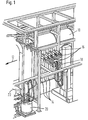
- FIG. 1 shows a conventional coating booth 10 Powder coating system, through which a to be coated Workpiece is transported through in the direction of arrow 12.
- a to be coated Workpiece is transported through in the direction of arrow 12.
- the workpiece (not shown) on one Transport rail hanging through the coating booth 10 emotional.
- vertical slots 14 are provided through which several in one horizontal guns 16 powder bring into the coating booth 10 and to the workpiece submit.
- the coating guns 16 are on an in vertically movable carriage 18 mounted, and while the workpiece in the direction of arrow 12 through the Coating cabin 10 is moved, the Coating guns 16 on the carriage 18 up and down to coat the workpiece evenly.
- a powder storage container 20 with the associated Air and powder lines and a control unit 22.
- Fig. 2 shows an electrostatic powder coating system according to the invention, in which the coating guns or Spray guns 24 are arranged vertically one above the other.
- the same Components as in Fig. 1 are given the same reference numerals referred to and not described again.
- the coating guns 24 are vertical on one Mounted movable frame 26; with a simplified Embodiment, however, they can also be fixed be.
- FIG. 3 shows a coating gun 24 with a powder supply line 30.
- a portion 32 of the powder feed line 30 is made of a material that has an electrical tribo voltage, or frictional tension generated once powder particles be promoted by line 30. This tribo tension now transfers to the metal sleeve 32 and would normally discharged via a ground line.
- the supply line 30 is not directly with ground connected, but via a current measuring device 34 to a Ground line 36 connected.
- the powder feed injector (not shown) in the powder coating gun 24 made of one material be produced, which is the electrical tribo voltage generated.
- the injector is e.g. in a Plastic bracket mounted insulated and over the Current meter 34 connected to the ground line 36.
- the tribo tension depends on the amount of the funded Powder; by measuring the tribostream can therefore be a Signal is obtained, which provides information about whether Powder flows or not, and possibly also over the Amount of powder transported.
- an additional, in the vertical direction on the frame 26 movably attached coating gun to the level of the failed or disturbed Coating gun drives and takes over its task.
Landscapes
- Chemical & Material Sciences (AREA)
- Physics & Mathematics (AREA)
- Analytical Chemistry (AREA)
- Fluid Mechanics (AREA)
- General Physics & Mathematics (AREA)
- Electrochemistry (AREA)
- Chemical Kinetics & Catalysis (AREA)
- Electrostatic Spraying Apparatus (AREA)
- Application Of Or Painting With Fluid Materials (AREA)
- Coating Apparatus (AREA)
- Spray Control Apparatus (AREA)
- Nozzles (AREA)
- Details Or Accessories Of Spraying Plant Or Apparatus (AREA)
Applications Claiming Priority (2)
| Application Number | Priority Date | Filing Date | Title |
|---|---|---|---|
| DE19717353 | 1997-04-24 | ||
| DE19717353A DE19717353A1 (de) | 1997-04-24 | 1997-04-24 | Pulverbeschichtungsanlage |
Publications (3)
| Publication Number | Publication Date |
|---|---|
| EP0891818A2 true EP0891818A2 (fr) | 1999-01-20 |
| EP0891818A3 EP0891818A3 (fr) | 2002-02-06 |
| EP0891818B1 EP0891818B1 (fr) | 2005-06-15 |
Family
ID=7827640
Family Applications (1)
| Application Number | Title | Priority Date | Filing Date |
|---|---|---|---|
| EP98105877A Expired - Lifetime EP0891818B1 (fr) | 1997-04-24 | 1998-03-31 | Installation de revêtement par poudrage avec pistolets pulvérisateurs alignés verticalement |
Country Status (8)
| Country | Link |
|---|---|
| US (1) | US6063195A (fr) |
| EP (1) | EP0891818B1 (fr) |
| JP (1) | JPH10309500A (fr) |
| KR (1) | KR19980081695A (fr) |
| CN (1) | CN1196979A (fr) |
| BR (1) | BR9801436A (fr) |
| DE (2) | DE19717353A1 (fr) |
| TW (1) | TW408040B (fr) |
Families Citing this family (11)
| Publication number | Priority date | Publication date | Assignee | Title |
|---|---|---|---|---|
| DE19819963A1 (de) * | 1998-05-05 | 1999-11-11 | Itw Gema Ag | Pulver-Sprühbeschichtungsvorrichtung |
| DE10111383B4 (de) * | 2001-03-09 | 2006-02-09 | Wagner International Ag | Verfahren zur Förderung von Beschichtungspulver zu einer Beschichtungseinheit und zugehörige Pulverfördervorrichtung |
| DE20107767U1 (de) * | 2001-05-08 | 2001-07-12 | Wagner International AG, Altstätten | Kabine zur Pulverbeschichtung von Werkstücken |
| US20030166311A1 (en) * | 2001-09-12 | 2003-09-04 | Seiko Epson Corporation | Method for patterning, method for forming film, patterning apparatus, film formation apparatus, electro-optic apparatus and method for manufacturing the same, electronic equipment, and electronic apparatus and method for manufacturing the same |
| JP3690380B2 (ja) * | 2002-08-02 | 2005-08-31 | セイコーエプソン株式会社 | 材料の配置方法、電子装置の製造方法、電気光学装置の製造方法 |
| WO2004060576A1 (fr) * | 2002-12-31 | 2004-07-22 | Truelove & Maclean, Incorporated | Procede de revetement de pieces metalliques etirees |
| WO2006023743A2 (fr) * | 2004-08-20 | 2006-03-02 | The Trustees Of Columbia University In The City Of New York | Dispositif epurateur laminaire permettant d'extraire le dioxyde de carbone de l'air et methode d'utilisation |
| US20120038346A1 (en) * | 2010-08-16 | 2012-02-16 | Nordson Corporation | Powder flow monitoring using grounded hoses |
| JP6724747B2 (ja) * | 2016-11-30 | 2020-07-15 | 東芝三菱電機産業システム株式会社 | 噴霧ノズル |
| CN107755116A (zh) * | 2017-11-11 | 2018-03-06 | 杨艳 | 一种可方便施工的喷尘机 |
| JP6993917B2 (ja) * | 2018-03-27 | 2022-01-14 | 本田技研工業株式会社 | 検査装置及び方法 |
Family Cites Families (16)
| Publication number | Priority date | Publication date | Assignee | Title |
|---|---|---|---|---|
| US3402697A (en) * | 1964-03-13 | 1968-09-24 | Devilbiss Co | Film thickness control for electrostatic coating systems |
| FR2442080A1 (fr) * | 1978-11-21 | 1980-06-20 | Europ Equip Menager | Installation de poudrage electrostatique d'objets |
| JPS58151517A (ja) * | 1982-03-05 | 1983-09-08 | Sumitomo Metal Ind Ltd | 粉粒体の流量測定方法及び装置 |
| DE3340510C2 (de) * | 1983-11-09 | 1986-10-30 | Hans-Josef 5010 Bergheim Licher | Elektrostatische Pulverbeschichtungsvorrichtung |
| US4714890A (en) * | 1984-10-09 | 1987-12-22 | Auburn International, Inc. | Flow measuring apparatus with analog, essentially linear output |
| DE3721875A1 (de) * | 1987-07-02 | 1989-01-12 | Gema Ransburg Ag | Verfahren und einrichtung fuer eine pulverspruehbeschichtungsanlage |
| US5060860A (en) * | 1989-08-18 | 1991-10-29 | Hughes Aircraft Company | Paint conductivity measurement system |
| JP2813007B2 (ja) * | 1989-10-11 | 1998-10-22 | バブコツク日立株式会社 | マイクロ波式粉体流量計 |
| JPH0498305A (ja) * | 1990-08-10 | 1992-03-31 | Fueroo Kogyo Kk | 粉・粒体制御システム |
| DE4406046C2 (de) * | 1994-02-24 | 1997-11-20 | Wagner Int | Einrichtung und Verfahren zum Messen eines Pulver-Massestromes |
| DE19524327A1 (de) * | 1994-10-24 | 1996-04-25 | Erich Kraemer | Pulverbeschichtungskabine |
| DE4443859A1 (de) * | 1994-12-09 | 1996-06-13 | Friedrich Lothar | Verfahren und Vorrichtung zum Messen der Lackierpulverdurchflußmengen bei der elektrostatischen Pulverbeschichtung |
| DE4444248A1 (de) * | 1994-12-13 | 1996-06-20 | Conrads Hans Georg Dipl Ing | Vorrichtung zur berührungsfreien Messung des Massedurchsatzes in Förderleitungen bei Zweiphasenströmungen mit Hilfe von Mikrowellen |
| DE19502741C2 (de) * | 1995-01-18 | 1997-04-03 | Alexander Ghantus | Einrichtung zur Erzeugung eines Stromes aus einem Pulver-Gas-Gemisch |
| US5739429A (en) * | 1995-07-13 | 1998-04-14 | Nordson Corporation | Powder coating system incorporating improved method and apparatus for monitoring flow rate of entrained particulate flow |
| DE19650112C1 (de) * | 1996-12-03 | 1998-05-20 | Wagner Int | Einrichtung und Verfahren zum Messen eines Pulver-Massestromes |
-
1997
- 1997-04-24 DE DE19717353A patent/DE19717353A1/de not_active Withdrawn
-
1998
- 1998-03-31 EP EP98105877A patent/EP0891818B1/fr not_active Expired - Lifetime
- 1998-03-31 DE DE59812864T patent/DE59812864D1/de not_active Expired - Fee Related
- 1998-04-22 JP JP10112063A patent/JPH10309500A/ja not_active Withdrawn
- 1998-04-23 US US09/065,761 patent/US6063195A/en not_active Expired - Fee Related
- 1998-04-23 BR BR9801436-6A patent/BR9801436A/pt not_active Application Discontinuation
- 1998-04-24 CN CN98107432A patent/CN1196979A/zh active Pending
- 1998-04-24 KR KR1019980014668A patent/KR19980081695A/ko not_active Abandoned
- 1998-04-30 TW TW087106371A patent/TW408040B/zh not_active IP Right Cessation
Also Published As
| Publication number | Publication date |
|---|---|
| KR19980081695A (ko) | 1998-11-25 |
| DE19717353A1 (de) | 1998-11-05 |
| TW408040B (en) | 2000-10-11 |
| EP0891818B1 (fr) | 2005-06-15 |
| JPH10309500A (ja) | 1998-11-24 |
| BR9801436A (pt) | 1999-11-03 |
| EP0891818A3 (fr) | 2002-02-06 |
| US6063195A (en) | 2000-05-16 |
| CN1196979A (zh) | 1998-10-28 |
| DE59812864D1 (de) | 2005-07-21 |
Similar Documents
| Publication | Publication Date | Title |
|---|---|---|
| DE69425023T2 (de) | Pulverbeschichtungssystem und Pulverbeschichtungsdicke-Sensor | |
| DE3325125C1 (de) | Anordnung zur Markierung von Fehlstellen an schnell laufenden Materialbahnen | |
| DE69430886T2 (de) | Verfahren und Vorrichtung zur Messung eines Pulvermassenstroms | |
| DE2750372C2 (de) | Verfahren zur elektrostatischen Beschichtung und Vorrichtung dazu | |
| DE4406046C2 (de) | Einrichtung und Verfahren zum Messen eines Pulver-Massestromes | |
| EP0891818B1 (fr) | Installation de revêtement par poudrage avec pistolets pulvérisateurs alignés verticalement | |
| DE102018131380A1 (de) | Reinigungsgerät für ein Applikationsgerät | |
| DE2812881B2 (de) | Vorrichtung zum Befeuchten und/oder Entladen elektrisch isolierender Gegenstände | |
| EP0913203B1 (fr) | Méthode et appareil de revêtement par poudre avec alimentation d'air de purge | |
| EP0780160B1 (fr) | Dispositif de revêtement de poudre par pulvérisation | |
| DE102009058208A1 (de) | Verfahren und Vorrichtung zum Abscheiden von Overspray sowie Anlage mit einer solchen | |
| EP0940189A2 (fr) | Intallation de revêtement par poudrage et procédé d'alimentation et de mélange de la poudre dans une telle installation | |
| DE19748376A1 (de) | Verfahren und Vorrichtung zum Pulver-Sprühbeschichten | |
| EP0899019B1 (fr) | Méthode de commande d'une installation de revêtement électrostatique dépendante de pièces et installation de revêtement électrostatique | |
| EP0069162A1 (fr) | Procédé et dispositif pour contrôler la répartition de densité dans une nappe de particules dispersée | |
| DE19738097C2 (de) | Verfahren zum Betreiben einer elektrostatischen Pulverbeschichtungsanlage und elektrostatische Pulverbeschichtungsanlage | |
| DE19847258B4 (de) | Verfahren und Vorrichtung zur Zustandserfassung von Beschichtungsmitteln beim elektrostatischen Beschichten von Gegenständen | |
| WO2000009338A1 (fr) | Procede et dispositif permettant de poudrer des feuilles imprimees | |
| DE102008047713B4 (de) | Verfahren und Vorrichtung zum Aufbringen von Puder auf einen bedruckten Bogen oder eine bedruckte Bahn | |
| DE3016458A1 (de) | Verfahren zum bestimmen und/oder steuern der beschichtungsstaerke von werkstuecken in beschichtungsanlagen, wie lackier-, pulverbeschichtungsanlagen o.dgl. und, vorrichtung zur durchfuehrung des verfahrens | |
| EP0438976A2 (fr) | Dispositif et procédé de contrôle du débit de poudre dans une installation de poudrage | |
| DE2605920C3 (de) | Verfahren und Vorrichtung zur elektrostatischen Bepulverung oder Befleckung | |
| DE19750862A1 (de) | Vorrichtung zum Nachweis viskoser Flüssigkeiten auf festem, insbesondere bewegtem Untergrund | |
| DE2427340A1 (de) | Regelung einer polymerbandherstellung | |
| DE3914360A1 (de) | Verfahren und vorrichtung zum verteilen von kleinteilen, wie glasbruchstuecken |
Legal Events
| Date | Code | Title | Description |
|---|---|---|---|
| PUAI | Public reference made under article 153(3) epc to a published international application that has entered the european phase |
Free format text: ORIGINAL CODE: 0009012 |
|
| AK | Designated contracting states |
Kind code of ref document: A2 Designated state(s): AT BE CH DE DK ES FI FR GB GR IE IT LI LU MC NL PT SE Kind code of ref document: A2 Designated state(s): CH DE FR IT LI |
|
| AX | Request for extension of the european patent |
Free format text: AL;LT;LV;MK;RO;SI |
|
| PUAL | Search report despatched |
Free format text: ORIGINAL CODE: 0009013 |
|
| AK | Designated contracting states |
Kind code of ref document: A3 Designated state(s): AT BE CH DE DK ES FI FR GB GR IE IT LI LU MC NL PT SE |
|
| AX | Request for extension of the european patent |
Free format text: AL;LT;LV;MK;RO;SI |
|
| RIC1 | Information provided on ipc code assigned before grant |
Free format text: 7B 05B 7/14 A, 7B 05B 12/08 B, 7G 01F 1/64 B |
|
| 17P | Request for examination filed |
Effective date: 20020719 |
|
| AKX | Designation fees paid |
Free format text: CH DE FR IT LI |
|
| 17Q | First examination report despatched |
Effective date: 20031006 |
|
| GRAP | Despatch of communication of intention to grant a patent |
Free format text: ORIGINAL CODE: EPIDOSNIGR1 |
|
| GRAS | Grant fee paid |
Free format text: ORIGINAL CODE: EPIDOSNIGR3 |
|
| GRAA | (expected) grant |
Free format text: ORIGINAL CODE: 0009210 |
|
| AK | Designated contracting states |
Kind code of ref document: B1 Designated state(s): CH DE FR IT LI |
|
| REG | Reference to a national code |
Ref country code: CH Ref legal event code: NV Representative=s name: ISLER & PEDRAZZINI AG Ref country code: CH Ref legal event code: EP |
|
| REF | Corresponds to: |
Ref document number: 59812864 Country of ref document: DE Date of ref document: 20050721 Kind code of ref document: P |
|
| ET | Fr: translation filed | ||
| PGFP | Annual fee paid to national office [announced via postgrant information from national office to epo] |
Ref country code: DE Payment date: 20060411 Year of fee payment: 9 |
|
| PLBE | No opposition filed within time limit |
Free format text: ORIGINAL CODE: 0009261 |
|
| STAA | Information on the status of an ep patent application or granted ep patent |
Free format text: STATUS: NO OPPOSITION FILED WITHIN TIME LIMIT |
|
| 26N | No opposition filed |
Effective date: 20060316 |
|
| REG | Reference to a national code |
Ref country code: CH Ref legal event code: PCAR Free format text: ISLER & PEDRAZZINI AG;POSTFACH 1772;8027 ZUERICH (CH) |
|
| PG25 | Lapsed in a contracting state [announced via postgrant information from national office to epo] |
Ref country code: DE Free format text: LAPSE BECAUSE OF NON-PAYMENT OF DUE FEES Effective date: 20071002 |
|
| PGFP | Annual fee paid to national office [announced via postgrant information from national office to epo] |
Ref country code: IT Payment date: 20120328 Year of fee payment: 15 |
|
| PGFP | Annual fee paid to national office [announced via postgrant information from national office to epo] |
Ref country code: FR Payment date: 20130325 Year of fee payment: 16 Ref country code: CH Payment date: 20130312 Year of fee payment: 16 |
|
| REG | Reference to a national code |
Ref country code: CH Ref legal event code: PL |
|
| REG | Reference to a national code |
Ref country code: FR Ref legal event code: ST Effective date: 20141128 |
|
| PG25 | Lapsed in a contracting state [announced via postgrant information from national office to epo] |
Ref country code: LI Free format text: LAPSE BECAUSE OF NON-PAYMENT OF DUE FEES Effective date: 20140331 Ref country code: FR Free format text: LAPSE BECAUSE OF NON-PAYMENT OF DUE FEES Effective date: 20140331 Ref country code: CH Free format text: LAPSE BECAUSE OF NON-PAYMENT OF DUE FEES Effective date: 20140331 |
|
| PG25 | Lapsed in a contracting state [announced via postgrant information from national office to epo] |
Ref country code: IT Free format text: LAPSE BECAUSE OF NON-PAYMENT OF DUE FEES Effective date: 20140331 |