EP0891855A2 - Method and apparatus for manufacturing of hollow plastic containers - Google Patents
Method and apparatus for manufacturing of hollow plastic containers Download PDFInfo
- Publication number
- EP0891855A2 EP0891855A2 EP98890161A EP98890161A EP0891855A2 EP 0891855 A2 EP0891855 A2 EP 0891855A2 EP 98890161 A EP98890161 A EP 98890161A EP 98890161 A EP98890161 A EP 98890161A EP 0891855 A2 EP0891855 A2 EP 0891855A2
- Authority
- EP
- European Patent Office
- Prior art keywords
- pressure level
- pressure
- blowing medium
- blank
- reduced
- Prior art date
- Legal status (The legal status is an assumption and is not a legal conclusion. Google has not performed a legal analysis and makes no representation as to the accuracy of the status listed.)
- Granted
Links
Images
Classifications
-
- B—PERFORMING OPERATIONS; TRANSPORTING
- B29—WORKING OF PLASTICS; WORKING OF SUBSTANCES IN A PLASTIC STATE IN GENERAL
- B29C—SHAPING OR JOINING OF PLASTICS; SHAPING OF MATERIAL IN A PLASTIC STATE, NOT OTHERWISE PROVIDED FOR; AFTER-TREATMENT OF THE SHAPED PRODUCTS, e.g. REPAIRING
- B29C49/00—Blow-moulding, i.e. blowing a preform or parison to a desired shape within a mould; Apparatus therefor
- B29C49/42—Component parts, details or accessories; Auxiliary operations
- B29C49/78—Measuring, controlling or regulating
- B29C49/783—Measuring, controlling or regulating blowing pressure
-
- B—PERFORMING OPERATIONS; TRANSPORTING
- B29—WORKING OF PLASTICS; WORKING OF SUBSTANCES IN A PLASTIC STATE IN GENERAL
- B29C—SHAPING OR JOINING OF PLASTICS; SHAPING OF MATERIAL IN A PLASTIC STATE, NOT OTHERWISE PROVIDED FOR; AFTER-TREATMENT OF THE SHAPED PRODUCTS, e.g. REPAIRING
- B29C49/00—Blow-moulding, i.e. blowing a preform or parison to a desired shape within a mould; Apparatus therefor
- B29C49/42—Component parts, details or accessories; Auxiliary operations
- B29C49/78—Measuring, controlling or regulating
- B29C49/783—Measuring, controlling or regulating blowing pressure
- B29C2049/7832—Blowing with two or more pressure levels
-
- B—PERFORMING OPERATIONS; TRANSPORTING
- B29—WORKING OF PLASTICS; WORKING OF SUBSTANCES IN A PLASTIC STATE IN GENERAL
- B29C—SHAPING OR JOINING OF PLASTICS; SHAPING OF MATERIAL IN A PLASTIC STATE, NOT OTHERWISE PROVIDED FOR; AFTER-TREATMENT OF THE SHAPED PRODUCTS, e.g. REPAIRING
- B29C2949/00—Indexing scheme relating to blow-moulding
- B29C2949/07—Preforms or parisons characterised by their configuration
- B29C2949/0715—Preforms or parisons characterised by their configuration the preform having one end closed
-
- B—PERFORMING OPERATIONS; TRANSPORTING
- B29—WORKING OF PLASTICS; WORKING OF SUBSTANCES IN A PLASTIC STATE IN GENERAL
- B29C—SHAPING OR JOINING OF PLASTICS; SHAPING OF MATERIAL IN A PLASTIC STATE, NOT OTHERWISE PROVIDED FOR; AFTER-TREATMENT OF THE SHAPED PRODUCTS, e.g. REPAIRING
- B29C49/00—Blow-moulding, i.e. blowing a preform or parison to a desired shape within a mould; Apparatus therefor
- B29C49/02—Combined blow-moulding and manufacture of the preform or the parison
- B29C49/06—Injection blow-moulding
-
- B—PERFORMING OPERATIONS; TRANSPORTING
- B29—WORKING OF PLASTICS; WORKING OF SUBSTANCES IN A PLASTIC STATE IN GENERAL
- B29K—INDEXING SCHEME ASSOCIATED WITH SUBCLASSES B29B, B29C OR B29D, RELATING TO MOULDING MATERIALS OR TO MATERIALS FOR MOULDS, REINFORCEMENTS, FILLERS OR PREFORMED PARTS, e.g. INSERTS
- B29K2067/00—Use of polyesters or derivatives thereof, as moulding material
Definitions
- the invention relates to a method for producing hollow containers of plastic, in particular of plastic bottles made of PET, where a preformed blank is placed in a blow mold and initially by means of a movable lance with introduction of a gaseous blowing medium with a first, lower pressure level is elongated, after which the container under Introduction of a gaseous blowing medium with a second, higher pressure level is finished. Furthermore, the invention also relates to one Device for producing hollow plastic containers, in particular of plastic bottles made of PET, with a blow mold and a longitudinally displaceable one Lance, which can be controlled via pressure lines in valves Sequence with gaseous blowing medium with two different ones Pressure levels can be connected.
- the object of the present invention is the method and device of the to improve the type mentioned so that the disadvantages of State of the art can be avoided and in particular as possible simple way to increase the speed of work or shorten the Cycle time in the manufacture of plastic bottles can be achieved.
- This object is achieved according to the present invention in a method of the type mentioned in that the blowing medium with the first Pressure level of the same pressure source as the blowing medium with the second one Pressure level is taken, with the air volume for the lower pressure level of the higher pressure level is reduced so far by throttling that due to the expansion in the elongated blank, the higher second pressure level is reduced to the lower first pressure level.
- the corresponding Embodiment of the device according to the invention is that a only common pressure source is provided for both pressure levels, wherein for the lower pressure level the air volume of the higher pressure level by means of a throttle switched into the associated pressure line is reduced so far is that the expansion in the elongated blank the higher second pressure level is reduced to the lower first pressure level.
- the device can be considerably simplified Way to a separate low pressure source (typically 10 to 12 bar).
- the amount of air from the high pressure source is used for the initial low-pressure stretching or longitudinal stretching over a throttle so far reduced that by expanding into the bottle during the initial Longitudinal expansion the high pressure level to the lower pressure level necessary is reduced.
- the method described does not mean just one Reduction of the cycle time (due to the elimination of a certain one Time-consuming switching between different pressure levels) but it can also be used on additional facilities otherwise required to be dispensed with.
- the throttle is adjustable to show the lower pressure level, with different requirements or environmental conditions or the like Can be taken into account.
- valves for control the sequence of the pressure levels of the blowing medium from pressure-balanced, quick-switching 2/2-way seat valves are formed, which optimized the reduction of the cycle time or increase of the working speed can be.
- Valves and preferably also the throttle, together with connecting lines in one common housing, preferably in the immediate vicinity of the blow mold, arranged are. This simplifies the construction further, for as much as possible low volume in the connecting lines and thus another Possibility to reduce cycle times.
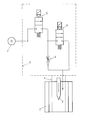
- Blank 1 is denoted by 2 and is usually not detailed in one here shown device for the simultaneous production of several plastic bottles built in, which also other not of interest here Parts includes.
- Blank 1 is inserted into the blow mold 2 by the blow molding method and initially stretched longitudinally by means of a movable lance 3 (in the illustration stretched downwards) being this longitudinal expansion by initiation a gaseous blowing medium with a first, lower pressure level is supported. Only then is the container created from the blank 1 introducing a gaseous blowing medium with a second, higher Pressure level molded.
- the blowing medium with the first pressure level is the same here, with D designated pressure source such as the blowing medium with the second, higher pressure level taken, the air volume of the higher pressure levels through throttling via an adjustable throttle 4 so is greatly reduced that by expanding into the elongated blank 1 the higher second pressure level is reduced to the lower first pressure level becomes.
- the pressure source D here provides pressure medium with a second, higher one Pressure level corresponding level of, for example, 40 bar is available.
- first pressure level approximately 10 to 12 bar
- this is spring-loaded in the closed position shown standing valve 5 brought into the open position, not shown, with what the air volume of the higher pressure level by throttling the Throttle 4 is reduced to such an extent that expansion into the blank 1 the higher pressure level (e.g. 40 bar) of pressure source D to the lower, first pressure level (e.g. 12 bar) is reduced.
- the two valves 5, 6 are preferably pressure-balanced, quick-switching 2/2-way seat valves formed and together with the throttle 4 in a dashed common housing 7 in the immediate vicinity the blow mold 2 arranged, with the described advantages of the arrangement still be supported.
Landscapes
- Engineering & Computer Science (AREA)
- Manufacturing & Machinery (AREA)
- Mechanical Engineering (AREA)
- Blow-Moulding Or Thermoforming Of Plastics Or The Like (AREA)
- Processing And Handling Of Plastics And Other Materials For Molding In General (AREA)
Abstract
Zur Herstellung von hohlen Behältern aus Kunststoff wird ein vorgeformter Rohling (1) in eine Blasform (2) eingelegt, mittels einer beweglichen Lanze (3) unter Einleitung eines Blasmediums längsgedehnt und sodann unter Einleitung eines Blasmediums mit höherem Druckniveau fertig geformt. Zur Verringerung der Umschaltzeiten zwischen den beiden üblichen Druckniveaus und damit zur Verkürzung der Herstellungszeit der Behälter wird das Blasmedium mit dem ersten, niedrigeren Druckniveau der gleichen Druckquelle (D) wie das Blasmedium mit dem zweiten, höheren Druckniveau entnommen, wobei für das niedrigere Druckniveau die Luftmenge des höheren Druckniveaus durch Drosselung so weit reduziert wird, daß durch die Expansion in den Rohling (1) das höhere zweite Druckniveau auf das niedrigere erste Druckniveau reduziert wird.For the production of hollow plastic containers, a preformed blank (1) is placed in a blow mold (2), stretched lengthwise by means of a movable lance (3) with the introduction of a blowing medium and then finally molded with the introduction of a blowing medium with a higher pressure level. To reduce the changeover times between the two usual pressure levels and thus to shorten the manufacturing time of the containers, the blowing medium with the first, lower pressure level is taken from the same pressure source (D) as the blowing medium with the second, higher pressure level, the air quantity being used for the lower pressure level of the higher pressure level is reduced by throttling so much that the expansion into the blank (1) reduces the higher second pressure level to the lower first pressure level.
Description
Die Erfindung betrifft ein Verfahren zur Herstellung von hohlen Behältern aus Kunststoff, insbesonders von Kunststoffflaschen aus PET, wobei ein vorgeformter Rohling in eine Blasform eingelegt und vorerst mittels einer beweglichen Lanze unter Einleitung eines gasförmigen Blasmediums mit einem ersten, niedrigeren Druckniveau längsgedehnt wird, wonach der Behälter unter Einleitung eines gasförmigen Blasmediums mit einem zweiten, höheren Druckniveau fertig geformt wird. Weiters betrifft die Erfindung aber auch eine Vorrichtung zur Herstellen von hohlen Behältern aus Kunststoff, insbesonders von Kunststoffflaschen aus PET, mit einer Blasform und einer darin längsverschieblichen Lanze, welche über Druckleitungen in mittels Ventilen steuerbarer Aufeinanderfolge mit gasförmigem Blasmedium mit zwei unterschiedlichen Druckniveaus verbindbar ist.The invention relates to a method for producing hollow containers of plastic, in particular of plastic bottles made of PET, where a preformed blank is placed in a blow mold and initially by means of a movable lance with introduction of a gaseous blowing medium with a first, lower pressure level is elongated, after which the container under Introduction of a gaseous blowing medium with a second, higher pressure level is finished. Furthermore, the invention also relates to one Device for producing hollow plastic containers, in particular of plastic bottles made of PET, with a blow mold and a longitudinally displaceable one Lance, which can be controlled via pressure lines in valves Sequence with gaseous blowing medium with two different ones Pressure levels can be connected.
Bei bekannten Verfahren und Vorrichtungen der eingangs genannten Art zur Herstellung von Kunststoffflaschen ist es heutzutage üblich, einen vorgeformten bzw. vorgespritzten Rohling in die Blasform einzulegen, wonach mittels einer Lanze dieser Rohling in die Länge gedehnt wird, wobei diese Dehnung von einem unter niedrigerem Druck (etwa 10 bis 12 bar) eingeleiteten Blasmedium unterstützt wird. Sobald diese Längendehnung zumindest im wesentlichen abgeschlossen ist, wird auf Hochdruck-Blasmedium (ca. 40 bar) umgeschaltet und die jeweilige Flasche in der Blasform fertig ausgebildet. Dieser hohe Druck muß dann kurze Zeit gehalten werden, damit die gedehnte Kunststoffflasche auf Dauer ihre Form behält.In known methods and devices of the type mentioned Nowadays, manufacturing plastic bottles it is common to have a preformed one or pre-injected blank into the blow mold, after which by means of a lance this blank is stretched in length, this Elongation from one initiated at lower pressure (about 10 to 12 bar) Blowing medium is supported. Once this elongation is at least essentially is switched to high pressure blowing medium (approx. 40 bar) and the respective bottle is finished in the blow mold. This high pressure must then be held for a short time so that the stretched plastic bottle keeps its shape in the long run.
Als Nachteil der bekannten Vorrichtungen und Verfahren der genannten Art ist zu erwähnen, daß der Herstellungszyklus für eine einzelne Kunststoffflasche größenordnungsmäßig etwa vier bis fünf Sekunden dauert, wobei aber 10% dieser Zeit alleine für das Umschalten vom niedrigeren Druckniveau des Blasmediums beim Längsdehnen auf das höhere Druckniveau beim Fertigformen entfällt. Diese vorrichtungs- bzw. verfahrensmäßig bedingte Totzeit behindert natürlich von vornherein die an sich im Zusammenhang mit der Herstellung derartiger Massenartikel angestrebte Erhöhung der Arbeitsgeschwindigkeit.As a disadvantage of the known devices and methods of the above Art is worth mentioning that the manufacturing cycle for a single plastic bottle of the order of magnitude takes about four to five seconds, although 10% of this time alone for switching from the lower pressure level of the Blowing medium when stretching longitudinally to the higher pressure level when finished molding not applicable. This device-related or procedural dead time is hampered from the outset, of course, in connection with the manufacture Such a mass article aimed at increasing the speed of work.
Aufgabe der vorliegenden Erfindung ist es, Verfahren und Vorrichtung der eingangs genannten Art so zu verbessern, daß die beschriebenen Nachteile des Standes der Technik vermieden werden und daß insbesonders auf möglichst einfache Weise eine Erhöhung der Arbeitsgeschwindigkeit bzw. Verkürzung der Taktzeit bei der Herstellung der Kunststoffflaschen erreicht werden kann.The object of the present invention is the method and device of the to improve the type mentioned so that the disadvantages of State of the art can be avoided and in particular as possible simple way to increase the speed of work or shorten the Cycle time in the manufacture of plastic bottles can be achieved.
Diese Aufgabe wird gemäß der vorliegenden Erfindung bei einem Verfahren der eingangs genannten Art dadurch gelöst, daß das Blasmedium mit dem ersten Druckniveau der gleichen Druckquelle wie das Blasmedium mit dem zweiten Druckniveau entnommen wird, wobei für das niedrigere Druckniveau die Luftmenge des höheren Druckniveaus durch Drosselung so weit reduziert wird, daß durch die Expansion in den längsgedehnten Rohling das höhere zweite Druckniveau auf das niedrigere erste Druckniveau reduziert wird. Die entsprechende Ausgestaltung der erfindungsgemäßen Vorrichtung besteht darin, daß eine einzige gemeinsame Druckquelle für beide Druckniveaus vorgesehen ist, wobei für das niedrigere Druckniveau die Luftmenge des höheren Druckniveaus mittels einer in die zugehörige Druckleitung eingeschalteten Drossel so weit reduziert wird, daß durch die Expansion in den längsgedehnten Rohling das höhere zweite Druckniveau auf das niedrigere erste Druckniveau reduziert wird.This object is achieved according to the present invention in a method of the type mentioned in that the blowing medium with the first Pressure level of the same pressure source as the blowing medium with the second one Pressure level is taken, with the air volume for the lower pressure level of the higher pressure level is reduced so far by throttling that due to the expansion in the elongated blank, the higher second pressure level is reduced to the lower first pressure level. The corresponding Embodiment of the device according to the invention is that a only common pressure source is provided for both pressure levels, wherein for the lower pressure level the air volume of the higher pressure level by means of a throttle switched into the associated pressure line is reduced so far is that the expansion in the elongated blank the higher second pressure level is reduced to the lower first pressure level.
Dadurch, daß nun die beschriebene Druckunterstützung bei der anfänglichen Längsdehnung des Rohlings ebenfalls der Hochdruckquelle (typischerweise 40 bar) entnommen wird, kann man in die Vorrichtung erheblich vereinfachender Weise auf eine separate Niederdruckquelle (typischerweise 10 bis 12 bar) verzichten. Die Luftmenge aus der Hochdruckquelle wird für die anfängliche Niederdruck-Streckung bzw. Längsdehnung über eine Drossel so weit reduziert, daß durch Expansion in die Flasche während der anfänglichen Längsdehnung das Hochdruck-Niveau auf das notwendigere geringere Druckniveau reduziert wird. Nachdem normalerweise bei entsprechenden Anordnungen ohnedies einstellbare Drossel für den Ausgleich beispielsweise von Temperatureinflüssen vorhanden sind, bedeutet die beschriebene Methode nicht nur eine Reduzierung der Zykluszeit (durch den Wegfall des auf alle Fälle eine gewisse Zeit in Anspruch nehmenden Umschaltens zwischen verschiedenen Druckniveaus) sondern es kann auch auf sonst erforderlichen zusätzliche Einrichtungen verzichtet werden.The fact that the pressure support described in the initial Elongation of the blank also the high pressure source (typically 40 bar) is removed, the device can be considerably simplified Way to a separate low pressure source (typically 10 to 12 bar). The amount of air from the high pressure source is used for the initial low-pressure stretching or longitudinal stretching over a throttle so far reduced that by expanding into the bottle during the initial Longitudinal expansion the high pressure level to the lower pressure level necessary is reduced. Normally with appropriate arrangements anyway adjustable throttle for compensation of temperature influences, for example the method described does not mean just one Reduction of the cycle time (due to the elimination of a certain one Time-consuming switching between different pressure levels) but it can also be used on additional facilities otherwise required to be dispensed with.
Gemäß einer bevorzugten Ausgestaltung der Erfindung ist vorgesehen, daß die Drossel zur Darstellung des niedrigeren Druckniveaus einstellbar ist, womit verschiedenen Anforderungen bzw. Umgebungsbedingungen oder dergleichen Rechnung getragen werden kann.According to a preferred embodiment of the invention it is provided that the throttle is adjustable to show the lower pressure level, with different requirements or environmental conditions or the like Can be taken into account.
In einer besonders bevorzugten Ausgestaltung der erfindungsgemäßen Vorrichtung kann schließlich vorgesehen sein, daß die Ventile zur Steuerung der Aufeinanderfolge der Druckniveaus des Blasmediums von druckausgeglichenen, schnellschaltenden 2/2-Wege-Sitzventilen gebildet sind, wodurch die Reduzierung der Taktzeit bzw. Erhöhung der Arbeitsgeschwindigkeit optimiert werden kann.In a particularly preferred embodiment of the invention Finally, device can be provided that the valves for control the sequence of the pressure levels of the blowing medium from pressure-balanced, quick-switching 2/2-way seat valves are formed, which optimized the reduction of the cycle time or increase of the working speed can be.
In weiterer Ausgestaltung der Erfindung kann vorgesehen sein, daß die Ventile und vorzugsweise auch die Drossel, samt Verbindungsleitungen in einem gemeinsamen Gehäuse, vorzugsweise in unmittelbarer Nähe der Blasform, angeordnet sind. Damit ist die Konstruktion weiter vereinfacht, für möglichst geringes Volumen in den Verbindunsleitungen gesorgt und damit eine weitere Möglichkeit zur Verringerung der Taktzeiten gegeben.In a further embodiment of the invention it can be provided that the Valves and preferably also the throttle, together with connecting lines in one common housing, preferably in the immediate vicinity of the blow mold, arranged are. This simplifies the construction further, for as much as possible low volume in the connecting lines and thus another Possibility to reduce cycle times.
Die Erfindung wird im folgenden noch anhand des in der Zeichnung schematisch dargestellten Ausführungsbeispiels einer entsprechenden Vorrichtung näher erläutert.The invention is illustrated schematically below with reference to the drawing illustrated embodiment of a corresponding device explained in more detail.
Die Blasform für den nur strichliert eingezeichneten, vorgeformten
Rohling 1 ist mit 2 bezeichnet und üblicherweise in einer hier nicht näher
dargestellten Vorrichtung für die gleichzeitige Herstellung mehrer Kunststoffflaschen
eingebaut, welche auch sonstige hier nicht interessierende
Teile umfaßt. Zur Herstellung beispielsweise von PET-Flaschen nach der
Blasformmethode wird der vorgefertigte Rohling 1 in die Blasform 2 eingelegt
und vorerst mittels einer beweglichen Lanze 3 längsgedehnt (in der Darstellung
nach unten gestreckt) wobei diese Längsdehnung durch Einleitung
eines gasförmigen Blasmediums mit einem ersten, niedrigeren Druckniveau
unterstützt wird. Erst danach wird der aus dem Rohling 1 entstehende Behälter
unter Einleitung eines gasförmigen Blasmediums mit einem zweiten, höheren
Druckniveau fertiggeformt.The blow mold for the pre-shaped one, which is only shown in broken lines
Blank 1 is denoted by 2 and is usually not detailed in one here
shown device for the simultaneous production of several plastic bottles
built in, which also other not of interest here
Parts includes. For the production of, for example, PET bottles
The prefabricated blank 1 is inserted into the
Das Blasmedium mit dem ersten Druckniveau wird hier der gleichen, mit D bezeichneten Druckquelle wie das Blasmedium mit dem zweiten, höheren Druckniveau entnommen, wobei für das niedrigere Druckniveau die Luftmenge des höheren Druckniveaus durch Drosselung über eine einstellbare Drossel 4 so weit reduziert wird, daß durch die Expansion in den längsgedehnten Rohling 1 das höhere zweite Druckniveau auf das niedrigere erste Druckniveau reduziert wird.The blowing medium with the first pressure level is the same here, with D designated pressure source such as the blowing medium with the second, higher pressure level taken, the air volume of the higher pressure levels through throttling via an adjustable throttle 4 so is greatly reduced that by expanding into the elongated blank 1 the higher second pressure level is reduced to the lower first pressure level becomes.
Die Druckquelle D stellt hier Druckmedium mit einem dem zweiten, höheren
Druckniveau entsprechenden Niveau von beispielsweise 40 bar zur Verfügung.
Für die Einleitung des niedrigeren, ersten Druckniveaus (etwa 10 bis 12 bar)
in den Rohling 1 wird das federbelastet in der dargestellten Schließstellung
stehende Ventil 5 in die nicht dargestellte Durchlaßstellung gebracht, womit
die Luftmenge des an sich höheren Druckniveaus durch Drosselung über die
Drossel 4 so weit reduziert wird, daß durch die Expansion in den Rohling 1
das höhere Druckniveau (z.B. 40 bar) der Druckquelle D auf das niedrigere,
erste Druckniveau (z.B. 12 bar) reduziert wird. Zur Umschaltung auf das
zweite, höhere Druckniveau braucht nun hier lediglich das zweite Ventil 6 aus
der dargestellten, federbelastet geschlossenen Stellung in die nicht dargestellte
Durchlaßstellung geschaltet werden, wobei diese Umschaltung auch
durchaus bei noch geöffnetem Ventil 5 erfolgen kann, da die beiden Ventile 5,
6 ohnedies eingangsseitig auf dem gleichen Druckniveau liegen. Die Umschaltzeit
selbst kann damit praktisch eliminiert werden, womit eine Verkürzung
der Taktzeit bzw. Erhöhung der Herstellgeschwindigkeit gegenüber den bisher
üblichen Umschaltungen zwischen zwei separaten Druckniveaus möglich ist.The pressure source D here provides pressure medium with a second, higher one
Pressure level corresponding level of, for example, 40 bar is available.
For the introduction of the lower, first pressure level (approx. 10 to 12 bar)
in the blank 1, this is spring-loaded in the closed position shown
standing valve 5 brought into the open position, not shown, with what
the air volume of the higher pressure level by throttling the
Throttle 4 is reduced to such an extent that expansion into the blank 1
the higher pressure level (e.g. 40 bar) of pressure source D to the lower,
first pressure level (e.g. 12 bar) is reduced. To switch to the
second, higher pressure level now only needs
Die beiden Ventile 5, 6 sind bevorzugt von druckausgeglichenen, schnellschaltenden
2/2-Wege-Sitzventilen gebildet und zusammen mit der Drossel 4 in
einem strichliert angedeuteten gemeinsamen Gehäuse 7 in unmittelbarer Nähe
der Blasform 2 angeordnet, womit die beschriebenen Vorteile der Anordnung
noch unterstützt werden.The two
Claims (5)
Applications Claiming Priority (3)
| Application Number | Priority Date | Filing Date | Title |
|---|---|---|---|
| AT0115997A AT407856B (en) | 1997-07-07 | 1997-07-07 | METHOD AND DEVICE FOR PRODUCING HOLLOW PLASTIC CONTAINERS |
| AT115997 | 1997-07-07 | ||
| AT1159/97 | 1997-07-07 |
Publications (3)
| Publication Number | Publication Date |
|---|---|
| EP0891855A2 true EP0891855A2 (en) | 1999-01-20 |
| EP0891855A3 EP0891855A3 (en) | 2000-06-28 |
| EP0891855B1 EP0891855B1 (en) | 2002-12-18 |
Family
ID=3507882
Family Applications (1)
| Application Number | Title | Priority Date | Filing Date |
|---|---|---|---|
| EP98890161A Expired - Lifetime EP0891855B1 (en) | 1997-07-07 | 1998-05-27 | Method and apparatus for manufacturing of hollow plastic containers |
Country Status (6)
| Country | Link |
|---|---|
| EP (1) | EP0891855B1 (en) |
| JP (1) | JPH1170567A (en) |
| CN (1) | CN1156364C (en) |
| AT (1) | AT407856B (en) |
| DE (1) | DE59806686D1 (en) |
| ES (1) | ES2189125T3 (en) |
Cited By (3)
| Publication number | Priority date | Publication date | Assignee | Title |
|---|---|---|---|---|
| DE20018500U1 (en) * | 2000-10-28 | 2001-12-13 | KRONES AG, 93073 Neutraubling | Blowing machine |
| WO2006096460A1 (en) * | 2005-03-03 | 2006-09-14 | Graham Packaging Company, L.P. | Blow air control system |
| US7674108B2 (en) | 2004-06-23 | 2010-03-09 | Sidel Participations | Device for blowing thermoplastic containers |
Families Citing this family (5)
| Publication number | Priority date | Publication date | Assignee | Title |
|---|---|---|---|---|
| DE102004050531A1 (en) * | 2004-10-16 | 2006-04-20 | Sig Technology Ltd. | Plastic container blow molding process involves limiting pressure rate rise in container within a specified pressure range |
| DE102009005142A1 (en) * | 2009-01-15 | 2010-07-22 | Krones Ag | Stretch blow molder with heatable blow mold |
| JP5747413B2 (en) * | 2011-12-27 | 2015-07-15 | 株式会社吉野工業所 | Biaxial stretch blow molding apparatus and container manufacturing method |
| JP5747412B2 (en) * | 2011-12-27 | 2015-07-15 | 株式会社吉野工業所 | Blow molding apparatus and container manufacturing method |
| DE102014010861A1 (en) | 2014-07-25 | 2016-01-28 | Khs Corpoplast Gmbh | Volume controlled blast air supply |
Family Cites Families (5)
| Publication number | Priority date | Publication date | Assignee | Title |
|---|---|---|---|---|
| DE1805091B2 (en) * | 1968-10-25 | 1978-03-09 | Guenther 7000 Stuttgart Schmid | Process ium production of a hollow body from a thermoplastic material |
| DE2742693C2 (en) * | 1977-09-22 | 1983-08-11 | Gildemeister Corpoplast Gmbh, 2000 Hamburg | Machine for blow molding hollow bodies, in particular bottles, made of thermoplastic material |
| US4488863A (en) * | 1981-02-23 | 1984-12-18 | The Continental Group, Inc. | Recycling of blow air |
| US5474735A (en) * | 1993-09-24 | 1995-12-12 | Continental Pet Technologies, Inc. | Pulse blow method for forming container with enhanced thermal stability |
| TW289008B (en) * | 1995-07-18 | 1996-10-21 | A K Tech Lab Inc | Air operation method and device for an extention blow forming machine |
-
1997
- 1997-07-07 AT AT0115997A patent/AT407856B/en not_active IP Right Cessation
-
1998
- 1998-05-27 EP EP98890161A patent/EP0891855B1/en not_active Expired - Lifetime
- 1998-05-27 ES ES98890161T patent/ES2189125T3/en not_active Expired - Lifetime
- 1998-05-27 DE DE59806686T patent/DE59806686D1/en not_active Expired - Lifetime
- 1998-07-06 JP JP10190400A patent/JPH1170567A/en active Pending
- 1998-07-06 CN CNB981159273A patent/CN1156364C/en not_active Expired - Fee Related
Cited By (4)
| Publication number | Priority date | Publication date | Assignee | Title |
|---|---|---|---|---|
| DE20018500U1 (en) * | 2000-10-28 | 2001-12-13 | KRONES AG, 93073 Neutraubling | Blowing machine |
| US7674108B2 (en) | 2004-06-23 | 2010-03-09 | Sidel Participations | Device for blowing thermoplastic containers |
| US7959428B2 (en) | 2004-06-23 | 2011-06-14 | Sidel Participations | Device for blowing thermoplastic containers |
| WO2006096460A1 (en) * | 2005-03-03 | 2006-09-14 | Graham Packaging Company, L.P. | Blow air control system |
Also Published As
| Publication number | Publication date |
|---|---|
| JPH1170567A (en) | 1999-03-16 |
| ES2189125T3 (en) | 2003-07-01 |
| DE59806686D1 (en) | 2003-01-30 |
| AT407856B (en) | 2001-07-25 |
| EP0891855A3 (en) | 2000-06-28 |
| EP0891855B1 (en) | 2002-12-18 |
| ATA115997A (en) | 2000-11-15 |
| CN1156364C (en) | 2004-07-07 |
| CN1209385A (en) | 1999-03-03 |
Similar Documents
| Publication | Publication Date | Title |
|---|---|---|
| DE4018334C1 (en) | Hydraulic appts. for mould closing unit of injection moulder - includes pump control valve on mould closure unit, hydraulic cylinder(s) controlled by 4-4 way valve | |
| EP0024608B1 (en) | Method and device for produding mouldings using a free-flowing reaction mixture forming a solid or foamed material | |
| DE60314627T2 (en) | METHOD FOR PRODUCING A CONTAINER OF POLYESTER RESIN AND DEVICE FOR CARRYING OUT THEREOF | |
| EP1518749A2 (en) | Device for controlling the fluid volume in shape adjustment of seats | |
| EP2091715B1 (en) | Method for the production of containers | |
| EP0120419A1 (en) | Apparatus for producing objects from two or more flowable resinous reaction components | |
| DE2060346A1 (en) | Method and device for producing injection moldings | |
| EP3645238B1 (en) | Device and method for switching time compensation on the valve block | |
| EP0891855A2 (en) | Method and apparatus for manufacturing of hollow plastic containers | |
| EP3015248A1 (en) | Method and device for reforming plastic pre-forms with cross-sectional change of a volume flow | |
| DE3438822A1 (en) | INJECTION MOLDING PROCESS | |
| DE102016101523B4 (en) | System and method for injection molding plastics | |
| WO1994008773A1 (en) | Process for injection molding of products from thermoplastic material and tool for carrying out same | |
| DE4036412A1 (en) | NOZZLE FOR INJECTING GAS INTO THE CAVITY OF A PLASTIC MOLDING TOOL, ESPECIALLY AN INJECTION MOLD | |
| EP1502657B1 (en) | Coating material changer | |
| DE69724821T2 (en) | METHOD AND DEVICE FOR PRODUCING ICE HOLLOW BODY FROM PLASTIC | |
| DE102016104503B4 (en) | molding process | |
| DE7222252U (en) | Apparatus for molding foaming thermoplastic articles | |
| DE4105731C1 (en) | ||
| DE19837634A1 (en) | Machine for making glass articles | |
| DE3418522C2 (en) | ||
| DE917213C (en) | Machine for the production of bottles or other hollow bodies from thermoplastics using the blow molding process | |
| DE102005006596A1 (en) | Injection molding machine for processing plastics | |
| DE69213443T2 (en) | Device for connecting a workpiece | |
| DE4234326A1 (en) | Flow control device for injection moulding multi-compartment housings - comprises adjuster bolts in bores intersecting each inlet conduits to interrupt flow from manifold to cavity |
Legal Events
| Date | Code | Title | Description |
|---|---|---|---|
| PUAI | Public reference made under article 153(3) epc to a published international application that has entered the european phase |
Free format text: ORIGINAL CODE: 0009012 |
|
| AK | Designated contracting states |
Kind code of ref document: A2 Designated state(s): DE ES FR GB IT |
|
| AX | Request for extension of the european patent |
Free format text: AL;LT;LV;MK;RO;SI |
|
| PUAL | Search report despatched |
Free format text: ORIGINAL CODE: 0009013 |
|
| AK | Designated contracting states |
Kind code of ref document: A3 Designated state(s): AT BE CH CY DE DK ES FI FR GB GR IE IT LI LU MC NL PT SE |
|
| AX | Request for extension of the european patent |
Free format text: AL;LT;LV;MK;RO;SI |
|
| RIC1 | Information provided on ipc code assigned before grant |
Free format text: 7B 29C 49/78 A, 7B 29C 49/18 B |
|
| 17P | Request for examination filed |
Effective date: 20000824 |
|
| RAP1 | Party data changed (applicant data changed or rights of an application transferred) |
Owner name: HYGRAMA AG |
|
| AKX | Designation fees paid |
Free format text: DE ES FR GB IT |
|
| 17Q | First examination report despatched |
Effective date: 20010502 |
|
| GRAG | Despatch of communication of intention to grant |
Free format text: ORIGINAL CODE: EPIDOS AGRA |
|
| GRAG | Despatch of communication of intention to grant |
Free format text: ORIGINAL CODE: EPIDOS AGRA |
|
| GRAH | Despatch of communication of intention to grant a patent |
Free format text: ORIGINAL CODE: EPIDOS IGRA |
|
| GRAH | Despatch of communication of intention to grant a patent |
Free format text: ORIGINAL CODE: EPIDOS IGRA |
|
| GRAA | (expected) grant |
Free format text: ORIGINAL CODE: 0009210 |
|
| AK | Designated contracting states |
Kind code of ref document: B1 Designated state(s): DE ES FR GB IT |
|
| REG | Reference to a national code |
Ref country code: GB Ref legal event code: FG4D Free format text: NOT ENGLISH |
|
| GBT | Gb: translation of ep patent filed (gb section 77(6)(a)/1977) |
Effective date: 20021218 |
|
| REF | Corresponds to: |
Ref document number: 59806686 Country of ref document: DE Date of ref document: 20030130 Kind code of ref document: P Ref document number: 59806686 Country of ref document: DE Date of ref document: 20030130 |
|
| PGFP | Annual fee paid to national office [announced via postgrant information from national office to epo] |
Ref country code: DE Payment date: 20030520 Year of fee payment: 6 |
|
| REG | Reference to a national code |
Ref country code: ES Ref legal event code: FG2A Ref document number: 2189125 Country of ref document: ES Kind code of ref document: T3 |
|
| ET | Fr: translation filed | ||
| PLBE | No opposition filed within time limit |
Free format text: ORIGINAL CODE: 0009261 |
|
| STAA | Information on the status of an ep patent application or granted ep patent |
Free format text: STATUS: NO OPPOSITION FILED WITHIN TIME LIMIT |
|
| 26N | No opposition filed |
Effective date: 20030919 |
|
| PGFP | Annual fee paid to national office [announced via postgrant information from national office to epo] |
Ref country code: GB Payment date: 20040526 Year of fee payment: 7 Ref country code: FR Payment date: 20040526 Year of fee payment: 7 Ref country code: ES Payment date: 20040526 Year of fee payment: 7 |
|
| PG25 | Lapsed in a contracting state [announced via postgrant information from national office to epo] |
Ref country code: DE Free format text: LAPSE BECAUSE OF THE APPLICANT RENOUNCES Effective date: 20040528 |
|
| PG25 | Lapsed in a contracting state [announced via postgrant information from national office to epo] |
Ref country code: IT Free format text: LAPSE BECAUSE OF NON-PAYMENT OF DUE FEES;WARNING: LAPSES OF ITALIAN PATENTS WITH EFFECTIVE DATE BEFORE 2007 MAY HAVE OCCURRED AT ANY TIME BEFORE 2007. THE CORRECT EFFECTIVE DATE MAY BE DIFFERENT FROM THE ONE RECORDED. Effective date: 20050527 Ref country code: GB Free format text: LAPSE BECAUSE OF NON-PAYMENT OF DUE FEES Effective date: 20050527 |
|
| PG25 | Lapsed in a contracting state [announced via postgrant information from national office to epo] |
Ref country code: ES Free format text: LAPSE BECAUSE OF NON-PAYMENT OF DUE FEES Effective date: 20050528 |
|
| GBPC | Gb: european patent ceased through non-payment of renewal fee |
Effective date: 20050527 |
|
| PG25 | Lapsed in a contracting state [announced via postgrant information from national office to epo] |
Ref country code: FR Free format text: LAPSE BECAUSE OF NON-PAYMENT OF DUE FEES Effective date: 20060131 |
|
| REG | Reference to a national code |
Ref country code: FR Ref legal event code: ST Effective date: 20060131 |
|
| REG | Reference to a national code |
Ref country code: ES Ref legal event code: FD2A Effective date: 20050528 |