EP0891857A2 - Dispositif pour repérer la position de l'entrée d'une conduite de dérivation et méthode de revêtement de conduites utilisant ce dispositif - Google Patents
Dispositif pour repérer la position de l'entrée d'une conduite de dérivation et méthode de revêtement de conduites utilisant ce dispositif Download PDFInfo
- Publication number
- EP0891857A2 EP0891857A2 EP98305735A EP98305735A EP0891857A2 EP 0891857 A2 EP0891857 A2 EP 0891857A2 EP 98305735 A EP98305735 A EP 98305735A EP 98305735 A EP98305735 A EP 98305735A EP 0891857 A2 EP0891857 A2 EP 0891857A2
- Authority
- EP
- European Patent Office
- Prior art keywords
- main pipe
- branch pipe
- opening
- pipe
- protrusion
- Prior art date
- Legal status (The legal status is an assumption and is not a legal conclusion. Google has not performed a legal analysis and makes no representation as to the accuracy of the status listed.)
- Granted
Links
Images


Classifications
-
- F—MECHANICAL ENGINEERING; LIGHTING; HEATING; WEAPONS; BLASTING
- F16—ENGINEERING ELEMENTS AND UNITS; GENERAL MEASURES FOR PRODUCING AND MAINTAINING EFFECTIVE FUNCTIONING OF MACHINES OR INSTALLATIONS; THERMAL INSULATION IN GENERAL
- F16L—PIPES; JOINTS OR FITTINGS FOR PIPES; SUPPORTS FOR PIPES, CABLES OR PROTECTIVE TUBING; MEANS FOR THERMAL INSULATION IN GENERAL
- F16L55/00—Devices or appurtenances for use in, or in connection with, pipes or pipe systems
- F16L55/16—Devices for covering leaks in pipes or hoses, e.g. hose-menders
- F16L55/179—Devices for covering leaks in pipes or hoses, e.g. hose-menders specially adapted for bends, branch units, branching pipes or the like
-
- B—PERFORMING OPERATIONS; TRANSPORTING
- B29—WORKING OF PLASTICS; WORKING OF SUBSTANCES IN A PLASTIC STATE IN GENERAL
- B29C—SHAPING OR JOINING OF PLASTICS; SHAPING OF MATERIAL IN A PLASTIC STATE, NOT OTHERWISE PROVIDED FOR; AFTER-TREATMENT OF THE SHAPED PRODUCTS, e.g. REPAIRING
- B29C63/00—Lining or sheathing, i.e. applying preformed layers or sheathings of plastics; Apparatus therefor
- B29C63/26—Lining or sheathing of internal surfaces
- B29C63/34—Lining or sheathing of internal surfaces using tubular layers or sheathings
-
- B—PERFORMING OPERATIONS; TRANSPORTING
- B29—WORKING OF PLASTICS; WORKING OF SUBSTANCES IN A PLASTIC STATE IN GENERAL
- B29C—SHAPING OR JOINING OF PLASTICS; SHAPING OF MATERIAL IN A PLASTIC STATE, NOT OTHERWISE PROVIDED FOR; AFTER-TREATMENT OF THE SHAPED PRODUCTS, e.g. REPAIRING
- B29C2793/00—Shaping techniques involving a cutting or machining operation
- B29C2793/009—Shaping techniques involving a cutting or machining operation after shaping
Definitions
- the present invention relates generally to pipe lining techniques, and more particularly, to a device for confirming the position of a branch pipe opening for facilitating a cutting operation for cutting a pipe liner bag applied for lining of a main pipe, and a pipe lining method using this device.
- the pipe lining method utilizes a tubular pipe liner bag made of a resin absorbent material impregnated with a hardenable resin, and having the outer surface covered with a highly air-tight plastic film.
- the tubular pipe liner bag is inserted into a pipe to be repaired by means of a pressurized fluid such that the pipe liner bag is turned inside out as it proceeds deeper in the pipe.
- this manner of insertion shall be called "exerting".
- the everted tubular liner bag When the entire length of the tubular liner bag is everted (i.e., turned inside out) into the pipe, the everted tubular liner bag is urged against the inner wall of the pipe by a pressurized fluid, and the tubular flexible liner is hardened as the hardenable resin impregnated in the liner is heated, which is effected by heating the fluid filling the tubular liner bag. It is thus possible to line the inner wall of the defective or old pipe with a rigid liner without digging the ground and disassembling the pipe sections.
- a main pipe of sewerage pipe lines or the like may have a plurality of branch pipes confluent thereto, which can also be lined by a method similar to that mentioned above. More specifically, for the lining of a branch pipe, there has been used an appropriate branch pipe liner bag comprising a hardened flange at one end thereof, a tubular resin absorbent material having the outer surface thereof coated with a highly air-tight plastic film, and an unhardened hardenable resin impregnated in the tubular resin absorbent material.
- This branch pipe liner bag is introduced into a main pipe, and the flange of the branch pipe liner bag is closely contacted to the periphery of a branch pipe opening of the main pipe.
- the branch pipe liner bag is everted into the branch pipe from the main pipe side toward the ground by a fluid pressure. Then, the hardenable resin impregnated in the tubular resin absorbent material is hardened with the branch pipe liner bag remaining urged against the inner wall of the branch pipe, thus achieving the lining for the branch pipe.
- the main pipe liner bag when a main pipe having a branch pipe is to be lined with a main pipe liner bag, the main pipe liner bag must be cut at a location of an opening to the branch pipe since the main pipe liner bag covers the opening.
- a cutting robot is introduced into the main pipe and driven to operate a cutter provided thereon, through remote control, to cut a portion of a main pipe liner bag covering a branch pipe opening while monitoring a TV camera, also introduced in the main pipe, on the ground.
- a hardening pressure (a pressure for pressing a main pipe liner bag onto the inner wall of a main pipe) is set at a value higher than a normal value, during a lining operation, to draw the main pipe liner bag to the branch pipe opening so as to monitor the main pipe liner bag for a recessed portion formed thereon through a TV camera, thus finding the position of the branch pipe opening.
- a liquid hardenable resin impregnated in the main pipe liner bag may be extruded therefrom, move within an associated branch pipe, and harden in the branch pipe.
- branch pipe openings often have shapes other than a true circle or have diameters different from those of the branch pipes themselves.
- a recess formed on the pipe liner bag may appear in a form conformal to the non-circular branch pipe opening, so that an exact position to cut cannot be precisely identified, thereby resulting in cutting a deviated position.
- a method of providing an impermeable barrier liner between a main pipe liner bag and a main pipe for preventing a liquid hardenable resin from oozing a method of additionally mixing a filler, for example, oxide of magnesium (MgO), talc, or the like, when the liquid hardenable resin is an unsaturated polyester resin, to increase the viscosity of the liquid hardenable resin to prevent the same from moving; and so on.
- a filler for example, oxide of magnesium (MgO), talc, or the like
- the present invention has been made in view of the problems mentioned above, and it is an object of the invention to provide a device for confirming the position of a branch pipe opening on a main pipe liner bag which allows a branch pipe opening to be easily found to exactly cut the branch pipe liner bag along the branch pipe opening, without causing a liquid hardenable resin impregnated in the main pipe liner bag from leaking.
- a device for confirming the position of a branch pipe opening comprising holding member having a shape such that the holding member is in close contact with an inner wall of a main pipe when the device is placed in position, and a protrusion formed in a portion of the holding member, wherein the protrusion has an opening substantially conformal to a branch pipe opening, and extends beyond an inner surface or beyond the inner surface and an outer surface of the holding member.
- the holding member may be made of a plastic material, wood, or metal having elasticity, and the holding member may have an outer diameter which is set larger than an inner diameter of the main pipe when the device is introduced into the main pipe. Also, the circumferential length of the holding member may be set longer than one half of the circumference of an inner wall of the main pipe. Alternatively, the circumferential length of the holding member may be set shorter than one half of the circumference of an inner wall of the main pipe, and an outer surface of the holding member may be applied or impregnated with a bonding agent.
- a device for confirming the position of a branch pipe opening comprising a flange shaped for abutment to an inner wall of a main pipe around the periphery of a branch pipe opening, and a protrusion formed in a portion of the flange, wherein the protrusion has an opening substantially conformal to the branch pipe opening, and extends beyond an inner wall or beyond the inner wall and an outer wall of the flange.
- a pipe lining method for lining an inner wall of a main pipe having a branch pipe confluent thereto comprising the steps of:
- the device for confirming the position of a branch pipe opening may be set on an in-pipe working robot in a diameter compressed state, and released from the diameter compressed state after the protrusion of the device is positioned at the branch pipe opening by the in-pipe working robot introduced in the main pipe, so that the device is secured at a predetermined position in the main pipe.
- the main pipe liner bag may be cut by a cutter arranged on the in-pipe working robot. The positioning of the device for confirming the position of a branch pipe opening and the cutting of the main pipe liner bag may be performed while the inside of the main pipe is being monitored on the ground through a TV camera introduced into the main pipe.
- a pipe lining method for lining an inner wall of a main pipe having a branch pipe confluent thereto comprising the steps of:
- the pipe lining method using the first device for confirming the position of a branch pipe opening when the device for confirming the position of a branch pipe opening is set within a main pipe, the protrusion of the device is inserted into a branch pipe opening for positioning, and the main pipe is lined using a main pipe liner bag, the protrusion of the device for confirming the position of a branch pipe opening causes a mark substantially conformal to the branch pipe opening to be protrusively formed on the main pipe liner bag, so that the main pipe liner bag can be exactly cut along the mark.
- the main pipe liner bag can be exactly cut along a mark substantially conformal to the branch pipe opening, protrusively formed on the main pipe liner bag by the device for confirming the position of a branch pipe opening of the present invention.
- a mark substantially conformal to the branch pipe opening is protrusively formed on the main pipe liner bag by the protrusion of the device for confirming the position of a branch pipe opening, so that the main pipe liner bag can be exactly cut along the mark.
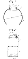
- FIG. 1 is a cross-sectional view of a device for confirming the position of a branch pipe opening according to the first embodiment (taken along a line A-A in Fig. 2)
- Fig. 2 is a lateral view of the device.
- the device for confirming the position of a branch pipe opening (hereinafter simply referred to as the "device") 1 comprises a holder member 2 having an arcuate shape conformal to the inner wall of a main pipe 10 (see Fig. 6); and a protrusion or a cylinder portion 3 extending in the radial direction of the holder member 2 and protruding from the inner and outer surfaces of the holder member 2 by a predetermined length.
- the protrusion 3 has an opening which is substantially the same in shape as that of a branch pipe opening (an end of a branch pipe 11 open to the main pipe 10) lla (see Fig. 6).
- the holder member 2 may be made of elastic plastic material, wood, or metal.
- the outer diameter D1 of the holder member 2 before the device 1 is introduced into the main pipe 10 for a lining operation, later described, is set larger than the inner diameter D of the main pipe 10 (D1>D), while the width B of the holder member 2 is set larger than the outer diameter dl of the cylinder portion 3 (B>d1).
- the circumferential length of the holder member 2 is set longer than one half of the circumference of the inner wall of the main pipe 10.
- the protrusion 3 is made separately from the holder member 2 in this embodiment, it should be understood that they may be integrated with each other.
- the outer diameter dl of the protrusion 3 is slightly smaller than the diameter d of a branch pipe 11 (see Fig. 6), later described, (d1 ⁇ d), by a margin for inserting the protrusion 3 into the branch pipe 11.
- the upper and lower end surfaces of the protrusion 3 may be curved as illustrated in Fig. 3. Also, in a further embodiment, the protrusion 3 may extend only toward the inner wall of the holder member 2, as illustrated in Fig. 4.
- the circumferential length of the holder member 2 of the device 1 may be set shorter than one half of the circumference of the inner wall of the main pipe 10, with the outer surface of the holder member 2 being impregnated or applied with a bonding agent.
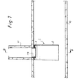
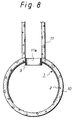
- FIGS. 6 through 13 are cross-sectional views illustrating in order various steps of the pipe lining method according to an embodiment of the present invention, where Fig. 8 is a cross-sectional view taken along a line B-B in Fig. 7, and Fig. 11 is a cross-sectional view taken along a line C-C in Fig. 10.
- a main pipe 10 of a sewage pipe line for example, includes a branch pipe 11 having a smaller diameter and confluent thereto as illustrated.
- the aforementioned device 1 is introduced into the main pipe 10 and positioned such that the protrusion 3 is inserted into a branch pipe opening 11a.
- the main pipe 10 is lined with a main pipe liner bag 12 (see Fig. 9), and a portion of the main pipe liner bag 12 is cut along a mark 12a (see Figs. 10 and 11) formed by the protrusion 3 of the device 1 conformal to the branch pipe opening lla and protruding under the main pipe liner bag 12.
- an in-pipe working robot 13 is introduced into the main pipe 10.
- the device 1 is set on a head 13a at a leading end of the in-pipe working robot 13 in a diameter compressed state (in a state in which the diameter of the holder member 2 is compressed to a size smaller than the inner diameter D of the main pipe 10) with the protrusion 3 facing upward.
- the in-pipe working robot 13 is hydraulically driven with the head 13a being movable in a direction indicated by arrows a and rotatable in a direction indicated by arrows b .
- the in-pipe working robot 13 is provided with pull rope 14, 15 linked thereto and with a TV camera 16 for monitoring on the top surface thereof.
- the in-pipe working robot 13 is moved by pulling the pull rope 14 or 15 while monitoring the inside of the main pipe 10 on the ground through the TV camera 16 installed on the in-pipe working robot 13. Then, the device 1 is positioned such that the protrusion 3 thereof matches the position of the branch pipe opening 11a. It should be noted that since the device 1 is set on the in-pipe working robot 13 in the diameter compressed state, the device 1 and the in-pipe working robot 13 can be freely moved without any obstacles.
- the device 1 After the device 1 is positioned as described above, the device 1 is released from the diameter compressed state. Since the holder member 2 of the device 1 is made of an elastic material as mentioned above, and the outer diameter D1 of the holder member 2 before the device 1 is introduced into the main pipe 10 is set larger the inner diameter D of the main pipe 10 (D1>D), the holding member 2 extends due to its elasticity when the device 1 is released from the diameter compressed state, as illustrated in Fig. 7 and 8, to closely contact the inner wall of the main pipe 10, whereby the device 1 is secured in position within the main pipe 10, and the protrusion 3 of the device 1 is inserted into the branch pipe opening 11a, with a portion of the protrusion 3 extending into the main pipe 10 as illustrated.
- the main pipe 10 is lined in the next step.
- a main pipe liner bag 12 is everted into the main pipe with a fluid pressure.
- the main pipe liner bag 12 comprises a tubular resin absorbent material 12c impregnated with an unhardened liquid hardenable resin.
- the tubular resin absorbent material 12c has its outer surface coated with a highly air-tight plastic film 12b.
- a material for the unwoven fabric constituting the tubular resin absorbent material 12c may be selected from polyester, polypropylene, nylon, acrylic fabric or the like.
- the unhardened liquid hardenable resin impregnated in the tubular resin absorbent material 12c may be a thermosetting resin such as unsaturated polyester resin, epoxy resin, vinyl ester resin, or the like.
- the plastic film 12b may be made in a single-layer or multi-layer seamless tube by an inflation method, and a material therefor may be selected from polyurethane, polyethylene, nylon, ethylene vinyl alcohol, admer, ionomer, vinyl chloride, and so on.
- the main pipe liner bag 12 when the main pipe liner bag 12 has been completely everted into the main pipe 10 over the entire length of the main pipe 10, the main pipe liner bag 12 is heated by an arbitrary heating means to harden the thermosetting resin impregnated therein, with the main pipe liner bag 12 urged against the inner wall of the main pipe 10 with a fluid pressure (hardening pressure) applied inside the main pipe liner bag 12.
- a fluid pressure hardening pressure
- a mark 12a conformal to the branch pipe opening 11a is protrusively formed on the main pipe liner bag 12 by the cylindrical portion 2 of the device 1 extending to the main pipe 10.
- the branch pipe opening 11a of the main pipe 10 is covered with the main pipe liner bag 12, so that a portion of the main pipe liner bag 12 covering the branch pipe opening 11a must be cut away to communicate the branch pipe 11 with the main pipe 10, as illustrated in Fig. 12.
- the in-pipe working robot 13 is introduced into the main pipe 10 for cutting the main pipe inner bag 12, as illustrated in Fig. 12.
- the in-pipe working robot 13 is provided with a hydraulic cylinder 17 mounted to the head 13a.
- the hydraulic cylinder 17 is provided with a hydraulic motor 18 supported by a rod 17a which is movable in the vertical direction as indicated by arrows c in the figure.
- a cutter 19 having an outer diameter smaller than the diameter of the branch pipe opening 11a is mounted on an output shaft of the hydraulic motor 18, the cutter 19 being formed with cutting blades on the upper and lower surfaces as well as on the outer peripheral surface.
- a reamer 19a is also mounted on a central portion of the upper surface of the cutter 19.
- the in-pipe working robot 13 is moved within the main pipe 10 by pulling the pull rope 14 or 15 and the cutter 19 is appropriately positioned, while monitoring the inside of the main pipe 10 through the TV camera 16 installed on the in-pipe working robot 13.
- the hydraulic motor 18 is driven to rotate the cutter 19 while the hydraulic cylinder 17 is driven to move the hydraulic motor 18 and the cutter 19 upward, causing the cutter 19 to cut the portion of the main pipe liner bag 12 covering the branch pipe opening 11a.
- the mark 12a is protrusively formed on the main pipe liner bag 12, conformal to the branch pipe opening lla by the protrusion 3 of the device 1, as described above, the mark 12a can be easily found, so that the main pipe liner bag 12 can be exactly cut along the mark 12a.
- the liquid thermosetting resin impregnated in the main pipe liner bag 12 will never ooze into the branch pipe 11 and harden.
- the main pipe liner bag 12 can be exactly cut along the mark 12a conformal to the branch pipe opening 11a which is protrusively formed on the main pipe liner bag 12.
- the periphery of the branch pipe opening 11a Since the periphery of the branch pipe opening 11a is covered and protected by the protrusion 3 of the device 1, the periphery of the branch pipe opening 11a will not be damaged by the cutter 19, thus preventing underground water or the like from intruding through a damaged portion into the main pipe 10.
- a holding force provided only by extending the holder member 2 within the main pipe 10 may not be sufficient.
- the outer surface of the holder member 2 is impregnated or applied with a bonding agent, a bonding force of the bonding agent helps hold the device 1 (or the holder member 2) on the inner surface of the main pipe 10, thereby preventing the device 1 from dropping.
- Fig. 14 is a cross-sectional view of a device for confirming the position of a branch pipe opening according to the second embodiment
- Fig. 15 is a perspective view of the device for confirming the position of a branch pipe opening
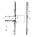
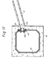
- Figs. 16 and 17 are lateral cross-sectional views illustrating in order steps of a pipe lining method using the device for confirming the position of a branch pipe opening according to the second embodiment.
- the second embodiment is particularly applicable to a main pipe which is large enough to allow a human to enter.
- a device 21 for confirming the position of a branch pipe opening (hereinafter simply referred to as the "device") according to the second embodiment comprises a flange 23 which abuts to the inner wall of a main pipe of a box culvert type (see Fig. 16) around the periphery of a branch pipe opening 31a, when the device 21 is set in position; and a protrusion 23 formed in a portion of the flange 22 to have an opening substantially conformal to the branch pipe opening 31a and to extend through the flange 22.
- the protrusion 23 protrudes from the inner and outer surface of the flange 22 by a predetermined length.
- the flange 22 is formed with four bolt bores 22 through four corner portions thereof for inserting anchor bolts 25 therethrough.
- the device 21 may be made of a plastic material or metal, and a portion 22A of the flange 22 is bent along the shape of the inner wall of the main pipe 30, as can be seen in Fig. 16.
- an operator may enter the main pipe 30 and manually mount the device 21 on the inner wall of the main pipe 30 around the periphery of the branch pipe opening 31a as illustrated in Fig. 16. More specifically, the protrusion 23 of the device 21 is positioned at the branch pipe opening 31a, the flange 22 of the device 21 is brought into contact with the inner wall of the main pipe 30 around the periphery of the branch pipe opening 31a, and the device 21 is secured on the inner wall of the main pipe 30 by the anchor bolts 25 inserted through the bolt bores 22a formed through the flange 22.
- a branch pipe 31 of a smaller diameter is illustrated as being confluent to the main pipe 30.
- the main pipe 30 is lined using a main pipe liner bag 32 in a manner similar to the first embodiment, wherein a mark 31a substantially conformal to the branch pipe opening 31a is protrusively formed on the main pipe liner bag 32 due to the protrusion 23 of the device 21 extending toward the main pipe 30.
- the mark 32a formed on the main pipe liner bag 32 can be easily found when cutting the portion of the main pipe liner bag 32 covering the branch pipe opening 31a, so that the main pipe liner bag 32 can be exactly cut along the mark 32a, as is the case of the first embodiment.
- the second embodiment allows an operator to enter the main pipe 30 to manually cut the main pipe liner bag.
- the pipe lining method using the device for confirming the position of a branch pipe opening of the first embodiment when the device for confirming the position of a branch pipe opening is set within a main pipe, the protrusion of the device is inserted into a branch pipe opening for positioning, and the main pipe is lined using a main pipe liner bag, the protrusion of the device for confirming the position of a branch pipe opening causes a mark substantially conformal to the branch pipe opening to be protrusively formed on the main pipe liner bag, so that the main pipe liner bag can be exactly cut along the mark.
- the main pipe liner bag can be exactly cut along a mark substantially conformal to the branch pipe opening, protrusively formed on the main pipe liner bag by the device for confirming the position of a branch pipe opening of the present invention.
- a mark substantially conformal to the branch pipe opening is protrusively formed on the main pipe liner bag by the protrusion of the device for confirming the position of a branch pipe opening, so that the main pipe liner bag can be exactly cut along the mark.
Landscapes
- Engineering & Computer Science (AREA)
- General Engineering & Computer Science (AREA)
- Mechanical Engineering (AREA)
- Manufacturing & Machinery (AREA)
- Lining Or Joining Of Plastics Or The Like (AREA)
- Pipe Accessories (AREA)
Applications Claiming Priority (3)
| Application Number | Priority Date | Filing Date | Title |
|---|---|---|---|
| JP19364497 | 1997-07-18 | ||
| JP19364497 | 1997-07-18 | ||
| JP193644/97 | 1997-07-18 |
Publications (3)
| Publication Number | Publication Date |
|---|---|
| EP0891857A2 true EP0891857A2 (fr) | 1999-01-20 |
| EP0891857A3 EP0891857A3 (fr) | 2000-02-02 |
| EP0891857B1 EP0891857B1 (fr) | 2002-10-23 |
Family
ID=16311380
Family Applications (1)
| Application Number | Title | Priority Date | Filing Date |
|---|---|---|---|
| EP98305735A Expired - Lifetime EP0891857B1 (fr) | 1997-07-18 | 1998-07-17 | Dispositif pour repérer la position de l'entrée d'une conduite de dérivation et méthode de revêtement de conduites utilisant ce dispositif |
Country Status (6)
| Country | Link |
|---|---|
| EP (1) | EP0891857B1 (fr) |
| KR (1) | KR19990013994A (fr) |
| CA (1) | CA2243572A1 (fr) |
| DE (1) | DE69808850T2 (fr) |
| DK (1) | DK0891857T3 (fr) |
| TW (1) | TW386936B (fr) |
Cited By (6)
| Publication number | Priority date | Publication date | Assignee | Title |
|---|---|---|---|---|
| EP0931639A3 (fr) * | 1998-01-27 | 2000-01-26 | Shonan Gosei - Jushi Seisakusho K.K. | Procédé de revêtement de tuyaux |
| EP0978681A1 (fr) * | 1998-08-06 | 2000-02-09 | Shonan Gosei - Jushi Seisakusho K.K. | Revêtement pour une conduite de dérivation et procédé de revêtement d'une conduite de dérivation |
| WO2000055539A1 (fr) * | 1999-03-18 | 2000-09-21 | Thames Water Utilities Limited | Conduites de distribution |
| WO2006107461A3 (fr) * | 2005-04-04 | 2007-04-19 | Lmk Entpr Inc | Procede et appareil d'identification d'une conduite laterale |
| WO2014067862A1 (fr) * | 2012-10-30 | 2014-05-08 | Sekisui Norditube Technologies Se | Procédé et appareil pour rendre étanche une jonction entre un tube principal à revêtement et un tube latéral raccordé à celui-ci |
| EP2738438A1 (fr) * | 2012-11-28 | 2014-06-04 | Sekisui Norditube Technologies SE | Procédé et appareil permettant d'étanchéifier un raccord entre un tuyau principal chemisé et un tuyau latéral relié à celui-ci |
Family Cites Families (10)
| Publication number | Priority date | Publication date | Assignee | Title |
|---|---|---|---|---|
| GB1026000A (en) * | 1965-03-12 | 1966-04-14 | Standard Telephones Cables Ltd | Improvements in or relating to pipework connectors |
| FR2456280A1 (fr) * | 1979-05-11 | 1980-12-05 | Syndicat Nal Prof Entre Trav D | Raccord de branchement d'un drain sur un collecteur |
| WO1990007418A1 (fr) * | 1989-01-06 | 1990-07-12 | Ashimori Kogyo Kabushiki Kaisha | Dispositif et instrument utilises pour revetir une conduite a embranchements |
| US4893841A (en) * | 1989-04-20 | 1990-01-16 | Bowen William D | Reamer guide for primary sewer line taps |
| KR970001692B1 (ko) * | 1990-02-15 | 1997-02-13 | 신기찌 오오까 | 관로의 지수방법과 관로의 연결부 구조체 및 지수재 |
| DE4024926A1 (de) * | 1990-08-06 | 1992-02-13 | Otto Schlemmer Gmbh | Verfahren und vorrichtung zum sanieren von rohren |
| GB9225528D0 (en) * | 1992-12-07 | 1993-01-27 | Insituform Group Ltd | Improvements relating to the lining of pipelines and passageways |
| JPH08426B2 (ja) * | 1993-04-13 | 1996-01-10 | 株式会社湘南合成樹脂製作所 | 管ライニング材とその製造方法及び管路補修工法 |
| DE4328411A1 (de) * | 1993-08-24 | 1995-03-02 | Stehmeyer & Bischoff Gmbh Co | Verfahren und Vorrichtung zum Anschließen und Abdichten eines Seitenzulaufs an einen mit einem Inliner aus Kunststoff zu sanierenden Hauptkanal |
| KR101026000B1 (ko) * | 2009-01-22 | 2011-03-30 | 엘에스엠트론 주식회사 | 저항층 코팅 도전체 및 그 제조방법과 인쇄회로기판 |
-
1998
- 1998-07-14 TW TW087111451A patent/TW386936B/zh active
- 1998-07-16 CA CA002243572A patent/CA2243572A1/fr not_active Abandoned
- 1998-07-17 DE DE69808850T patent/DE69808850T2/de not_active Expired - Fee Related
- 1998-07-17 EP EP98305735A patent/EP0891857B1/fr not_active Expired - Lifetime
- 1998-07-17 DK DK98305735T patent/DK0891857T3/da active
- 1998-07-18 KR KR1019980029035A patent/KR19990013994A/ko not_active Ceased
Cited By (11)
| Publication number | Priority date | Publication date | Assignee | Title |
|---|---|---|---|---|
| EP0931639A3 (fr) * | 1998-01-27 | 2000-01-26 | Shonan Gosei - Jushi Seisakusho K.K. | Procédé de revêtement de tuyaux |
| EP0978681A1 (fr) * | 1998-08-06 | 2000-02-09 | Shonan Gosei - Jushi Seisakusho K.K. | Revêtement pour une conduite de dérivation et procédé de revêtement d'une conduite de dérivation |
| AU770104B2 (en) * | 1998-08-06 | 2004-02-12 | Get Inc. | Branch pipe liner bag and pipe lining method |
| WO2000055539A1 (fr) * | 1999-03-18 | 2000-09-21 | Thames Water Utilities Limited | Conduites de distribution |
| WO2006107461A3 (fr) * | 2005-04-04 | 2007-04-19 | Lmk Entpr Inc | Procede et appareil d'identification d'une conduite laterale |
| US7306011B2 (en) | 2005-04-04 | 2007-12-11 | Lmk Enterprises, Inc. | Apparatus and method for lateral pipe identification |
| US7426941B2 (en) | 2005-04-04 | 2008-09-23 | Lmk Enterprises, Inc. | Apparatus and method for lateral pipe identification |
| US7588054B2 (en) | 2005-04-04 | 2009-09-15 | Lmk Enterprises, Inc. | Apparatus and method for lateral pipe identification |
| AU2006233017B2 (en) * | 2005-04-04 | 2010-02-25 | Lmk Technologies, Llc | Apparatus and method for lateral pipe identification |
| WO2014067862A1 (fr) * | 2012-10-30 | 2014-05-08 | Sekisui Norditube Technologies Se | Procédé et appareil pour rendre étanche une jonction entre un tube principal à revêtement et un tube latéral raccordé à celui-ci |
| EP2738438A1 (fr) * | 2012-11-28 | 2014-06-04 | Sekisui Norditube Technologies SE | Procédé et appareil permettant d'étanchéifier un raccord entre un tuyau principal chemisé et un tuyau latéral relié à celui-ci |
Also Published As
| Publication number | Publication date |
|---|---|
| EP0891857B1 (fr) | 2002-10-23 |
| TW386936B (en) | 2000-04-11 |
| CA2243572A1 (fr) | 1999-01-18 |
| DE69808850D1 (de) | 2002-11-28 |
| DE69808850T2 (de) | 2003-08-07 |
| EP0891857A3 (fr) | 2000-02-02 |
| DK0891857T3 (da) | 2002-11-18 |
| KR19990013994A (ko) | 1999-02-25 |
Similar Documents
| Publication | Publication Date | Title |
|---|---|---|
| US6056017A (en) | Pipe lining method | |
| US6085794A (en) | Pipe lining method | |
| EP0978681B1 (fr) | Revêtement pour une conduite de dérivation et procédé de revêtement d'une conduite de dérivation | |
| US4995761A (en) | Method and apparatus for repairing ruptures in underground conduits | |
| EP0620102B1 (fr) | Méthode de revêtement et revêtement pour tuyaux de dérivation | |
| US5049003A (en) | Method and apparatus for repairing ruptures in underground conduits | |
| EP0938964B1 (fr) | Revêtement pour une conduite de dérivation et procédé de revêtement d'une conduite de dérivation | |
| US6199591B1 (en) | Method of using detachable lines for positioning pipeline repair liner | |
| US5916406A (en) | Branch pipe liner bag and pipe lining method | |
| US6103052A (en) | Pipe lining method | |
| US6006787A (en) | Branch pipe liner bag and branch pipe lining method | |
| JPH10278115A (ja) | 枝管ライニング材及び管ライニング工法 | |
| EP0908661A2 (fr) | Chemisage d'un branchement et procédé de chemisage | |
| US10683959B2 (en) | Method and apparatus for repairing a length of pipe or a main/lateral pipe junction | |
| EP0891857B1 (fr) | Dispositif pour repérer la position de l'entrée d'une conduite de dérivation et méthode de revêtement de conduites utilisant ce dispositif | |
| AU7841098A (en) | Device for confirming the position of branch pipe opening and pipe lining method using the device | |
| EP0911568B1 (fr) | Dispositif de revêtement d'un tuyau de dérivation et procédé pour le revêtement d'un tuyau | |
| JP2702099B2 (ja) | 枝管用鍔付スタートライナー及び管ライニング工法 | |
| JP3221837B2 (ja) | 管路用ライニング材 | |
| JP3123932B2 (ja) | 鍔付筒状ライニング材 | |
| JPH1177829A (ja) | 枝管開口部目印用治具及び管ライニング工法 | |
| JPH10202745A (ja) | 枝管ライニング材及び管ライニング工法 |
Legal Events
| Date | Code | Title | Description |
|---|---|---|---|
| PUAI | Public reference made under article 153(3) epc to a published international application that has entered the european phase |
Free format text: ORIGINAL CODE: 0009012 |
|
| AK | Designated contracting states |
Kind code of ref document: A2 Designated state(s): DE DK FR GB |
|
| AX | Request for extension of the european patent |
Free format text: AL;LT;LV;MK;RO;SI |
|
| PUAL | Search report despatched |
Free format text: ORIGINAL CODE: 0009013 |
|
| AK | Designated contracting states |
Kind code of ref document: A3 Designated state(s): AT BE CH CY DE DK ES FI FR GB GR IE IT LI LU MC NL PT SE |
|
| AX | Request for extension of the european patent |
Free format text: AL;LT;LV;MK;RO;SI |
|
| 17P | Request for examination filed |
Effective date: 20000721 |
|
| AKX | Designation fees paid |
Free format text: DE DK FR GB |
|
| 17Q | First examination report despatched |
Effective date: 20010328 |
|
| GRAG | Despatch of communication of intention to grant |
Free format text: ORIGINAL CODE: EPIDOS AGRA |
|
| GRAG | Despatch of communication of intention to grant |
Free format text: ORIGINAL CODE: EPIDOS AGRA |
|
| GRAH | Despatch of communication of intention to grant a patent |
Free format text: ORIGINAL CODE: EPIDOS IGRA |
|
| GRAH | Despatch of communication of intention to grant a patent |
Free format text: ORIGINAL CODE: EPIDOS IGRA |
|
| GRAA | (expected) grant |
Free format text: ORIGINAL CODE: 0009210 |
|
| AK | Designated contracting states |
Kind code of ref document: B1 Designated state(s): DE DK FR GB |
|
| REG | Reference to a national code |
Ref country code: GB Ref legal event code: FG4D |
|
| REG | Reference to a national code |
Ref country code: DK Ref legal event code: T3 |
|
| REF | Corresponds to: |
Ref document number: 69808850 Country of ref document: DE Date of ref document: 20021128 |
|
| ET | Fr: translation filed | ||
| PLBE | No opposition filed within time limit |
Free format text: ORIGINAL CODE: 0009261 |
|
| STAA | Information on the status of an ep patent application or granted ep patent |
Free format text: STATUS: NO OPPOSITION FILED WITHIN TIME LIMIT |
|
| 26N | No opposition filed |
Effective date: 20030724 |
|
| PGFP | Annual fee paid to national office [announced via postgrant information from national office to epo] |
Ref country code: DK Payment date: 20031229 Year of fee payment: 6 |
|
| PGFP | Annual fee paid to national office [announced via postgrant information from national office to epo] |
Ref country code: FR Payment date: 20031231 Year of fee payment: 6 |
|
| PGFP | Annual fee paid to national office [announced via postgrant information from national office to epo] |
Ref country code: GB Payment date: 20040714 Year of fee payment: 7 |
|
| PGFP | Annual fee paid to national office [announced via postgrant information from national office to epo] |
Ref country code: DE Payment date: 20040729 Year of fee payment: 7 |
|
| PG25 | Lapsed in a contracting state [announced via postgrant information from national office to epo] |
Ref country code: DK Free format text: LAPSE BECAUSE OF NON-PAYMENT OF DUE FEES Effective date: 20040802 |
|
| REG | Reference to a national code |
Ref country code: DK Ref legal event code: EBP |
|
| PG25 | Lapsed in a contracting state [announced via postgrant information from national office to epo] |
Ref country code: FR Free format text: LAPSE BECAUSE OF NON-PAYMENT OF DUE FEES Effective date: 20050331 |
|
| REG | Reference to a national code |
Ref country code: FR Ref legal event code: ST |
|
| PG25 | Lapsed in a contracting state [announced via postgrant information from national office to epo] |
Ref country code: GB Free format text: LAPSE BECAUSE OF NON-PAYMENT OF DUE FEES Effective date: 20050717 |
|
| PG25 | Lapsed in a contracting state [announced via postgrant information from national office to epo] |
Ref country code: DE Free format text: LAPSE BECAUSE OF NON-PAYMENT OF DUE FEES Effective date: 20060201 |
|
| GBPC | Gb: european patent ceased through non-payment of renewal fee |
Effective date: 20050717 |