EP0891893A2 - Système d'interrupteur - Google Patents
Système d'interrupteur Download PDFInfo
- Publication number
- EP0891893A2 EP0891893A2 EP98106227A EP98106227A EP0891893A2 EP 0891893 A2 EP0891893 A2 EP 0891893A2 EP 98106227 A EP98106227 A EP 98106227A EP 98106227 A EP98106227 A EP 98106227A EP 0891893 A2 EP0891893 A2 EP 0891893A2
- Authority
- EP
- European Patent Office
- Prior art keywords
- switching
- switching element
- switch
- arrangement according
- electrical contacts
- Prior art date
- Legal status (The legal status is an assumption and is not a legal conclusion. Google has not performed a legal analysis and makes no representation as to the accuracy of the status listed.)
- Withdrawn
Links
Images
Classifications
-
- H—ELECTRICITY
- H02—GENERATION; CONVERSION OR DISTRIBUTION OF ELECTRIC POWER
- H02B—BOARDS, SUBSTATIONS OR SWITCHING ARRANGEMENTS FOR THE SUPPLY OR DISTRIBUTION OF ELECTRIC POWER
- H02B15/00—Supervisory desks or panels for centralised control or display
- H02B15/02—Supervisory desks or panels for centralised control or display with mimic diagrams
- H02B15/04—Supervisory desks or panels for centralised control or display with mimic diagrams consisting of building blocks
-
- H—ELECTRICITY
- H01—ELECTRIC ELEMENTS
- H01H—ELECTRIC SWITCHES; RELAYS; SELECTORS; EMERGENCY PROTECTIVE DEVICES
- H01H25/00—Switches with compound movement of handle or other operating part
- H01H25/04—Operating part movable angularly in more than one plane, e.g. joystick
- H01H25/041—Operating part movable angularly in more than one plane, e.g. joystick having a generally flat operating member depressible at different locations to operate different controls
-
- E—FIXED CONSTRUCTIONS
- E05—LOCKS; KEYS; WINDOW OR DOOR FITTINGS; SAFES
- E05F—DEVICES FOR MOVING WINGS INTO OPEN OR CLOSED POSITION; CHECKS FOR WINGS; WING FITTINGS NOT OTHERWISE PROVIDED FOR, CONCERNED WITH THE FUNCTIONING OF THE WING
- E05F15/00—Power-operated mechanisms for wings
-
- E—FIXED CONSTRUCTIONS
- E05—LOCKS; KEYS; WINDOW OR DOOR FITTINGS; SAFES
- E05Y—INDEXING SCHEME ASSOCIATED WITH SUBCLASSES E05D AND E05F, RELATING TO CONSTRUCTION ELEMENTS, ELECTRIC CONTROL, POWER SUPPLY, POWER SIGNAL OR TRANSMISSION, USER INTERFACES, MOUNTING OR COUPLING, DETAILS, ACCESSORIES, AUXILIARY OPERATIONS NOT OTHERWISE PROVIDED FOR, APPLICATION THEREOF
- E05Y2400/00—Electronic control; Electrical power; Power supply; Power or signal transmission; User interfaces
- E05Y2400/80—User interfaces
- E05Y2400/85—User input means
- E05Y2400/852—Sensors
- E05Y2400/854—Switches
-
- E—FIXED CONSTRUCTIONS
- E05—LOCKS; KEYS; WINDOW OR DOOR FITTINGS; SAFES
- E05Y—INDEXING SCHEME ASSOCIATED WITH SUBCLASSES E05D AND E05F, RELATING TO CONSTRUCTION ELEMENTS, ELECTRIC CONTROL, POWER SUPPLY, POWER SIGNAL OR TRANSMISSION, USER INTERFACES, MOUNTING OR COUPLING, DETAILS, ACCESSORIES, AUXILIARY OPERATIONS NOT OTHERWISE PROVIDED FOR, APPLICATION THEREOF
- E05Y2400/00—Electronic control; Electrical power; Power supply; Power or signal transmission; User interfaces
- E05Y2400/80—User interfaces
- E05Y2400/85—User input means
- E05Y2400/856—Actuation thereof
- E05Y2400/858—Actuation thereof by body parts, e.g. by feet
- E05Y2400/86—Actuation thereof by body parts, e.g. by feet by hand
-
- E—FIXED CONSTRUCTIONS
- E05—LOCKS; KEYS; WINDOW OR DOOR FITTINGS; SAFES
- E05Y—INDEXING SCHEME ASSOCIATED WITH SUBCLASSES E05D AND E05F, RELATING TO CONSTRUCTION ELEMENTS, ELECTRIC CONTROL, POWER SUPPLY, POWER SIGNAL OR TRANSMISSION, USER INTERFACES, MOUNTING OR COUPLING, DETAILS, ACCESSORIES, AUXILIARY OPERATIONS NOT OTHERWISE PROVIDED FOR, APPLICATION THEREOF
- E05Y2900/00—Application of doors, windows, wings or fittings thereof
- E05Y2900/50—Application of doors, windows, wings or fittings thereof for vehicles
- E05Y2900/53—Type of wing
- E05Y2900/55—Windows
-
- H—ELECTRICITY
- H01—ELECTRIC ELEMENTS
- H01H—ELECTRIC SWITCHES; RELAYS; SELECTORS; EMERGENCY PROTECTIVE DEVICES
- H01H2300/00—Orthogonal indexing scheme relating to electric switches, relays, selectors or emergency protective devices covered by H01H
- H01H2300/01—Application power window
Definitions
- the invention relates to a switch arrangement for the central Operating a plurality of components or assemblies one Motor vehicle.
- switches For operating components or assemblies of a motor vehicle switches are generally used, both in immediate area of the components to be operated or Assemblies as well as in a central position for operation the components or assemblies are arranged.
- switches are one or more switch functions for each switch assigned to a specific component or a specific assembly. That means that to actuate the components or assemblies individual separate switches are required, the Switches must be operated sequentially. In close proximity the switch to each other can be operated in parallel Components or assemblies only achieved in a complicated way be put by the fingers of an operator's hand several switches can be extended. However, this can result in a insufficient actuation force on the actuators intended switches or unintended ones Actuation of switches or a certain operating function the same lead, causing incorrect switching can.
- this object is achieved by Switch arrangement with a visible top having switch panel with a plurality of one another adjacent switching sections, which with electrical Contacts are provided, and a switching element, which is longitudinal the visible top to each of the switching sections is so displaceable that this by contacting the electrical contacts are switchable.
- this object is further achieved by Switch arrangement with a visible top having switch panel with a plurality of one another adjacent pressure or touch switches, and one switching element switchable between two polarity reversal positions, which with each of the push or touch switches in electrical contact can be brought.
- Such a switch arrangement enables a central one Operate a plurality of components or assemblies that individually or in combination with each other Switching sections or one of the pressure or touch switches can be assigned, the switching element one or several operating functions of the respective components or Assemblies can be assigned. Either the Components or assemblies using the respective Switching section or pressure or touch switch selected and the operating function of the respective components or Assemblies are switched on by means of the switching element, or the operating function of the respective components or assemblies selected by means of the switching element and the components or Assemblies by means of the respective switching section or pressure or Touch switch can be switched on. Consequently is from the switching element and the respective switching section or pressure or touch switch an electrical contact triggered, which causes the respective operating function of the Components or assemblies of the motor vehicle is executed.
- the switch arrangement according to the invention does not leave only one flexible switching of possible combinations for the Activate the components or assemblies, but allows also recognizing the position of the respective components or Assemblies from the location of the assigned Switching section or pressure or touch switch within of the control panel, which ensures good clarity and a quick operation of the components or assemblies guaranteed is.
- the visible top of the panel can be found in the Motor vehicle can be arranged so that it from a Operator is clearly recognizable, with an additional optical identification of the switching sections or pressure or Touch switch and the switching element with the help of Illuminants that are permanent or only during certain Operations are effective, is appropriate.
- the arrangement of the Switching sections or pressure or touch switches and the Switching element to each other enables a clear tactility by the operator, so that incorrect switching can be avoided and an exact assignment of the switching element to the switching contact of the respective switching section or pressure or Touch switch of the control panel is reached.
- the top of the panel just be formed, and the switching element a flat bottom have, which rests on the top of the panel.
- the Shift of the switching element to the switching sections of the Switch panel can along predetermined lines or in done in any way.
- the switching sections by bridging their electrical Contacts can be switched by means of the switching elements.
- the switching element with appropriate means is provided with the electrical contacts of the respective Switching sections of the control panel can be brought into engagement.
- the switching element with electrical contacts be used to switch the switching sections with their electrical contacts can be contacted.
- the respective electrical contacts of the switching elements and the Switching section in direct contact with each other to the corresponding actuation process on the components and Trigger assemblies. It is useful here Switching element by means of an additional guide element to lead the respective switching section to then to be able to make the electrical contact.
- the switching sections of the Control panel with locking elements for preselecting the components or Assemblies are provided.
- the switching element in the panel can switch the switching element in the panel be integrated.
- the use of touch switches is particularly advantageous since it is not a large one Require actuation force.
- the integrated in the panel Arrangement of the switching element ensures simple Usability and, as a compact block, requires little Installation space.
- the Switching element from the pressure or touch switches of the Be surrounded and protrude upwards.
- every pressure or touch switch is in the immediate vicinity Proximity to the switching element, which makes a clear Usability from the position of the switching element to the respective pressure or touch switches guaranteed is.
- the above arrangement of the switching element enables the same to be clearly recognized by the Operator and prevents accidental touching of Pressure or touch switches of the control panel when actuated of the switching element.
- the Switching element can be arranged separately from the control panel.
- the area of the switching element and the respective pressure or Touch switch of the control panel can accordingly be designed more generously so that incorrect operation of both the Switching element as well as the pressure or touch switch be avoided.
- the printing or Touch switch of the control panel as pre-selection elements be trained. This has the advantage that after preselection the operating function of the respective components or assemblies the same by switching the switching element between the two Reverse polarity can be changed.
- the switching element is also advantageous to use the switching element as Train double switches or double touch switches. This allows two different operating functions, such as the Raising and lowering an electric window lifter Motor vehicle, are switched. There is no reset here of the switching element after completion of the actuation process required, as is the case, for example, with a latching switch Case is, which makes it easy to use Switching element is guaranteed.
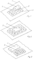
- FIG. 1 shows a switch arrangement on a center console 1 a four-door motor vehicle can be seen leading to the central Operation of electric windows is suitable, one Switching element 2 on a flat upper side of a switching field 3 is slidably arranged.
- the control panel 3 has nine adjacent switching sections on and is from aligned vertically to the flat top of the control panel 3 electrical contacts 4 limited.
- the switching element 2 is on its side surfaces provided with electrical contacts 5, the can be contacted with the electrical contacts 4.
- the Switching sections of the control panel 3 are not shown Provide locking elements with which the switching element 2 in Intervention can be brought.
- the respective electric windows individually or in Pre-selectable combination.
- the switching sections of the control panel 3 are corresponding the position of the respective window regulator in the motor vehicle Switching section I the front left window regulator, the Switching section III the right front window lifter, the Switching section VII the rear left window regulator and the Switching section IX assigned to the rear right window regulator.
- the switching section II are both front windows, the Switching section IV both left window regulator, the Switching section V all window regulators, the switching section VI both right window regulators and the switching section VII both assigned rear window regulator.
- the switching element 2 is designed as a double button can be switched between two polarity reversal positions Lowering assigned to the respective power window are.
- the switching element 2 is to each of the switching sections of the Panel 3 slidable and with the locking element of respective switching section can be brought into engagement in such a way that the electrical contacts 5 of the switching element 2 with the to respective switching section adjacent electrical contacts 4 of the control panel 3 are in contact.
- the switching element is located 2 in engagement with the switching section I, the electrical Contacts 5 of the switching element 2 with the electrical contacts 4, which adjoin the switching section I and assigned to it are in contact, causing the front left window regulator is selected.
- the switching element 2 is depressed on the corresponding side.
- the function assigned to the switching section V can also be preselected with one another in this way be that no contacting of the electrical contacts 4 and 5 with each other he follows.
- a switch arrangement can be seen from FIG. 2, the switching element 2 from the control panel 3 is surrounded, which has eight pressure switches, each one Window regulators or a combination of window regulators are assigned.
- the Switching element 2 is designed as a double button and projects upwards.
- the respective window regulator or the respective combination of window regulators is preselectable by pressing the corresponding pressure switch of the control panel 3 and can be raised by depressing the switching element 2 on the corresponding side or lowerable.
- the switching element 2 is arranged separately from the control panel 3, which has nine touch switches, each with a window regulator or a combination of window regulators assigned.
- the switching element 2 is a double touch switch educated.
- the respective window regulator or the respective combination of window regulators is preselectable by touching the corresponding touch switch of the control panel 3 and can be raised by touching the switching element 2 on the corresponding side or lowerable.
- the switch arrangements can be in the front area of the center console 1 between the driver and the front passenger or in the rear area of the center console 1 between be arranged on the rear seats for the passengers, the window regulators or the combinations of window regulators operated centrally by these people can be. With all versions, all or some switching sections can be arranged close to each other with a small distance.
Landscapes
- Engineering & Computer Science (AREA)
- Power Engineering (AREA)
- Push-Button Switches (AREA)
- Switch Cases, Indication, And Locking (AREA)
- Keying Circuit Devices (AREA)
Applications Claiming Priority (2)
| Application Number | Priority Date | Filing Date | Title |
|---|---|---|---|
| DE1997114955 DE19714955A1 (de) | 1997-04-10 | 1997-04-10 | Schalteranordnung |
| DE19714955 | 1997-04-10 |
Publications (2)
| Publication Number | Publication Date |
|---|---|
| EP0891893A2 true EP0891893A2 (fr) | 1999-01-20 |
| EP0891893A3 EP0891893A3 (fr) | 2001-01-24 |
Family
ID=7826104
Family Applications (1)
| Application Number | Title | Priority Date | Filing Date |
|---|---|---|---|
| EP98106227A Withdrawn EP0891893A3 (fr) | 1997-04-10 | 1998-04-06 | Système d'interrupteur |
Country Status (2)
| Country | Link |
|---|---|
| EP (1) | EP0891893A3 (fr) |
| DE (1) | DE19714955A1 (fr) |
Cited By (2)
| Publication number | Priority date | Publication date | Assignee | Title |
|---|---|---|---|---|
| EP1431996A3 (fr) * | 2002-12-20 | 2006-08-09 | Siemens Aktiengesellschaft | Dispositif d'entrée pour un appareil électrique |
| US8561008B2 (en) | 2005-03-10 | 2013-10-15 | Siemens Aktiengesellschaft | Presentation of hierarchical software structures |
Families Citing this family (1)
| Publication number | Priority date | Publication date | Assignee | Title |
|---|---|---|---|---|
| DE19910240A1 (de) * | 1999-03-08 | 2000-09-21 | Mannesmann Vdo Ag | Bedienvorrichtung |
Family Cites Families (6)
| Publication number | Priority date | Publication date | Assignee | Title |
|---|---|---|---|---|
| JPS60110941U (ja) * | 1983-12-28 | 1985-07-27 | 株式会社東海理化電機製作所 | スイツチ装置 |
| DE3703546A1 (de) * | 1987-02-06 | 1988-08-18 | Telefunken Electronic Gmbh | Schalter mit einer geschlossenen schaltmatte |
| JP2615607B2 (ja) * | 1987-04-07 | 1997-06-04 | ソニー株式会社 | 入力操作装置 |
| US5111006A (en) * | 1989-05-16 | 1992-05-05 | Kabushiki Kaisha Toka-Rika-Denki-Seisakusho | Switch device for power driven seat |
| US5111011A (en) * | 1990-07-26 | 1992-05-05 | Indak Manufacturing Corp. | Mirror control slide switch for automotive vehicles |
| DE4338171C1 (de) * | 1993-11-09 | 1995-04-20 | Daimler Benz Ag | Tastatur- und Anzeigesystem |
-
1997
- 1997-04-10 DE DE1997114955 patent/DE19714955A1/de not_active Withdrawn
-
1998
- 1998-04-06 EP EP98106227A patent/EP0891893A3/fr not_active Withdrawn
Cited By (2)
| Publication number | Priority date | Publication date | Assignee | Title |
|---|---|---|---|---|
| EP1431996A3 (fr) * | 2002-12-20 | 2006-08-09 | Siemens Aktiengesellschaft | Dispositif d'entrée pour un appareil électrique |
| US8561008B2 (en) | 2005-03-10 | 2013-10-15 | Siemens Aktiengesellschaft | Presentation of hierarchical software structures |
Also Published As
| Publication number | Publication date |
|---|---|
| EP0891893A3 (fr) | 2001-01-24 |
| DE19714955A1 (de) | 1998-10-15 |
Similar Documents
| Publication | Publication Date | Title |
|---|---|---|
| DE602004010753T2 (de) | Tastatur mit versenkbaren Tasten und Taste einer solchen Tastatur besonders geeignet für das Armaturenbrett eines Fahrzeugs | |
| DE2922276C2 (de) | Schalter | |
| EP0234193A2 (fr) | Agencement d'interrupteur | |
| DE102007051466A1 (de) | Schaltvorrichtung | |
| DE102017113661B4 (de) | Kraftfahrzeugbedienvorrichtung | |
| DE8119605U1 (de) | "Drucktastenschalter" | |
| DE69806452T2 (de) | Gerät zur Steuerung von elektrischen Fensterhebern | |
| DE4215097C2 (de) | Schalteranordnung | |
| DE4012399A1 (de) | Schaltervorrichtung | |
| DE2020838C3 (de) | Drucktastenschaltersperre mit Verdrängungskörpern | |
| DE3148855C2 (de) | Druck- oder Schiebetastenschalter | |
| DE4244583C1 (de) | Handbetätigter Steuerschalter | |
| DE19752774C5 (de) | Schalterkombination zur Betätigung elektrisch angetriebener Fenster in einem Fahrzeug | |
| DE3249955C2 (de) | Elektrischer Mehrpositions-Schalter | |
| EP0891893A2 (fr) | Système d'interrupteur | |
| DE19757231B4 (de) | Multifunktions-Schalteinrichtung für Kraftfahrzeuge | |
| DE3835073A1 (de) | Elektrischer schalter fuer eine kraftfahrzeug-fensterhebevorrichtung | |
| EP0817226A2 (fr) | Interrupteur à bascule | |
| EP3934930B1 (fr) | Circuit | |
| DE102006028462B4 (de) | Schalter zur Verstellung eines Fahrzeugsitzes | |
| DE102007042129B4 (de) | Mehrfachbedienelement | |
| DE102008018383B3 (de) | Eingabeeinrichtung | |
| DE102006021635B4 (de) | Betätigungsvorrichtung, insbesondere für ein elektrisches Schiebedach und Verfahren zur Betätigung einer Kraftfahrzeugkomponente | |
| DE102007056155B3 (de) | Hub-Schiebe-Schalter | |
| EP0878815A2 (fr) | Appareil de commutation électrique monostable |
Legal Events
| Date | Code | Title | Description |
|---|---|---|---|
| PUAI | Public reference made under article 153(3) epc to a published international application that has entered the european phase |
Free format text: ORIGINAL CODE: 0009012 |
|
| AK | Designated contracting states |
Kind code of ref document: A2 Designated state(s): AT BE CH DE DK ES FI FR GB GR IE IT LI LU MC NL PT SE |
|
| AX | Request for extension of the european patent |
Free format text: AL;LT;LV;MK;RO;SI |
|
| PUAL | Search report despatched |
Free format text: ORIGINAL CODE: 0009013 |
|
| AK | Designated contracting states |
Kind code of ref document: A3 Designated state(s): AT BE CH DE DK ES FI FR GB GR IE IT LI LU MC NL PT SE |
|
| AX | Request for extension of the european patent |
Free format text: AL;LT;LV;MK;RO;SI |
|
| RIC1 | Information provided on ipc code assigned before grant |
Free format text: 7B 60R 16/00 A, 7H 01H 13/70 B |
|
| STAA | Information on the status of an ep patent application or granted ep patent |
Free format text: STATUS: THE APPLICATION IS DEEMED TO BE WITHDRAWN |
|
| 18D | Application deemed to be withdrawn |
Effective date: 20001101 |