EP0891900A2 - Air bag cover - Google Patents
Air bag cover Download PDFInfo
- Publication number
- EP0891900A2 EP0891900A2 EP98111285A EP98111285A EP0891900A2 EP 0891900 A2 EP0891900 A2 EP 0891900A2 EP 98111285 A EP98111285 A EP 98111285A EP 98111285 A EP98111285 A EP 98111285A EP 0891900 A2 EP0891900 A2 EP 0891900A2
- Authority
- EP
- European Patent Office
- Prior art keywords
- cover plate
- airbag
- wall section
- predetermined breaking
- section
- Prior art date
- Legal status (The legal status is an assumption and is not a legal conclusion. Google has not performed a legal analysis and makes no representation as to the accuracy of the status listed.)
- Withdrawn
Links
Images

Classifications
-
- B—PERFORMING OPERATIONS; TRANSPORTING
- B60—VEHICLES IN GENERAL
- B60R—VEHICLES, VEHICLE FITTINGS, OR VEHICLE PARTS, NOT OTHERWISE PROVIDED FOR
- B60R21/00—Arrangements or fittings on vehicles for protecting or preventing injuries to occupants or pedestrians in case of accidents or other traffic risks
- B60R21/02—Occupant safety arrangements or fittings, e.g. crash pads
- B60R21/16—Inflatable occupant restraints or confinements designed to inflate upon impact or impending impact, e.g. air bags
- B60R21/20—Arrangements for storing inflatable members in their non-use or deflated condition; Arrangement or mounting of air bag modules or components
- B60R21/215—Arrangements for storing inflatable members in their non-use or deflated condition; Arrangement or mounting of air bag modules or components characterised by the covers for the inflatable member
- B60R21/2165—Arrangements for storing inflatable members in their non-use or deflated condition; Arrangement or mounting of air bag modules or components characterised by the covers for the inflatable member characterised by a tear line for defining a deployment opening
- B60R21/21656—Steering wheel covers or similar cup-shaped covers
-
- B—PERFORMING OPERATIONS; TRANSPORTING
- B60—VEHICLES IN GENERAL
- B60R—VEHICLES, VEHICLE FITTINGS, OR VEHICLE PARTS, NOT OTHERWISE PROVIDED FOR
- B60R21/00—Arrangements or fittings on vehicles for protecting or preventing injuries to occupants or pedestrians in case of accidents or other traffic risks
- B60R21/02—Occupant safety arrangements or fittings, e.g. crash pads
- B60R21/16—Inflatable occupant restraints or confinements designed to inflate upon impact or impending impact, e.g. air bags
- B60R21/20—Arrangements for storing inflatable members in their non-use or deflated condition; Arrangement or mounting of air bag modules or components
- B60R21/207—Arrangements for storing inflatable members in their non-use or deflated condition; Arrangement or mounting of air bag modules or components in vehicle seats
-
- B—PERFORMING OPERATIONS; TRANSPORTING
- B60—VEHICLES IN GENERAL
- B60R—VEHICLES, VEHICLE FITTINGS, OR VEHICLE PARTS, NOT OTHERWISE PROVIDED FOR
- B60R21/00—Arrangements or fittings on vehicles for protecting or preventing injuries to occupants or pedestrians in case of accidents or other traffic risks
- B60R21/02—Occupant safety arrangements or fittings, e.g. crash pads
- B60R21/16—Inflatable occupant restraints or confinements designed to inflate upon impact or impending impact, e.g. air bags
- B60R21/20—Arrangements for storing inflatable members in their non-use or deflated condition; Arrangement or mounting of air bag modules or components
- B60R21/21—Arrangements for storing inflatable members in their non-use or deflated condition; Arrangement or mounting of air bag modules or components in vehicle side panels, e.g. doors
Definitions
- the present invention relates to an airbag cover according to the preamble of claim 1.
- airbag covers are generally known and serve to Airbag of the airbag together with the associated gas generator cover elegantly to the outside. So that the airbag cover when igniting the gas generator and the following one Unfolding the airbag opens at least a predetermined breaking point is provided on the airbag cover which bursts the airbag cover due to the high pressure and opens up.
- the airbag cover may be required for example to hide with fabric or leather, so that it is adapted to the installation environment.
- lamination that is the name of the fabric or leather covering in the area of the cover plate also with a predetermined breaking point (tear seam) to be provided so that this is when the gas generator is ignited opens reliably.
- breaking point breaking point
- the cover plate does not open more inside the wall section. Rather, it resolves Cover plate together with its associated web section from the wall section. This makes it possible to To provide lamination on the cover plate, the Lamination has no predetermined breaking points or tear seams got to. Since in the airbag cover according to the invention the cover plate together with the one on it Laminating opens, is the opening behavior of the airbag cover regardless of the chosen lamination. Hereby can do the necessary test trials on a few Laminations are limited, for example, the use the same lamination fabric with only different colors the opening behavior of the airbag cover unaffected. If the invention Airbag cover can be installed in a vehicle seat this after complete assembly or manufacture of the seat respectively. This is the manufacture of the vehicle seat no longer depends on the installation of the airbag cover.
- the Lamination also attached to the underside of the web section.
- This embodiment has the advantage that fold the lamination around the web section and on it Bottom can be attached, making an appealing Outside results.
- the Predetermined breaking point on the wall section or in the transition area arranged between the wall section and the cover plate be.
- the predetermined breaking point it is also possible to use the predetermined breaking point to be provided in the cover plate as long as the The intended weakening point is dimensioned in this way and is oriented that the web section of the Cover plate together with the cover plate itself from that Wall section releases when the gas generator is ignited.
- the predetermined breaking point on the inside and / or on the outside arranged of the wall section is special well ensured that the web section is not on the Wall section remains, but together with the cover plate detaches from the wall section.
- the predetermined breaking point can only be on the inside of the wall section can be provided, but can also be partial or total located on the outside of the wall section.
- a alternating provision of predetermined breaking points on the inside and the outside of the wall section can Manufacturing, that is to say, advantages when manufacturing the mold to lead.
- a particularly advantageous method of making one Airbag cover according to the invention is that first the desired lamination of the airbag cover in an injection mold is inserted and then material is injected into the mold under pressure. After opening the The fully laminated airbag cover can take shape be taken from the injection mold.
- the Airbag cover according to the invention offers this method special advantages, since the lamination is not with a Predetermined breaking point is provided and therefore neither specially prepared must still be aligned in the injection mold must become. So this procedure is only through the Provision of the airbag cover according to the invention possible.
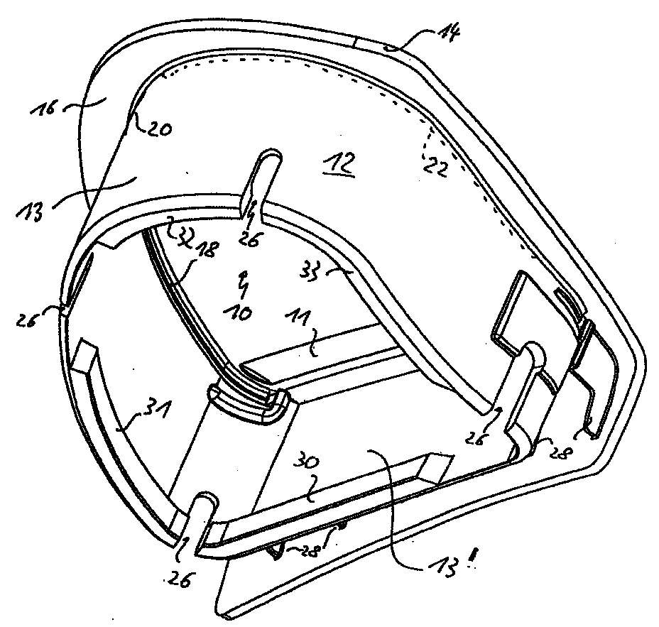
- the figure shows a perspective view obliquely from below to an airbag cover according to the invention, the existing lamination is not shown.
- the airbag cover shown in the figure is in one piece made of plastic and consists of a cover plate 10, on the front of which the lamination is arranged and is at right angles from the back circumferential wall section 12 extends from the peripheral edge 14 of the cover plate 10 is spaced, that is, a circumferential web portion 16 is formed, which over the Wall section 12 protrudes outwards.
- the wall section 12 has various mounting openings 26 (Slots) on, extending from the bottom of the wall section 12 extend upwards.
- the wall section 12 in plan view in essentially the shape of a "D", that is, the wall section 12 a curved section 13 and one has flat section 13 '.
- a material weakening near section 13 ' 11 provided that are substantially parallel extends to the flat portion 13 'and as a hinge for the cover plate 10 serves, which is explained in more detail below becomes.
- the cover plate 10 is outside the flat section 13 'of the wall section 12 angled downward and through webs 28 to the outside of the section 13 'connected.
- the invention Mount the airbag cover in the simplest way by this is placed on the airbag housing. With complete Put on the airbag cover, the elongated Projections 30, 31, 32 and 33 with the corresponding ones Fasteners on the airbag housing, resulting in a quick and simple assembly is guaranteed.
- predetermined breaking points 18, 22 On the inside of the wall section 12, namely on the Transitional area between the wall section 12 and the cover plate 10 there are two elongated predetermined breaking points 18, 22, each extending approximately from the flat section 13 ' of the curved section 13 extend so far that there is still a gap between them. Between these two internal predetermined breaking points 18 and 22 is on the Outside of the wall section 12 also in the edge between wall section 12 and cover plate 10 or web section 16 a further predetermined breaking point 20 is provided.
- the airbag cover shown in the figure is in one Vehicle mounted so that the inside of the cover folded airbag is located.
- the cover plate 10 in the area of the predetermined breaking points 18, 20, 22 from the wall section 12 blasted off, whereupon the cover plate 10 around material weakening 11 acting as a hinge upwards works. Since the predetermined breaking points 18, 20 and 22 in the transition area between the wall section 12 and the cover plate 10 are arranged and dimensioned accordingly are left when the cover plate is blown off 10 the web section 16 in one piece on the cover plate 10 and not on the wall section 12. That area of the Cover plate 10, which is beyond the material weakening 11 is located and around the flat section 13 'of the wall section 12 has moved around, remains in one piece on the Wall section 12.
- the cover plate 10 can easily with a lamination be made of fabric, plastic or leather, which are then preferably guided around the web section 16 and also attached to the underside of the web portion 16 is.
- a lamination affects the opening behavior the airbag cover not because it doesn't have one of the predetermined breaking points 18, 20, 22 also extends and the bending process in the area of material weakening 11 practical no opposition.
- the lamination points So no predetermined breaking point itself and must be removed from the cover plate not be pierced.
- the predetermined breaking points of the airbag cover according to the invention can either completely in the wall section 12 or in Transition area, that is in the edge between the Wall section 12 and the cover plate 10 may be provided. It is also possible to use the predetermined breaking point exclusively in to provide the cover plate 10. In this case, however the depth of the material weakening and the orientation of the Material weakening should be chosen so that the one to be blasted off Area of the cover plate together with the this area adjoining the web section from the wall section solves.
- the projecting web section 16 must be not completely, that is, over the entire scope, of loosen the wall section 12. Rather, it is sufficient that the web portion 16 together with the cover plate 10 solves only in the area that is responsible for the proper Unfolding the airbag is sufficient and necessary is.
- the airbag cover according to the invention can be with the help the basically already known low pressure technology advantageous already laminated by lamination, which need not be provided with a tear seam, in an injection mold is inserted. After closing the mold and injecting plastic material under pressure into the Form and after cooling accordingly the injection mold be opened and the already laminated cover can be removed from the mold.
- This way of making is only due to the airbag cover according to the invention reasonable effort has become possible since the lamination does not have to be provided with a tear seam and therefore does not have to be aligned in the form.
- the injection mold can be modified that the turning over and sticking of the handled Area of the lamination automatically afterwards to the injection molding process. But it is also possible to put the airbag cover on after spraying the lamination with the overhang that has not yet been turned over Take the edge out of the injection mold and turn it over and sticking the protruding edge of the lamination the rear of the web portion 16 by hand.
- the circumferential wall section 12 of the airbag cover according to the invention extends substantially perpendicular to the cover plate 10, but need not necessarily be complete circulate closed.
- the mounting slots shown 26 can also further interruptions or the like be provided, for example in a housing of the gas generator or the like engages.
- the circumferential wall section 12 in individual webs resolve that with the corresponding predetermined breaking points are provided. In this case too, the range should be between the webs through another component or housing part getting closed.
- the airbag cover according to the invention can be used particularly advantageously in a side airbag. However, any other application, for example in a leather-covered steering wheel or the like possible.
Landscapes
- Engineering & Computer Science (AREA)
- Mechanical Engineering (AREA)
- Air Bags (AREA)
- Injection Moulding Of Plastics Or The Like (AREA)
Abstract
Eine Airbagabdeckung besteht aus einer kaschierten Abdeckplatte
(10), an deren Rückseite ein umlaufender Wandabschnitt
(12) angeordnet ist, der von dem Umfangsrand (14)
der Abdeckplatte beabstandet ist, wodurch ein vorstehender
Stegabschnitt (16) gebildet ist. An dem Wandabschnitt (12)
und/oder der Abdeckplatte (16) sind mehrere Sollbruchstellen
(18, 20, 22) derart angeordnet, daß sich bei Entfalten
des Airbags die Abdeckplatte (10) zusammen mit ihrem Stegabschnitt
(16) von dem Wandabschnitt (12) löst.
Description
Die vorliegende Erfindung betrifft eine Airbagabdeckung nach dem Oberbegriff des Anspruchs 1. Derartige Airbagabdeckungen sind grundsätzlich bekannt und dienen dazu, den Luftsack des Airbags zusammen mit dem zugehörigen Gasgenerator formschön nach außen abzudecken. Damit sich die Airbagabdeckung bei Zünden des Gasgenerators und dem darauffolgenden Entfalten des Luftsacks öffnet, ist mindestens eine Sollbruchstelle an der Airbagabdeckung vorgesehen, an der die Airbagabdeckung aufgrund des hohen Drucks birst und sich öffnet.The present invention relates to an airbag cover according to the preamble of claim 1. Such airbag covers are generally known and serve to Airbag of the airbag together with the associated gas generator cover elegantly to the outside. So that the airbag cover when igniting the gas generator and the following one Unfolding the airbag opens at least a predetermined breaking point is provided on the airbag cover which bursts the airbag cover due to the high pressure and opens up.
In manchen Fällen kann es erforderlich sein, die Airbagabdeckung beispielsweise mit Stoff oder Leder zu kaschieren, damit diese an die Einbauumgebung angepaßt wird. In diesen Fällen wurde bislang vorgeschlagen, die Kaschierung, das heißt die Stoff- oder Lederbespannung im Bereich der Abdeckplatte ebenfalls mit einer Sollbruchstelle (Reißnaht) zu versehen, damit sich diese bei Zünden des Gasgenerators zuverlässig öffnet. Aufgrund der bestehenden Sicherheits- und Prüfvorschriften bringt dies jedoch erhebliche Nachteile mit sich, da in diesem Fall für jede unterschiedliche Kaschierung, das heißt für jeden unterschiedlichen Farb- und/oder Stoff- bzw. Ledertyp ein protokollierter Testversuch durchgeführt werden muß. Aufgrund der heutzutage üblichen Typen- und Farbenvielfalt kann dies für einen bestimmten Fahrzeugtyp bis zu 350 verschiedene Testversuche erfordern. In some cases, the airbag cover may be required for example to hide with fabric or leather, so that it is adapted to the installation environment. In these Cases have so far been suggested, lamination, that is the name of the fabric or leather covering in the area of the cover plate also with a predetermined breaking point (tear seam) to be provided so that this is when the gas generator is ignited opens reliably. Due to the existing security and However, test regulations have considerable disadvantages with itself because in this case for each different Lamination, that means for each different color and / or Material or leather type a logged test attempt must be carried out. Because of the usual nowadays Variety of types and colors can do this for a particular Vehicle type require up to 350 different test attempts.
Sofern die Airbagabdeckung nicht selbst mit einer Kaschierung versehen ist, sondern unter einer Sitzbespannung oder dergleichen eingebaut wird, ergibt sich der weitere Nachteil, daß der Sitz erst dann mit der Bespannung versehen werden kann, nachdem die Airbagabdeckung in diesen eingebaut ist. Dies bringt ebenfalls Produktionsnachteile mit sich.Unless the airbag cover itself with a lamination is provided, but under a seat covering or is installed, there is the further disadvantage that the seat is only then provided with the covering after the airbag cover is installed in it is. This also has production disadvantages yourself.
Es ist deshalb das der vorliegenden Erfindung zugrundeliegende Problem (Aufgabe), eine Airbagabdeckung nach dem Oberbegriff des Anspruchs 1 zu schaffen, die in Hinblick auf die oben erwähnten Probleme kostengünstiger hergestellt und eingebaut werden kann.It is therefore the basis of the present invention Problem (task), an airbag cover after the Preamble of claim 1 to create the in view made to the above-mentioned problems more cheaply and can be installed.
Die Lösung dieser Aufgabe erfolgt durch die Merkmale des Anspruchs 1 und insbesondere dadurch, daß die Sollbruchstelle an dem Wandabschnitt und/oder der Abdeckplatte derart angeordnet und dimensioniert ist, daß sich bei Entfalten des Airbags die Abdeckplatte zusammen mit ihrem Stegabschnitt zumindest teilweise von dem Wandabschnitt löst, und daß die Abdeckplatte mit einer Kaschierung versehen ist, die keine Sollbruchstelle aufweist.This problem is solved by the features of Claim 1 and in particular in that the predetermined breaking point on the wall section and / or the cover plate in such a way is arranged and dimensioned so that when unfolded of the airbag, the cover plate together with its web section at least partially detaches from the wall section, and that the cover plate is provided with a lamination, that has no predetermined breaking point.
Erfindungsgemäß öffnet sich die Abdeckplatte somit nicht mehr innerhalb des Wandabschnitts. Vielmehr löst sich die Abdeckplatte zusammen mit ihrem zugehörigen Stegabschnitt von dem Wandabschnitt. Hierdurch ist es möglich, die Kaschierung an der Abdeckplatte vorzusehen, wobei die Kaschierung keinerlei Sollbruchstellen bzw. Reißnähte aufweisen muß. Da sich bei der erfindungsgemäßen Airbagabdeckung die Abdeckplatte zusammen mit der darauf befindlichen Kaschierung öffnet, ist das Öffnungsverhalten der Airbagabdeckung unabhängig von der gewählten Kaschierung. Hierdurch können die erforderlichen Testversuche auf einige wenige Kaschierungen beschränkt werden, da beispielsweise die Verwendung eines gleichen Kaschierungsstoffes mit lediglich unterschiedlicher Farbgebung das Öffnungsverhalten der Airbagabdeckung nicht beeinflußt. Falls die erfindungsgemäße Airbagabdeckung in einem Fahrzeugsitz eingebaut wird, kann dies nach vollständiger Montage bzw. Herstellung des Sitzes erfolgen. Hierdurch ist die Fertigung des Fahrzeugsitzes nicht mehr von dem Einbau der Airbagabdeckung abhängig.According to the invention, the cover plate does not open more inside the wall section. Rather, it resolves Cover plate together with its associated web section from the wall section. This makes it possible to To provide lamination on the cover plate, the Lamination has no predetermined breaking points or tear seams got to. Since in the airbag cover according to the invention the cover plate together with the one on it Laminating opens, is the opening behavior of the airbag cover regardless of the chosen lamination. Hereby can do the necessary test trials on a few Laminations are limited, for example, the use the same lamination fabric with only different colors the opening behavior of the airbag cover unaffected. If the invention Airbag cover can be installed in a vehicle seat this after complete assembly or manufacture of the seat respectively. This is the manufacture of the vehicle seat no longer depends on the installation of the airbag cover.
Vorteilhafte Ausführungsformen der Erfindung sind in der Beschreibung, den Zeichnungen sowie den Unteransprüchen beschrieben.Advantageous embodiments of the invention are in the Description, the drawings and the subclaims described.
Nach einer ersten vorteilhaften Ausführungsform ist die Kaschierung auch an der Unterseite des Stegabschnitts befestigt. Diese Ausführungsform besitzt den Vorteil, daß sich die Kaschierung um den Stegabschnitt umlegen und an dessen Unterseite befestigen läßt, wodurch sich ein ansprechendes Äußeres ergibt.According to a first advantageous embodiment, the Lamination also attached to the underside of the web section. This embodiment has the advantage that fold the lamination around the web section and on it Bottom can be attached, making an appealing Outside results.
Nach einer weiteren Ausführungsform der Erfindung kann die Sollbruchstelle an dem Wandabschnitt oder in dem Übergangsbereich zwischen dem Wandabschnitt und der Abdeckplatte angeordnet sein. Grundsätzlich ist es auch möglich, die Sollbruchstelle in der Abdeckplatte vorzusehen, solange die als Sollbruchstelle vorgesehene Materialschwächung so dimensioniert und orientiert ist, daß sich der Stegabschnitt der Abdeckplatte zusammen mit der Abdeckplatte selbst von dem Wandabschnitt löst, wenn der Gasgenerator gezündet wird.According to a further embodiment of the invention, the Predetermined breaking point on the wall section or in the transition area arranged between the wall section and the cover plate be. In principle, it is also possible to use the predetermined breaking point to be provided in the cover plate as long as the The intended weakening point is dimensioned in this way and is oriented that the web section of the Cover plate together with the cover plate itself from that Wall section releases when the gas generator is ignited.
Nach einer weiteren Ausbildung der Erfindung ist die Sollbruchstelle an der Innenseite und/oder an der Außenseite des Wandabschnitts angeordnet. Auf diese Weise ist besonders gut sichergestellt, daß der Stegabschnitt nicht an dem Wandabschnitt verbleibt, sondern sich zusammen mit der Abdeckplatte von dem Wandabschnitt löst. Die Sollbruchstelle kann ausschließlich an der Innenseite des Wandabschnitts vorgesehen sein, kann sich jedoch auch teilweise oder insgesamt an der Außenseite des Wandabschnitts befinden. Ein abwechselndes Vorsehen von Sollbruchstellen an der Innenseite und der Außenseite des Wandabschnittes kann bei der Herstellung, das heißt beim Anfertigen der Preßform zu Vorteilen führen.According to a further embodiment of the invention, the predetermined breaking point on the inside and / or on the outside arranged of the wall section. This way is special well ensured that the web section is not on the Wall section remains, but together with the cover plate detaches from the wall section. The predetermined breaking point can only be on the inside of the wall section can be provided, but can also be partial or total located on the outside of the wall section. A alternating provision of predetermined breaking points on the inside and the outside of the wall section can Manufacturing, that is to say, advantages when manufacturing the mold to lead.
Ein besonders vorteilhaftes Verfahren zum Herstellen einer erfindungsgemäßen Airbagabdeckung besteht darin, daß zunächst die gewünschte Kaschierung der Airbagabdeckung in eine Spritzgußform eingelegt wird und anschließend Material unter Druck in die Form eingespritzt wird. Nach Öffnen der Form kann die vollständig kaschierte Airbagabdeckung aus der Spritzgußform entnommen werden. In Verbindung mit der erfindungsgemäßen Airbagabdeckung bietet dieses Verfahren besondere Vorteile, da die Kaschierung nicht mit einer Sollbruchstelle versehen ist und somit weder speziell präpariert werden muß, noch in der Spritzgußform ausgerichtet werden muß. Somit wird diese Verfahrensweise erst durch das Vorsehen der erfindungsgemäßen Airbagabdeckung möglich.A particularly advantageous method of making one Airbag cover according to the invention is that first the desired lamination of the airbag cover in an injection mold is inserted and then material is injected into the mold under pressure. After opening the The fully laminated airbag cover can take shape be taken from the injection mold. In connection with the Airbag cover according to the invention offers this method special advantages, since the lamination is not with a Predetermined breaking point is provided and therefore neither specially prepared must still be aligned in the injection mold must become. So this procedure is only through the Provision of the airbag cover according to the invention possible.
Nachfolgend wird die vorliegende Erfindung rein beispielhaft anhand einer vorteilhaften Ausführungsform und unter Bezugnahme auf die beigefügte Zeichnung beschrieben.In the following, the present invention becomes purely exemplary based on an advantageous embodiment and under Described with reference to the accompanying drawing.
Die Figur zeigt eine perspektivische Ansicht von schräg unten auf eine Airbagabdeckung gemäß der Erfindung, wobei die vorhandene Kaschierung nicht dargestellt ist.The figure shows a perspective view obliquely from below to an airbag cover according to the invention, the existing lamination is not shown.
Die in der Figur dargestellte Airbagabdeckung ist einstückig
aus Kunststoff hergestellt und besteht aus einer Abdeckplatte
10, an deren Vorderseite die Kaschierung angeordnet
ist und von deren Rückseite sich rechtwinklig ein
umlaufender Wandabschnitt 12 erstreckt, der vom Umfangsrand
14 der Abdeckplatte 10 beabstandet ist, das heißt, daß ein
umlaufender Stegabschnitt 16 gebildet ist, der über den
Wandabschnitt 12 nach außen vorsteht.The airbag cover shown in the figure is in one piece
made of plastic and consists of a cover plate
10, on the front of which the lamination is arranged
and is at right angles from the back
Der Wandabschnitt 12 weist verschiedene Montageöffnungen 26
(Schlitze) auf, die sich vom unteren Rand des Wandabschnitts
12 nach oben erstrecken. Bei dem dargestellten Ausführungsbeispiel
besitzt der Wandabschnitt 12 in der Draufsicht im
wesentlichen die Form eines "D", das heißt, daß der Wandabschnitt
12 einen gekrümmt verlaufenden Abschnitt 13 und einen
ebenen Abschnitt 13' aufweist. An der Unterseite der
Abdeckplatte 10 ist nahe dem Abschnitt 13' eine Materialschwächung
11 vorgesehen, die sich im wesentlichen parallel
zu dem ebenen Abschnitt 13' erstreckt und als Scharnier für
die Abdeckplatte 10 dient, was nachfolgend noch genauer erläutert
wird. Ferner ist die Abdeckplatte 10 außerhalb des
ebenen Abschnitts 13' des Wandabschnitts 12 nach unten abgewinkelt
und durch Stege 28 mit der Außenseite des Abschnitts
13' verbunden.The
Am unteren Rand des ebenen Abschnitts 13' ist ein länglicher
Vorsprung 30 und am unteren Rand des Wandabschnitts 12
sind drei weitere längliche Vorsprünge 31, 32 und 33 vorgesehen.
Sämtliche Vorsprünge sind einstückig mit dem Wandabschnitt
12 bzw. dem ebenen Abschnitt 13' ausgebildet und
dienen dazu, die Airbagabdeckung auf dem zugehörigen Unterteil
aufzubringen. Durch entsprechende Befestigungsmittel
am Unterteil des Airbaggehäuses läßt sich die erfindungsgemäße
Airbagabdeckung auf einfachste Weise montieren, indem
diese auf das Airbaggehäuse aufgesetzt wird. Bei vollständigem
Aufsetzen der Airbagabdeckung verrasten die länglichen
Vorsprünge 30, 31, 32 und 33 mit den entsprechenden
Befestigungsmitteln am Airbaggehäuse, wodurch eine schnelle
und einfache Montage gewährleistet ist. At the bottom of the flat section 13 'is an elongated one
An der Innenseite des Wandabschnitts 12, und zwar an dem
Übergangsbereich zwischen dem Wandabschnitt 12 und der Abdeckplatte
10 befinden sich zwei längliche Sollbruchstellen
18, 22, die sich jeweils etwa vom ebenen Abschnitt 13' entlang
des gekrümmten Abschnittes 13 soweit erstrecken, daß
noch ein Abstand zwischen ihnen verbleibt. Zwischen diesen
beiden innenliegenden Sollbruchstellen 18 und 22 ist an der
Außenseite des Wandabschnitts 12 ebenfalls in der Kante
zwischen Wandabschnitt 12 und Abdeckplatte 10 bzw. Stegabschnitt
16 eine weitere Sollbruchstelle 20 vorgesehen.On the inside of the
Die in der Figur dargestellte Airbagabdeckung wird in einem
Fahrzeug so montiert, daß sich innerhalb der Abdeckung der
zusammengefaltete Luftsack befindet. Bei Zünden des mit dem
Luftsack verbundenen Gasgenerators wird das Innere des
Luftsacks unter hohen Druck gesetzt, wodurch sich der Luftsack
zunächst innerhalb der Airbagabdeckung entfaltet.
Nachdem der Innendruck innerhalb des Luftsacks einen bestimmten
Wert überschritten hat, wird die Abdeckplatte 10
im Bereich der Sollbruchstellen 18, 20, 22 von dem Wandabschnitt
12 abgesprengt, worauf die Abdeckplatte 10 um die
als Scharnier wirkende Materialschwächung 11 nach oben
klappt. Da erfindungsgemäß die Sollbruchstellen 18, 20 und
22 im Übergangsbereich zwischen dem Wandabschnitt 12 und
der Abdeckplatte 10 angeordnet sind und entsprechend dimensioniert
sind, verbleibt beim Absprengen der Abdeckplatte
10 der Stegabschnitt 16 einstückig an der Abdeckplatte 10
und nicht an dem Wandabschnitt 12. Derjenige Bereich der
Abdeckplatte 10, der sich jenseits der Materialschwächung
11 befindet und der um den ebenen Abschnitt 13' des Wandabschnitts
12 herumgezogen ist, verbleibt einstückig an dem
Wandabschnitt 12. The airbag cover shown in the figure is in one
Vehicle mounted so that the inside of the cover
folded airbag is located. When igniting the with the
Airbag connected gas generator is the inside of the
Air bags put under high pressure, causing the air bag to become
first deployed inside the airbag cover.
After the internal pressure within the airbag a certain
Has exceeded the value, the cover plate 10
in the area of the
Die Abdeckplatte 10 kann auf einfache Weise mit einer Kaschierung
aus Stoff, Kunststoff oder Leder versehen werden,
die dann vorzugsweise um den Stegabschnitt 16 herumgeführt
und auch an der Unterseite des Stegabschnitts 16 befestigt
ist. Eine derartige Kaschierung beeinträchtigt das Öffnungsverhalten
der Airbagabdeckung nicht, da sie nicht über
eine der Sollbruchstellen 18, 20, 22 hinaus erstreckt und
den Biegevorgang im Bereich der Materialschwächung 11 praktisch
kein Widerstand entgegensetzt. Die Kaschierung weist
also selbst keine Sollbruchstelle auf und muß von der Abdeckplatte
nicht durchstoßen werden.The cover plate 10 can easily with a lamination
be made of fabric, plastic or leather,
which are then preferably guided around the
Die Sollbruchstellen der erfindungsgemäßen Airbagabdeckung
können entweder vollständig im Wandabschnitt 12 oder im
Übergangsbereich, das heißt in der Kante zwischen dem
Wandabschnitt 12 und der Abdeckplatte 10 vorgesehen sein.
Auch ist es möglich, die Sollbruchstelle ausschließlich in
der Abdeckplatte 10 vorzusehen. In diesem Fall muß jedoch
die Tiefe der Materialschwächung und die Orientierung der
Materialschwächung so gewählt werden, daß sich der abzusprengende
Bereich der Abdeckplatte zusammen mit dem an
diesen Bereich angrenzenden Stegabschnitt von dem Wandabschnitt
löst. Der vorstehende Stegabschnitt 16 muß sich
nicht vollständig, das heißt über den gesamten Umfang, von
dem Wandabschnitt 12 lösen. Vielmehr ist es ausreichend,
daß sich der Stegabschnitt 16 zusammen mit der Abdeckplatte
10 nur in demjenigen Bereich löst, der für das ordnungsgemäße
Entfalten des Luftsacks ausreichend und erforderlich
ist.The predetermined breaking points of the airbag cover according to the invention
can either completely in the
Die erfindungsgemäße Airbagabdeckung läßt sich mit Hilfe der grundsätzlich bereits bekannten Niederdrucktechnik vorteilhaft bereits kaschiert herstellen, indem die Kaschierung, die nicht mit einer Reißnaht versehen sein muß, in eine Spritzgußform eingelegt wird. Nach Schließen der Form und Einspritzen von Kunststoffmaterial unter Druck in die Form und nach entsprechendem Abkühlen kann die Spritzgußform geöffnet werden und die bereits kaschierte Abdeckung kann aus der Form entnommen werden. Diese Herstellungsweise ist erst aufgrund der erfindungsgemäßen Airbagabdeckung mit vertretbarem Aufwand möglich geworden, da die Kaschierung nicht mit einer Reißnaht versehen werden muß und demnach nicht in der Form entsprechend ausgerichtet werden muß.The airbag cover according to the invention can be with the help the basically already known low pressure technology advantageous already laminated by lamination, which need not be provided with a tear seam, in an injection mold is inserted. After closing the mold and injecting plastic material under pressure into the Form and after cooling accordingly the injection mold be opened and the already laminated cover can be removed from the mold. This way of making is only due to the airbag cover according to the invention reasonable effort has become possible since the lamination does not have to be provided with a tear seam and therefore does not have to be aligned in the form.
Sofern in bevorzugter Weise die Kaschierung seitlich über
die Abdeckplatte 10 vorsteht und nach unten um den Stegabschnitt
16 umgeschlagen wird, kann die Spritzgußform so modifiziert
werden, daß das Umschlagen und Festkleben des umgeschlagenen
Bereichs der Kaschierung automatisch im Anschluß
an den Spritzgußformvorgang erfolgt. Es ist aber
auch möglich, die Airbagabdeckung nach dem Aufspritzen auf
die Kaschierung mit noch nicht umgeschlagenem überstehenden
Rand aus der Spritzgußform zu entnehmen und das Umschlagen
und Festkleben des überstehenden Randes der Kaschierung an
der Rückseite des Stegabschnitts 16 von Hand vorzunehmen.If preferred, the lamination laterally over
the cover plate 10 protrudes and down around the
Eine dritte Möglichkeit der Anbringung der Kaschierung besteht
darin, daß zunächst die Airbagabdeckung ohne Kaschierung
in der Spritzgußform vollständig hergestellt und die
Kaschierung erst anschließend von Hand oder durch eine geeignete
Vorrichtung aufgebracht und der überstehende Rand
um den Stegabschnitt 16 herumgeschlagen und dort befestigt
wird.There is a third possibility of attaching the lamination
in that first the airbag cover without lamination
completely manufactured in the injection mold and the
Only then lamination by hand or by a suitable
Device applied and the protruding edge
struck around the
Der umlaufende Wandabschnitt 12 der erfindungsgemäßen Airbagabdeckung
erstreckt sich im wesentlichen senkrecht zu
der Abdeckplatte 10, muß jedoch nicht unbedingt vollständig
geschlossen umlaufen. Neben den dargestellten Montageschlitzen
26 können auch weitere Unterbrechungen oder dergleichen
vorgesehen sein, in die beispielsweise ein Gehäuse
des Gasgenerators oder dergleichen eingreift. Auch ist es
möglich, den umlaufenden Wandabschnitt 12 in einzelne Stege
aufzulösen, die mit den entsprechenden Sollbruchstellen
versehen sind. Auch in diesem Fall müßte der Bereich zwischen
den Stegen durch ein anderes Bauteil oder Gehäuseteil
geschlossen werden. Die erfindungsgemäße Airbagabdeckung
läßt sich besonders vorteilhaft bei einem Seitenairbag einsetzen.
Jedoch ist auch jede andere Anwendung, beispielsweise
in einem lederkaschierten Lenkrad oder dergleichen
möglich. The
- 1010th
- AbdeckplatteCover plate
- 1212th
- WandabschnittWall section
- 1313
- gekrümmter Abschnittcurved section
- 13'13 '
- ebener Abschnittflat section
- 1414
- UmfangsrandPeripheral edge
- 1616
- StegabschnittWeb section
- 1818th
- SollbruchstellePredetermined breaking point
- 2020th
- SollbruchstellePredetermined breaking point
- 2222
- SollbruchstellePredetermined breaking point
- 2626
- MontageschlitzMounting slot
- 2828
- Stegweb
- 3030th
- Vorsprunghead Start
- 3131
- Vorsprunghead Start
- 3232
- Vorsprunghead Start
- 3333
- Vorsprunghead Start
Claims (6)
dadurch gekennzeichnet, daß
das Öffnungsverhalten der Airbagabdeckung unabhängig von einer auf der Abdeckplatte (10) aufgebrachten Kaschierung ist.Airbag cover, in particular for a side airbag, consisting of a cover plate (10), on the back of which a circumferential wall section (12) is arranged, which is spaced from the peripheral edge (14) of the cover plate (10), whereby a projecting web section (16) is formed at least one predetermined breaking point is provided for opening the airbag cover,
characterized in that
the opening behavior of the airbag cover is independent of a lamination applied to the cover plate (10).
dadurch gekennzeichnet, daß
die Sollbruchstelle (18, 20, 22) an dem Wandabschnitt (12) und/oder der Abdeckplatte (16) angeordnet und derart dimensioniert ist, daß sich bei Entfalten des Airbags die Abdeckplatte (10) zusammen mit ihrem Stegabschnitt (16) zumindest teilweise von dem Wandabschnitt (12) löst, und daß die Abdeckplatte (10) mit einer Kaschierung versehen ist, die keine Sollbruchstelle aufweist. Airbag cover according to claim 1,
characterized in that
the predetermined breaking point (18, 20, 22) is arranged on the wall section (12) and / or the cover plate (16) and is dimensioned such that when the airbag is deployed, the cover plate (10) together with its web section (16) at least partially the wall section (12), and that the cover plate (10) is provided with a lamination which has no predetermined breaking point.
dadurch gekennzeichnet, daß
die Kaschierung auch an der Unterseite des Stegabschnitts (16) befestigt ist.Airbag cover according to claim 1 or 2,
characterized in that
the lamination is also attached to the underside of the web section (16).
dadurch gekennzeichnet, daß
die Sollbruchstelle (18, 20, 22) an dem Wandabschnitt (12) oder in dem Übergangsbereich zwischen dem Wandabschnitt (12) und der Abdeckplatte (10) angeordnet ist.Airbag cover according to claim 1, 2 or 3,
characterized in that
the predetermined breaking point (18, 20, 22) is arranged on the wall section (12) or in the transition region between the wall section (12) and the cover plate (10).
dadurch gekennzeichnet, daß
die Sollbruchstelle (18, 20, 22) an der Innenseite und/oder an der Außenseite des Wandabschnitts (12) angeordnet ist.Airbag cover according to at least one of the preceding claims,
characterized in that
the predetermined breaking point (18, 20, 22) is arranged on the inside and / or on the outside of the wall section (12).
gekennzeichnet durch die folgenden Schritte:
characterized by the following steps:
Applications Claiming Priority (2)
| Application Number | Priority Date | Filing Date | Title |
|---|---|---|---|
| DE19730340 | 1997-07-15 | ||
| DE1997130340 DE19730340A1 (en) | 1997-07-15 | 1997-07-15 | Airbag cover |
Publications (2)
| Publication Number | Publication Date |
|---|---|
| EP0891900A2 true EP0891900A2 (en) | 1999-01-20 |
| EP0891900A3 EP0891900A3 (en) | 2000-04-12 |
Family
ID=7835796
Family Applications (1)
| Application Number | Title | Priority Date | Filing Date |
|---|---|---|---|
| EP98111285A Withdrawn EP0891900A3 (en) | 1997-07-15 | 1998-06-18 | Air bag cover |
Country Status (3)
| Country | Link |
|---|---|
| EP (1) | EP0891900A3 (en) |
| JP (1) | JPH1170847A (en) |
| DE (1) | DE19730340A1 (en) |
Families Citing this family (3)
| Publication number | Priority date | Publication date | Assignee | Title |
|---|---|---|---|---|
| JP4822777B2 (en) | 2005-09-07 | 2011-11-24 | タカタ株式会社 | Airbag device, motorcycle with airbag device |
| JP4702842B2 (en) * | 2006-02-14 | 2011-06-15 | 本田技研工業株式会社 | Airbag module for vehicles |
| DE102011122465B3 (en) | 2011-12-24 | 2013-02-28 | Autoliv Development Ab | Made of plastic covering element for a driver's gas bag module and cover consisting of such a cover and a coating arranged on this |
Family Cites Families (11)
| Publication number | Priority date | Publication date | Assignee | Title |
|---|---|---|---|---|
| JPH0428515A (en) * | 1990-05-24 | 1992-01-31 | Takata Kk | Method of molding module cover of air bag device |
| JPH0443145A (en) * | 1990-06-08 | 1992-02-13 | Takata Kk | Module cover for air bag device |
| KR920009637A (en) * | 1990-11-13 | 1992-06-25 | 다카다 쥬우이찌로오 | Molding method of module cover of airbag device |
| JP3165492B2 (en) * | 1992-01-30 | 2001-05-14 | マツダ株式会社 | Automotive airbag equipment |
| US5335935A (en) * | 1992-08-31 | 1994-08-09 | Plastic Mold Technology Incorporated | Air bag cover/molded article with integral cover layer of leather |
| US5348339A (en) * | 1992-10-30 | 1994-09-20 | Alliedsignal Inc. | Air bag module with cover |
| GB2279302B (en) * | 1993-06-21 | 1996-06-12 | Autoliv Dev | Improvements in or relating to a cover for an air-bag |
| US5378013A (en) * | 1993-08-06 | 1995-01-03 | Ford Motor Company | Cover retainer assembly for inflatable restraint air bag |
| JPH0899594A (en) * | 1994-09-29 | 1996-04-16 | Nippon Seiko Kk | Cover for airbag module |
| JPH08164814A (en) * | 1994-10-13 | 1996-06-25 | Sensor Technol Kk | Bag cover |
| ITMI950503A1 (en) * | 1995-03-16 | 1996-09-16 | Momo Spa | AIR CUSHION DEVICE FOR VEHICLE STEERING WHEEL |
-
1997
- 1997-07-15 DE DE1997130340 patent/DE19730340A1/en not_active Withdrawn
-
1998
- 1998-06-17 JP JP10169967A patent/JPH1170847A/en active Pending
- 1998-06-18 EP EP98111285A patent/EP0891900A3/en not_active Withdrawn
Also Published As
| Publication number | Publication date |
|---|---|
| JPH1170847A (en) | 1999-03-16 |
| EP0891900A3 (en) | 2000-04-12 |
| DE19730340A1 (en) | 1999-01-21 |
Similar Documents
| Publication | Publication Date | Title |
|---|---|---|
| DE19819573B4 (en) | dashboard | |
| DE69708536T2 (en) | Side impact airbag module with extruded lid | |
| DE69702676T2 (en) | Motor vehicle interior clothing | |
| DE60019472T2 (en) | Head-protecting airbag device | |
| DE102008021265A1 (en) | Motor vehicle with A-pillar and in this stored airbag | |
| DE60302804T2 (en) | Knee-protecting airbag device | |
| DE102017100330A1 (en) | Airbag assembly and method for its manufacture | |
| DE4139483C2 (en) | Gas bag | |
| DE102013014405B4 (en) | Trim panel for attachment to a vehicle body panel having an airbag module, airbag system having a body panel and such a trim panel, and method of making the trim panel | |
| EP1237764A1 (en) | Airbag system for motor vehicles integrated in an inner trim piece | |
| DE10297288T5 (en) | Tab for setting the Z height of an airbag module | |
| DE102014008973A1 (en) | Airbag module | |
| DE19752989A1 (en) | Side impact airbag for motor vehicles | |
| DE69412671T2 (en) | Airbag lid | |
| DE69602791T2 (en) | Manufacturing process for a cover | |
| DE202006009442U1 (en) | Cover unit for airbag, comprising decorative border and other areas created during production process | |
| EP3122598B1 (en) | Emblem for an airbag module, airbag module and steering wheel with such an airbag module | |
| EP2059417B1 (en) | Airbag covering | |
| EP1147949B1 (en) | Air bag module | |
| EP0891900A2 (en) | Air bag cover | |
| DE3808284C2 (en) | ||
| EP2558335B1 (en) | Airbag system and method for manufacturing the same | |
| DE29801871U1 (en) | Airbag module for a head protection airbag | |
| EP4297997A1 (en) | Airbag module cap for an airbag module of a vehicle, airbag module having the airbag module cap, vehicle having the airbag module and method for manufacturing an airbag module cap | |
| EP1033293B1 (en) | Cover for an airbag module |
Legal Events
| Date | Code | Title | Description |
|---|---|---|---|
| PUAI | Public reference made under article 153(3) epc to a published international application that has entered the european phase |
Free format text: ORIGINAL CODE: 0009012 |
|
| AK | Designated contracting states |
Kind code of ref document: A2 Designated state(s): AT BE CH CY DE DK ES FI FR GB GR IE IT LI LU MC NL PT SE |
|
| AX | Request for extension of the european patent |
Free format text: AL;LT;LV;MK;RO;SI |
|
| PUAL | Search report despatched |
Free format text: ORIGINAL CODE: 0009013 |
|
| AK | Designated contracting states |
Kind code of ref document: A3 Designated state(s): AT BE CH CY DE DK ES FI FR GB GR IE IT LI LU MC NL PT SE |
|
| AX | Request for extension of the european patent |
Free format text: AL;LT;LV;MK;RO;SI |
|
| AKX | Designation fees paid | ||
| REG | Reference to a national code |
Ref country code: DE Ref legal event code: 8566 |
|
| STAA | Information on the status of an ep patent application or granted ep patent |
Free format text: STATUS: THE APPLICATION IS DEEMED TO BE WITHDRAWN |
|
| 18D | Application deemed to be withdrawn |
Effective date: 20001013 |