EP0891929A2 - Screw closure with tamper indicating band - Google Patents
Screw closure with tamper indicating band Download PDFInfo
- Publication number
- EP0891929A2 EP0891929A2 EP98108918A EP98108918A EP0891929A2 EP 0891929 A2 EP0891929 A2 EP 0891929A2 EP 98108918 A EP98108918 A EP 98108918A EP 98108918 A EP98108918 A EP 98108918A EP 0891929 A2 EP0891929 A2 EP 0891929A2
- Authority
- EP
- European Patent Office
- Prior art keywords
- cap
- predetermined breaking
- breaking point
- tear
- guarantee band
- Prior art date
- Legal status (The legal status is an assumption and is not a legal conclusion. Google has not performed a legal analysis and makes no representation as to the accuracy of the status listed.)
- Granted
Links
- 230000000295 complement effect Effects 0.000 claims abstract description 41
- 230000002093 peripheral effect Effects 0.000 claims abstract description 22
- 239000011324 bead Substances 0.000 claims abstract description 15
- 239000000463 material Substances 0.000 claims abstract description 6
- 230000000694 effects Effects 0.000 description 3
- 230000014759 maintenance of location Effects 0.000 description 3
- 230000003313 weakening effect Effects 0.000 description 2
- 230000005540 biological transmission Effects 0.000 description 1
- 230000015572 biosynthetic process Effects 0.000 description 1
- 239000011521 glass Substances 0.000 description 1
- 230000003993 interaction Effects 0.000 description 1
- 238000000034 method Methods 0.000 description 1
- 230000002787 reinforcement Effects 0.000 description 1
- 230000000717 retained effect Effects 0.000 description 1
- 235000014214 soft drink Nutrition 0.000 description 1
- 230000007704 transition Effects 0.000 description 1
Images


Classifications
-
- B—PERFORMING OPERATIONS; TRANSPORTING
- B65—CONVEYING; PACKING; STORING; HANDLING THIN OR FILAMENTARY MATERIAL
- B65D—CONTAINERS FOR STORAGE OR TRANSPORT OF ARTICLES OR MATERIALS, e.g. BAGS, BARRELS, BOTTLES, BOXES, CANS, CARTONS, CRATES, DRUMS, JARS, TANKS, HOPPERS, FORWARDING CONTAINERS; ACCESSORIES, CLOSURES, OR FITTINGS THEREFOR; PACKAGING ELEMENTS; PACKAGES
- B65D41/00—Caps, e.g. crown caps or crown seals, i.e. members having parts arranged for engagement with the external periphery of a neck or wall defining a pouring opening or discharge aperture; Protective cap-like covers for closure members, e.g. decorative covers of metal foil or paper
- B65D41/32—Caps or cap-like covers with lines of weakness, tearing-strips, tags, or like opening or removal devices, e.g. to facilitate formation of pouring openings
- B65D41/34—Threaded or like caps or cap-like covers provided with tamper elements formed in, or attached to, the closure skirt
- B65D41/3442—Threaded or like caps or cap-like covers provided with tamper elements formed in, or attached to, the closure skirt with rigid bead or projections formed on the tamper element and coacting with bead or projections on the container
- B65D41/3447—Threaded or like caps or cap-like covers provided with tamper elements formed in, or attached to, the closure skirt with rigid bead or projections formed on the tamper element and coacting with bead or projections on the container the tamper element being integrally connected to the closure by means of bridges
-
- B—PERFORMING OPERATIONS; TRANSPORTING
- B65—CONVEYING; PACKING; STORING; HANDLING THIN OR FILAMENTARY MATERIAL
- B65D—CONTAINERS FOR STORAGE OR TRANSPORT OF ARTICLES OR MATERIALS, e.g. BAGS, BARRELS, BOTTLES, BOXES, CANS, CARTONS, CRATES, DRUMS, JARS, TANKS, HOPPERS, FORWARDING CONTAINERS; ACCESSORIES, CLOSURES, OR FITTINGS THEREFOR; PACKAGING ELEMENTS; PACKAGES
- B65D2401/00—Tamper-indicating means
- B65D2401/15—Tearable part of the closure
- B65D2401/30—Tamper-ring remaining connected to closure after initial removal
Definitions
- Guaranteed tape is designed so that it is the first time Opening in the right place tears, but that later Resealing the container mouth the closing process does not bother.
- This task is largely solved by the Screw cap according to EP 0 371 920 B1. It has been shown that it is sufficient to have the guarantee band over a predetermined Circumferential section in one piece and firmly with the lower edge of the cap to connect, this section primarily only supporting and Retention function and a symmetrical fitting of the cap on the bottle. The actual guarantee function is, however, taken over by the remaining part of the guarantee band, the when unscrewing the cap from the lower edge of the cap for the first time tears off.
- the present invention is therefore based on the object to improve a screw cap of the type mentioned at the beginning, that when unscrewing for the first time the tear-off force over the Cross-section of the predetermined breaking point integrated in the guarantee band is equally effective.
- the predetermined breaking point runs obliquely to the vertical.
- the angle at which the predetermined breaking point is relative to Vertical stretches, the angle at which the The predetermined breaking point is the second one that can be torn off the cap Complementary section of the guarantee tape when torn from the first, with the cap tear-proof peripheral portion of the Guarantee band relative to the horizontal or circumferential direction extends. Then it is ensured that the tear-off force over the entire cross section or the entire length of the predetermined breaking point or across the entire width of the guarantee band at the Predetermined breaking point is equally effective. It is then ensures that the guarantee tape extends across the entire width the predetermined breaking point tears, so that the desired Guarantee function is fulfilled.
- the angle at which the predetermined breaking point is relative to Vertical stretching is about 5 to 20 degrees, in particular about 10 to 15 degrees.
- the vertical is by the direction of the Screw cap center axis defined.
- the horizontal is determined by the level at which the guarantee band extends.
- the predetermined breaking point preferably comprises an in Circumferential tearable web, especially a lower one a bridge near the edge and an upper bridge that is close to the lower one Edge of the cap extends. These bridges bridge you over Cut across the entire width of the guarantee band. This incision is preferably delimited by a vertical cutting line on the second one that can be torn off the cap Complementary section of the guarantee band and an oblique to Vertical cutting line at the first, with the cap tear-proof circumferential section of the guarantee band.
- the cap tearable complementary section is shorter than that with the Cap firmly connected section of the guarantee band.
- a second predetermined breaking point between the two guarantee tape sections provided that the when screwing on for the first time of the cap required stretch of the guarantee band in Guaranteed circumferential direction.
- this second predetermined breaking point is on Claim 13 referred.
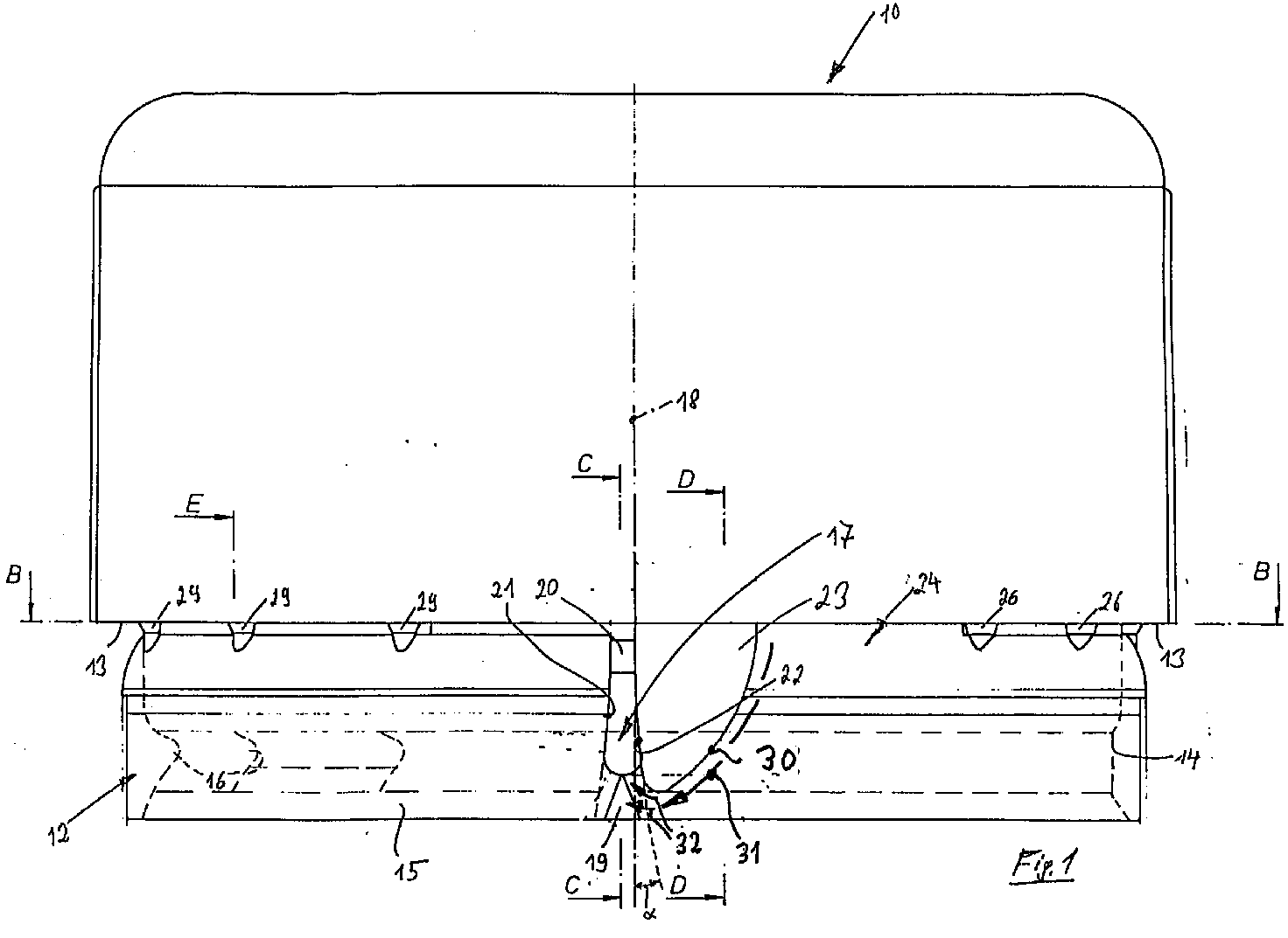
- FIGS 1 to 3 show a screw cap 10
- Plastic material with an internal thread 11 intended for this is a container mouth with a complementary external thread to close.
- Such screw caps are particularly for closing bottles with soft drinks or the like used, which is usually Reusable glass bottles with a standardized bottle mouth acts.
- the screw cap 10 includes a guarantee band 12.
- the first peripheral portion 14 connected to the cap so as to be tear-proof the guarantee band 12 is the same in the circumferential direction a first one that can be torn open when the cap is unscrewed for the first time
- This predetermined breaking point 17th 1 runs very well to the vertical 18 aslant. Specifically, this is the first predetermined breaking point by one Incision defined by a lower margin Tear-off web 19 and an upper one, located near the lower edge of the Cap extending tear-off web 20 is bridged.
- the Wall thickness of these tear-off webs 19 and 20 is in relation to Wall thickness of the guarantee tape, by the way, significantly lower.
- the predetermined breaking point defining incision is limited by an almost vertically extending section line 21 at the second, - of the cap tearable complementary section 15 of the guarantee tape 12 and a cutting line 22 running obliquely to the vertical 18 first circumferential section 14 connected to the cap so as to be tear-proof of the guarantee band 12.
- the directly to the so defined Predetermined breaking point 17 adjacent area 23 of the first, with the Cap tear-proof peripheral portion 14 of the Guarantee band 12 is additionally reinforced.
- This area has a larger wall thickness in comparison, in particular a wall thickness corresponding to the cap wall thickness. this applies especially for the transition area between them Area of the guarantee band and the lower edge 13 of the Screw cap 10. So it should be ensured that this Area 23 of the guarantee tape firmly with the lower edge 13 of the Screw cap 10 is connected and also remains connected before especially when you first unscrew the cap 10.
- Section line 22 extends at an angle ⁇ relative to Vertical 18, which corresponds to the angle at which the The predetermined breaking point 17 is the second one that can be torn off the cap Complementary section 15 of the guarantee tape 12 when torn off first circumferential section 14 connected to the cap so as to be tear-proof of the guarantee band 12 relative to the horizontal or
- connection between the complementary section 15 and the tear-resistant with the Screw cap connected peripheral portion 14 of the guarantee tape 12 remains initially with the consequence that when first Unscrew the screw cap from the lower edge 13 of the same separated complementary section 15 of the guarantee band 12 after tilts down, around a kind of hinge defining predetermined breaking point 17.
- the complementary section 15 The guarantee band 12 closes a sharp in this position Angle with the lower edge 13 of the screw cap 10. At the Demolition of the complementary section 15 from that with the Screw cap 10 fixedly connected first peripheral portion 14 of the Guarantee tape 12 corresponds to this angle approximately the angle ⁇ the section line 22, the effective course of the Predetermined breaking point 17 defined relative to the vertical 18.
- the tear-off webs 19, 20 of the predetermined breaking point 17 approximately perpendicular to the cutting line 22 or perpendicular to the oblique Course of the predetermined breaking point 17. This ensures that the tear of the guarantee tape in the circumferential direction of the same the predetermined breaking point 17 over the entire width of the Guarantee band is made uniformly. It will ensured that both the upper tear-off web 20 and the break lower tear-off bar 19; because, for example, only that would lower tear-off bar 19 near the edge when unscrewing the first time Tear off the cap, it would be conceivable that the retaining rib 16 overcomes the complementary ring bead at the container opening, without the upper tear-off web 20 tearing.
- the mentioned angle ⁇ between the vertical 18 and the Section line 22, which is the oblique course of the predetermined breaking point 17th defined is about 5 to 20 degrees, especially about 10 to 15 degrees, specifically 10 degrees here.
- the predetermined breaking point 12 can also be cut through an appropriately trained notch or material weakening be defined, which extends over the entire width of the Guarantee band 12 extends. At least one boundary line this notch or material weakening then extends in the Angle ⁇ , d. H. at an angle to the vertical 18.
- the tear-resistant connection between the first peripheral section 14 of the guarantee band 12 takes place in the illustrated Embodiment by a directly to the predetermined breaking point 17 adjacent over a predetermined angle of at least 15 degrees, here about 40 degrees continuously with the lower one Cap edge 13 connected connecting portion 24,
- the above already mentioned reinforcement area 23 includes, at least one, here three approximately diametrically to the connecting section 24 trained connecting webs 25 with one of the cap wall thickness corresponding wall thickness and a predetermined extent circumferentially over at least 5 to 10 degrees, and by several circumferentially formed between them Connecting webs 26 spaced uniformly from one another reduced wall thickness.
- the first, tearproof with the cap 10 connected peripheral portion 14 of the guarantee tape 12 extends in the illustrated embodiment over an angle of more than 180 degrees, especially about 210 degrees.
- This first one Circumferential portion 14 is from the second, tearable from the cap Complementary section 15 of the guarantee band 12 by a second, the first predetermined breaking point 17 approximately opposite arranged predetermined breaking point 27 separately.
- This second The predetermined breaking point is somewhat more tear-resistant in the circumferential direction designed as the first predetermined breaking point 17; the second Breakage point 27 is intended for the consumer after the first time Unscrew the screw cap 10 the complete removal of the Complementary section 15 of the screw cap 10 and the first, firmly connected to the screw cap 10 Lighten circumferential section 14 of the guarantee band 12.
- the second predetermined breaking point 27 is also through an incision defined (see Fig. 6), the edge of a tearable web 28 is bridged.
- the web 28 is formed on the inside in the form of a groove, in order to achieve this To tear off the complementary section 15 easier.
- the the second predetermined breaking point 27 extending incision preferably across the entire width of the guarantee band. In the embodiment according to FIG. 6, the mentioned incision starting from the bottom of the Guarantee band 12 only about 3/4 of the width of the Guarantee band 12.
- the connection between the guarantee band 12 and the lower edge 13 of the screw cap 10 in the area of second predetermined breaking point 27 is then preferably so trained as the connection of the tear-off webs between the Complementary section 15 of the guarantee band 12 and the lower Edge 13 of the screw cap 10.
- the tear-off webs mentioned between the lower edge 13 of the screw cap 10 and the Complementary section 15 of the guarantee band 12 are with the Reference numbers 29 marked.
- the angle between this section line 21 and the Vertical 18 is preferably slightly less than the angle ⁇ between the vertical 18 and the second cutting line 22, the to the tear-resistant peripheral portion 14 of the guarantee band 12 connects to the one desired above Get effect.
- the one that defines the predetermined breaking point 17 Incision tapers starting from this embodiment conical upwards from the lower edge of the guarantee band 12, especially asymmetrical conical.
- the arc line 30 is part of a parabola. Specifically, it sets in an angle of approximately 90 ° at the lower edge of the screw cap 10 or at the top of the guarantee band 12.
- the lower one lower tear-off web 19 is the end of the curved line 30 rounded and goes in the first, tear-resistant with the cap associated peripheral portion 14 of the guarantee band 12 associated lateral boundary (oblique section line 22) of the Predetermined breaking point 17 over.
- the above-described embodiment guarantees a when opening the screw cap 10 one Force transmission into the predetermined breaking point 17, in particular in the lower tear-off web 19 of the same, according to arrows 31, 32, i.e.
- the predetermined breaking line or tear line in the lower tear-off web 19 is usually the continuation of oblique cutting line 22, i.e. the one connected to the tearproof Section 14 of the guarantee band 12 associated lateral Limitation of the predetermined breaking point 17.
Landscapes
- Engineering & Computer Science (AREA)
- Mechanical Engineering (AREA)
- Closures For Containers (AREA)
- Golf Clubs (AREA)
Abstract
Schraubkappe (10) aus Kunststoffmaterial zum Verschließen einer
Behältermündung mit einem am unteren Rand (13) der Kappe
angeordneten und einstückig mit dieser ausgebildeten,
umlaufenden Garantieband (12). Das Garantieband ist dazu
bestimmmt, bei aufgesetzter Kappe (10) einen ringförmigen Wulst
an der Behältermündung zu untergreifen, wobei zu diesem Zweck
auf der Innenseite ein Rückhaltemittel (16) vorgesehen ist, das
beim erstmaligen Aufbringen der Kappe über den Wulst schiebbar
ist und in der Endposition der Kappe unter den Wulst einrastet.
Das Garantieband ist in einen ersten Umfangsabschnitt (14), der
reißfest mit der Kappe verbunden ist, sowie einen zweiten
Komplementärabschnitt (15) unterteilt, der von der Kappe
abreißbar ist. Zwischen diesen beiden Umfangsabschnitten ist
eine in Umfangsrichtung aufreißbare Sollbruchstelle (17)
ausgebildet, die beim ersten Abschrauben der Kappe reißen soll.
Diese Sollbruchstelle (17) verläuft schräg zur Vertikalen (18).
Description
Die Erfindung betrifft eine Schraubkappe aus Kunststoffmaterial zum Verschließen einer Behältermündung mit einem am unteren Rand der Kappe angeordneten und einstückig mit dieser ausgebildeten, umlaufenden Garantieband,
- das dazu bestimmt ist, bei aufgesetzter Kappe einen ringförmigen Wulst an der Behältermündung zu untergreifen, wobei zu diesem Zweck auf der Innenseite ein Rückhaltemittel vorgesehen ist, das beim erstmaligen Aufbringen, insbesondere Aufschrauben der Kappe über den Wulst schiebbar ist und in der Endposition der Kappe unter den Wulst einrastet, und
- das in einen ersten Umfangsschnitt, der reißfest mit der Kappe verbunden ist, sowie einen zweiten Komplementärabschnitt unterteilt ist, der von der Kappe abreißbar ist, wobei der erste mit der Kappe reißfest verbundene Umfangsabschnitt des Garantiebandes in Umfangsrichtung desselben über wenigstens eine beim erstmaligen Abschrauben der Kappe abreißbare Sollbruchstelle mit dem zweiten, von der Kappe abreißbaren Komplementärabschnitt verbunden ist.
- which is intended to grip under an annular bead at the container mouth when the cap is in place, for which purpose a retaining means is provided on the inside, which can be pushed over the bead when the cap is first applied, in particular when the cap is on, and in the end position of the cap underneath the bead engages, and
- which is subdivided into a first circumferential section, which is connected to the cap in a tear-resistant manner, and a second complementary section, which can be torn off from the cap, the first circumferential section of the guarantee band, which is connected to the cap in a tear-proof manner, in the circumferential direction thereof via at least one when the cap is unscrewed for the first time tear-off predetermined breaking point is connected to the second complementary section that can be torn off the cap.
Ein Problem bei Kappen dieser Art besteht darin, daß das Garantieband so ausgebildet wird, daß es beim erstmaligen Öffnen an der richtigen Stelle reißt, daß es aber beim späteren Wiederverschließen der Behältermündung den Verschließvorgang nicht stört. Diese Aufgabe wird weitgehend gelöst durch die Schraubkappe gemäß der EP 0 371 920 B1. Dabei hat sich gezeigt, daß es ausreicht, das Garantieband über einen vorbestimmten Umfangsabschnitt einstückig und fest mit dem unteren Kappenrand zu verbinden, wobei dieser Abschnitt primär nur Stütz- und Rückhaltefunktion hat und ein symmetrisches Aufsetzen der Kappe auf die Flasche ermöglicht. Die eigentliche Garantiefunktion wird jedoch vom übrigen Teil des Garantiebandes übernommen, der beim erstmaligen Abschrauben der Kappe vom unteren Kappenrand abreißt.A problem with caps of this type is that Guaranteed tape is designed so that it is the first time Opening in the right place tears, but that later Resealing the container mouth the closing process does not bother. This task is largely solved by the Screw cap according to EP 0 371 920 B1. It has been shown that it is sufficient to have the guarantee band over a predetermined Circumferential section in one piece and firmly with the lower edge of the cap to connect, this section primarily only supporting and Retention function and a symmetrical fitting of the cap on the bottle. The actual guarantee function is, however, taken over by the remaining part of the guarantee band, the when unscrewing the cap from the lower edge of the cap for the first time tears off.
Es hat sich jedoch in der Praxis gezeigt, daß der Abriß des von der Kappe abreißbaren Komplementärabschnitts vom ersten, mit der Kappe reißfest verbundenen Umfangsabschnitt des Garantiebandes an der Sollbruchstelle zwischen diesen beiden Abschnitten nicht immer gewährleistet ist. Sehr häufig erfolgt überhaupt kein Abriß an der Sollbruchstelle mit der Folge, daß sich die Schraubkappe nicht oder nur unter größter Anstrengung abschrauben läßt. Der Grund dafür liegt darin, daß die Abreißkraft nicht optimal in die Sollbruchstelle eingeleitet wird, nämlich so, daß sie über den gesamten Querschnitt der Sollbruchstelle gleichermaßen wirksam ist.However, it has been shown in practice that the demolition of the complementary section of the first section, which can be torn off the cap tear-proof peripheral portion of the Guarantee tape at the predetermined breaking point between these two Sections are not always guaranteed. Very often no demolition at all at the predetermined breaking point, with the result that the screw cap does not work or only with great effort can unscrew. The reason for this is that the Tear force not optimally introduced into the predetermined breaking point is, namely, that they over the entire cross section of the Predetermined breaking point is equally effective.
Der vorliegenden Erfindung liegt daher die Aufgabe zugrunde, eine Schraubkappe der eingangs genannten Art so zu verbessern, daß beim erstmaligen Abschrauben die Abreißkraft über den Querschnitt der im Garantieband integrierten Sollbruchstelle gleichermaßen wirksam ist.The present invention is therefore based on the object to improve a screw cap of the type mentioned at the beginning, that when unscrewing for the first time the tear-off force over the Cross-section of the predetermined breaking point integrated in the guarantee band is equally effective.
Diese Aufgabe wird dadurch gelöst, daß die Sollbruchstelle schräg zur Vertikalen verläuft. Vorzugsweise entspricht der Winkel, unter den sich die Sollbruchstelle relativ zur Vertikalen erstreckt, dem Winkel, unter den sich an der Sollbruchstelle der zweite, von der Kappe abreißbare Komplementärabschnitt des Garantiebandes beim Abriß vom ersten, mit der Kappe reißfest verbundenen Umfangsabschnitt des Garantiebandes relativ zur Horizontalen bzw. Umfangsrichtung erstreckt. Dann ist gewährleistet, daß die Abreißkraft über den gesamten Querschnitt bzw. die gesamte Länge der Sollbruchstelle bzw. über die gesamte Breite des Garantiebandes an der Sollbruchstelle gleichermaßen wirksam ist. Es ist dann sichergestellt, daß das Garantieband über die gesamte Breite an der Sollbruchstelle reißt, so daß die gewünschte Garantiefunktion erfüllt ist.This object is achieved in that the predetermined breaking point runs obliquely to the vertical. Preferably corresponds to the Angle at which the predetermined breaking point is relative to Vertical stretches, the angle at which the The predetermined breaking point is the second one that can be torn off the cap Complementary section of the guarantee tape when torn from the first, with the cap tear-proof peripheral portion of the Guarantee band relative to the horizontal or circumferential direction extends. Then it is ensured that the tear-off force over the entire cross section or the entire length of the predetermined breaking point or across the entire width of the guarantee band at the Predetermined breaking point is equally effective. It is then ensures that the guarantee tape extends across the entire width the predetermined breaking point tears, so that the desired Guarantee function is fulfilled.
Der Winkel, unter dem sich die Sollbruchstelle relativ zur Vertikalen erstreckt, beträgt etwa 5 bis 20 Grad, insbesondere etwa 10 bis 15 Grad. Die Vertikale ist durch die Richtung der Schraubkappen-Mittenachse definiert. Die Horizontale ist bestimmt durch die Ebene, in der sich das Garantieband erstreckt.The angle at which the predetermined breaking point is relative to Vertical stretching is about 5 to 20 degrees, in particular about 10 to 15 degrees. The vertical is by the direction of the Screw cap center axis defined. The horizontal is determined by the level at which the guarantee band extends.
Vorzugsweise umfaßt die Sollbruchstelle einen in Umfangsrichtung abreißbaren Steg, insbesondere einen unteren randnahen Steg und einen oberen Steg, der sich nahe dem unteren Rand der Kappe erstreckt. Diese Stege überbrücken einen Einschnitt über die gesamte Breite des Garantiebandes. Vorzugsweise ist dieser Einschnitt begrenzt durch eine vertikale Schnittlinie am zweiten, von der Kappe abreißbaren Komplementärabschnitt des Garantiebandes und eine schräg zur Vertikalen verlaufende Schnittlinie am ersten, mit der Kappe reißfest verbundenen Umfangsabschnitt des Garantiebandes.The predetermined breaking point preferably comprises an in Circumferential tearable web, especially a lower one a bridge near the edge and an upper bridge that is close to the lower one Edge of the cap extends. These bridges bridge you over Cut across the entire width of the guarantee band. This incision is preferably delimited by a vertical cutting line on the second one that can be torn off the cap Complementary section of the guarantee band and an oblique to Vertical cutting line at the first, with the cap tear-proof circumferential section of the guarantee band.
Um die reißfeste Verbindung zwischen dem ersten Umfangsabschnitt des Garantiebandes und der Kappe an der Sollbruchstelle sicherzustellen, ist der unmittelbar an die Sollbruchstelle angrenzende Bereich des ersten Umfangsabschnittes des Garantiebandes zusätzlich verstärkt. Insbesondere ist die Verbindung zwischen dem ersten Umfangsabschnitt und der Schraubkappe mit einer Wandstärke ausgebildet, die der Wandstärke der Kappe entspricht. Überraschenderweise hat sich auch gezeigt, daß es genügt, wenn nur der zweite, von der Kapppe abreißbare Komplementärabschnitt des Garantiebandes Rückhaltemittel aufweist, und zwar entweder in Form von mehreren einzelnen über den Umfang diskret verteilt angeordneten Rückhalteelementen oder in Form einer durchgehenden Rückhalterippe. Es muß nämlich nur sichergestellt sein, daß beim erstmaligen Abschrauben der Kappe der von der Kappe abreißbare Komplementärabschnitt des Garantiebandes durch den zugeordneten Wulst an der Behältermündung zurückgehalten wird, so daß der gewünschte Abreißeffekt eintritt.To the tearproof connection between the first Circumferential section of the guarantee band and the cap on the To ensure the predetermined breaking point is the directly to the Predetermined breaking point adjacent area of the first Circumferential section of the guarantee band additionally reinforced. In particular, the connection between the first Circumferential section and the screw cap with a wall thickness trained that corresponds to the wall thickness of the cap. Surprisingly, it has also been shown that it is sufficient if only the second complementary section that can be torn off the cap of the guarantee band has restraint means, either in the form of several individual ones distributed discretely over the scope arranged retaining elements or in the form of a continuous retaining rib. It just has to be ensured be that when unscrewing the cap for the first time, the Complementary section of the guarantee tape torn off retained the associated bead at the container mouth is so that the desired tear-off effect occurs.
Bei einer bevorzugten Ausführungsform erfolgt die reißfeste Verbindung zwischen dem ersten Umfangsabschnitt des Garantiebandes durch
- einen unmittelbar an die Sollbruchstelle angrenzenden, über einen vorbestimmten Winkel von wenigstens 15 Grad durchgehend mit dem unteren Kappenrand verbundenen Verbindungsabschnitt
- wenigstens einen etwa diametral dazu ausgebildeten Verbindungssteg mit einer der Kappenwandstärke entsprechenden Wandstärke und durch
- mehrere dazwischen ausgebildete, in Umfangsrichtung voneinander beabstandete Verbindungsstege geringerer Wandstärke.
- a connection section immediately adjacent to the predetermined breaking point and connected continuously to the lower edge of the cap over a predetermined angle of at least 15 degrees
- at least one approximately diametrically formed connecting web with a wall thickness corresponding to the cap wall thickness and through
- a plurality of connecting webs formed between them and spaced apart from one another in the circumferential direction and having a smaller wall thickness.
Für die Garantiefunktion genügt es, wenn der von der Kappe abreißbare Komlementärabschnitt kürzer ist als der mit der Kappe fest verbundene Abschnitt des Garantiebandes.For the guarantee function, it is sufficient if the cap tearable complementary section is shorter than that with the Cap firmly connected section of the guarantee band.
Um das Aufbringen bzw. Aufschrauben der Kappe samt Garantieband
auf die Behältermündung zu erleichtern, ist vorzugsweise noch
eine zweite Sollbruchstelle zwischen den beiden Garantieband-Abschnitten
vorgesehen, die die beim erstmaligen Aufschrauben
der Kappe erforderliche Dehnung des Garantiebandes in
Umfangsrichtung gewährleistet. Bezüglich einer bevorzugten
Ausführungsform dieser zweiten Sollbruchstelle wird auf
Anspruch 13 verwiesen.To attach or unscrew the cap including the guarantee tape
to facilitate the mouth of the container is preferably still
a second predetermined breaking point between the two guarantee tape sections
provided that the when screwing on for the first time
of the cap required stretch of the guarantee band in
Guaranteed circumferential direction. Regarding a preferred one
Embodiment of this second predetermined breaking point is on
Nachstehend wird eine bevorzugte Ausführungsform einer erfindungsgemäß ausgebildeten Schraubkappe anhand der beigefügten Zeichnung näher erläutert. Es zeigen:
- Fig. 1
- eine erfindungsgemäß ausgebildete Schraubkappe in Seitenansicht unter Darstellung der wenigstens einen, schräg zur Vertikalen verlaufenden Sollbruchstelle;
- Fig. 2
- die Schraubkappe gemäß Fig. 1 im Schnitt Längslinie B-B in Fig. 1;
- Fig. 3
- die Schraubkappe gemäß Fig. 1 im Längsschnitt;
- Fig. 4
- das der Schraubkappe zugeordnete Garantieband im Schnitt Längslinie C-C in Figur 1 unter Darstellung der Sollbruchstelle;
- Fig. 5
- das Garantieband der Schraubkappe gemäß Fig. 1 im Schnitt Längslinie D-D in Fig. 1;
- Fig. 6
- die zweite Sollbruchstelle des Garantiebandes in Seitenansicht;
- Fig. 7
- die Sollbruchstelle gemäß Fig. 6 im Schnitt Längslinie F-F in Fig. 6.
- Fig. 1
- an inventive screw cap in side view showing the at least one, oblique to the vertical predetermined breaking point;
- Fig. 2
- the screw cap of Figure 1 in section longitudinal line BB in Fig. 1.
- Fig. 3
- the screw cap of Figure 1 in longitudinal section.
- Fig. 4
- the guarantee band assigned to the screw cap in section longitudinal line CC in FIG. 1, showing the predetermined breaking point;
- Fig. 5
- the guarantee band of the screw cap according to Figure 1 in section longitudinal line DD in Fig. 1.
- Fig. 6
- the second predetermined breaking point of the guarantee tape in side view;
- Fig. 7
- 6 in section longitudinal line FF in FIG. 6.
Die Figuren 1 bis 3 zeigen eine Schraubkappe 10 aus
Kunststoffmaterial mit einem Innengewinde 11, die dazu bestimmt
ist, eine Behältermündung mit einem komplementären Außengewinde
zu verschließen. Derartige Schraubkappen werden insbesondere
zum Verschließen von Flaschen mit Erfrischungsgetränken oder
dergleichen verwendet, wobei es sich in der Regel um
Mehrwegflaschen aus Glas mit einer genormten Flaschenmündung
handelt. Die Schraubkappe 10 umfaßt ein Garantieband 12. Dieses
besteht aus einem reißfest mit dem unteren Kappenrand 13
verbundenen ersten Umfangsabschnitt 14 und einem zweiten von
der Kappe abreißbaren Komplementärabschnitt 15. Das
Garantieband 12 ist dazu bestimmt, bei aufgesetzter Kappe 10
einen ringförmigen Wulst an der Behältermündung zu
untergreifen, wobei zu diesem Zweck auf der Innenseite des
Garantiebandes ein Rückhaltemittel vorgesehen ist, das beim
erstmaligen Aufbringen, insbesondere Aufschrauben der Kappe
über den Wulst schiebbar ist und in der Endposition der Kappe
unter den Wulst einrastet. Im vorliegenden Fall ist das
Rückhalteelement ausschließlich am von der Kappe abreißbaren
Komplementärabschnitt 15 ausgebildet, und zwar in Form einer
sich in Umfangsrichtung erstreckenden Rückhalterippe 16. Figures 1 to 3 show a
Der erste mit der Kappe reißfest verbundene Umfangsabschnitt 14
des Garantiebandes 12 ist in Umfangsrichtung desselben über
eine erste, beim erstmaligen Abschrauben der Kappe aufreißbare
Sollbruchstelle 17 mit dem zweiten, von der Kappe abreißbaren
Komplementärabschnitt 15 verbunden. Diese Sollbruchstelle 17
verläuft, wie Fig. 1 sehr gut erkennen läßt, zur Vertikalen 18
schräg. Konkret ist diese erste Sollbruchstelle durch einen
Einschnitt definiert, der durch einen unteren randnahen
Abreißsteg 19 und einen oberen, sich nahe dem unteren Rand der
Kappe erstreckenden Abreißsteg 20 überbrückt ist. Die
Wandstärke dieser Abreißstege 19 und 20 ist im Verhältnis zur
Wandstärke des Garantiebandes im übrigen deutlich geringer. Sie
beträgt etwa die Hälfte der üblicherweise gewählten Wandstärke
für Garantieband und/oder Schraubkappe. Der die Sollbruchstelle
definierende Einschnitt ist begrenzt durch eine sich nahezu
vertikal erstreckende Schnittlinie 21 am zweiten,- von der Kappe
abreißbaren Komplementärabschnitt 15 des Garantiebandes 12 und
eine schräg zur Vertikalen 18 verlaufende Schnittlinie 22 am
ersten, mit der Kappe reißfest verbundenen Umfangsabschnitt 14
des Garantiebandes 12. Der unmittelbar an die so definierte
Sollbruchstelle 17 angrenzende Bereich 23 des ersten, mit der
Kappe reißfest verbundenen Umfangsabschnitts 14 des
Garantiebandes 12 ist zusätzlich verstärkt. Dieser Bereich
weist eine im Vergleich größere Wandstärke auf, insbesondere
eine Wandstärke entsprechend der Kappenwandstärke. Dies gilt
insbesondere auch für den Übergangsbereich zwischen diesem
Bereich des Garantiebandes und dem unteren Rand 13 der
Schraubkappe 10. Es soll also sichergestellt sein, daß dieser
Bereich 23 des Garantiebandes fest mit dem unteren Rand 13 der
Schraubkappe 10 verbunden ist und auch verbunden bleibt, vor
allem beim ersten Abschrauben der Kappe 10.The first
Die den schrägen Verlauf der Sollbruchstelle 17 definierende
Schnittlinie 22 erstreckt sich unter einem Winkel α relativ zur
Vertikalen 18, der dem Winkel entspricht, unter dem sich an der
Sollbruchstelle 17 der zweite, von der Kappe abreißbare
Komplementärabschnitt 15 des Garantiebandes 12 beim Abriß vom
ersten, mit der Kappe reißfest verbundenen Umfangsabschnitt 14
des Garantiebandes 12 relativ zur Horizontalen bzw. That defining the oblique course of the
Umfangsrichtung erstreckt. Dabei sei darauf hingewiesen, daß
die bereits erwähnte Rückhalterippe 16 auf der Innenseite des
abreißbaren Komplementärabschnitts 15 des Garantiebandes 12
beim erstmaligen Aufschrauben der Kappe unter den erwähnten
Ringwulst an der Behältermündung schnappt. Beim erstmaligen
Abschrauben der Kappe wird durch die Zusammenwirkung von
Rückhalterippe 16 und Ringwulst an der Behältermündung die
erforderliche axiale Zugkraft zum Reißen des Garantiebandes
bewirkt, und zwar zum Abreißen des Komplementärabschnitts 15 am
unteren Rand 13 der Schraubkappe 10. Die Verbindung zwischen
dem Komplementärabschnitt 15 und dem reißfest mit der
Schraubkappe verbundenen Umfangsabschnitt 14 des Garantiebandes
12 bleibt zunächst bestehen mit der Folge, daß beim erstmaligen
Abschrauben der Schraubkappe der vom unteren Rand 13 derselben
abgetrennte Komplementärabschnitt 15 des Garantiebandes 12 nach
unten kippt, und zwar um die eine Art Scharniergelenk
definierende Sollbruchstelle 17. Der Komplementärabschnitt 15
des Garantiebandes 12 schließt in dieser Position einen spitzen
Winkel mit dem unteren Rand 13 der Schraubkappe 10 ein. Beim
Abriß des Komplementärabschnitts 15 von dem mit der
Schraubkappe 10 fest verbundenen ersten Umfangsabschnitt 14 des
Garantiebandes 12 entspricht dieser Winkel etwa dem Winkel α
der Schnittlinie 22, die den wirksamen Verlauf der
Sollbruchstelle 17 relativ zur Vertikalen 18 definiert. Beim
Abriß des Garantiebandes in Umfangsrichtung erstrecken sich
also die Abreißstege 19, 20 der Sollbruchstelle 17 etwa
senkrecht zur Schnittlinie 22 bzw. senkrecht zum schrägen
Verlauf der Sollbruchstelle 17. Damit ist gewährleistet, daß
der Abriß des Garantiebandes in Umfangsrichtung desselben an
der Sollbruchstelle 17 über die gesamte Breite des
Garantiebandes gleichförmig erfolgt. Es wird damit
sichergestellt, daß sowohl der obere Abreißsteg 20 als auch der
untere Abreißsteg 19 brechen; denn würde zum Beispiel nur der
untere randnahe Abreißsteg 19 beim erstmaligen Abschrauben der
Kappe abreißen, wäre es vorstellbar, daß die Rückhalterippe 16
den komplementären Ringwulst an der Behälteröffnung überwindet,
ohne daß der obere Abreißsteg 20 reißt. Die Folge wäre, daß der
Komplementärabschnitt 15 des Garantiebandes 12 noch mit dem
ersten Umfangsabschnitt 14 desselben verbunden bliebe. Der
Verbraucher könnte dann nach erneutem Aufschrauben der
Schraubkappe nicht ohne weiteres erkennen, ob der Behälter bzw.
die Flasche vorher schon geöffnet worden ist oder nicht. Durch
die beschriebene Ausbildung der Sollbruchstelle ist
sichergestellt, daß der von der Schraubkappe abreißbare
Komplementärabschnitt 15 an der Sollbruchstelle vollständig
reißt, so daß dieser Komplementärabschnitt 15 auf keinen Fall
mehr mit dem reißfest mit der Kappe verbundenen ersten
Umfangsabschnitt 14 des Garantiebandes 12 verbunden bleibt. Auf
diese Weise ist die gewünschte Garantiefunktion des
Garantiebandes 12 in höchstem Maße sichergestellt.Extends circumferential direction. It should be noted that
the
Der erwähnte Winkel α zwischen der Vertikalen 18 und der
Schnittlinie 22, die den Schrägverlauf der Sollbruchstelle 17
definiert, beträgt etwa 5 bis 20 Grad, insbesondere etwa 10 bis
15 Grad, hier konkret 10 Grad.The mentioned angle α between the vertical 18 and the
Statt eines Einschnitts kann die Sollbruchstelle 12 auch durch
eine entsprechend ausgebildete Kerbe bzw. Materialschwächung
definiert sein, die sich über die gesamte Breite des
Garantiebandes 12 erstreckt. Wenigstens eine Begrenzungslinie
dieser Kerbe bzw. Materialschwächung erstreckt sich dann im
Winkel α, d. h. schräg zur Vertikalen 18.Instead of an incision, the
Die reißfeste Verbindung zwischen dem ersten Umfangsabschnitt
14 des Garantiebandes 12 erfolgt bei der dargestellten
Ausführungsform durch einen unmittelbar an die Sollbruchstelle
17 angrenzenden über einen vorbestimmten Winkel von wenigstens
15 Grad, hier etwa 40 Grad durchgehend mit dem unteren
Kappenrand 13 verbundenen Verbindungsabschnitt 24, der den oben
bereits erwähnten Verstärkungsbereich 23 umfaßt, wenigstens
einen, hier drei etwa diametral zu dem Verbindungsabschnitt 24
ausgebildete Verbindungsstege 25 mit einer der Kappenwandstärke
entsprechenden Wandstärke sowie einer vorbestimmten Erstreckung
in Umfangsrichtung über wenigstens 5 bis 10 Grad, und durch
mehrere dazwischen ausgebildete, in Umfangsrichtung
gleichförmig voneinander beabstandete Verbindungsstege 26
geringerer Wandstärke. Der erste, reißfest mit der Kappe 10
verbundene Umfangsabschnitt 14 des Garantiebandes 12 erstreckt
sich bei der dargestellten Ausführungsform über einen Winkel
von mehr als 180 Grad, insbesondere etwa 210 Grad. Dieser erste
Umfangsabschnitt 14 ist vom zweiten, von der Kappe abreißbaren
Komplementärabschnitt 15 des Garantiebandes 12 durch eine
zweite, der ersten Sollbruchstelle 17 etwa gegenüberliegend
angeordnete Sollbruchstelle 27 getrennt. Diese zweite
Sollbruchstelle ist in Umfangsrichtung etwas reißfester
ausgebildet als die erste Sollbruchstelle 17; die zweite
Sollbruchstelle 27 soll dem Verbraucher nach dem erstmaligen
Abschrauben der Schraubkappe 10 die vollständige Entfernung des
Komplementärabschnitts 15 von der Schraubkappe 10 bzw. dem
ersten, mit der Schraubkappe 10 fest verbundenen
Umfangsabschnitt 14 des Garantiebandes 12 erleichtern. Die
zweite Sollbruchstelle 27 ist ebenfalls durch einen Einschnitt
definiert (siehe Fig. 6), der randseitig durch einen
abreißbaren Steg 28 überbrückt ist. Entsprechend Fig. 2 ist der
Steg 28 innenseitig hohlkehlenförmig ausgebildet, um das
Abreißen des Komplementärabschnitts 15 zu erleichtern. Der die
zweite Sollbruchstelle 27 definierende Einschnitt erstreckt
sich vorzugsweise über die gesamte Breite des Garantiebandes.
Bei der Ausführungsform gemäß Fig. 6 erstreckt sich der
erwähnte Einschnitt ausgehend vom unteren Rand des
Garantiebandes 12 nur über etwa 3/4 der Breite des
Garantiebandes 12. Die Verbindung zwischen dem Garantieband 12
und dem unteren Rand 13 der Schraubkappe 10 im Bereich der
zweiten Sollbruchstelle 27 ist dann jedoch vorzugsweise so
ausgebildet wie der Anschluß der Abreißstege zwischen dem
Komplementärabschnitt 15 des Garantiebandes 12 und dem unteren
Rand 13 der Schraubkappe 10. Die erwähnten Abreißstege zwischen
dem unteren Rand 13 der Schraubkappe 10 und dem
Komplementärabschnitt 15 des Garantiebandes 12 sind mit den
Bezugszifferen 29 gekennzeichnet. Entsprechend Fig. 2 erfolgt
die Verbindung zwischen dem unteren Rand 13 der Schraubkappe 10
und dem zweiten, von der Kappe 10 abreißbaren
Komplementärabschnitt 15 des Garantiebandes 12 durch fünf im
Abstand voneinander angeordnete Abreißstege 29, deren
Wandstärke deutlich geringer ist als die Wandstärke von Kappe
und Garantieband. The tear-resistant connection between the first
Der Figur 3 kann auch noch entnommen werden, daß sich der
Querschnitt des oberen Umfangsrandes des Garantiebandes 12 in
Richtung zum unteren Rand 13 der Kappe 10 keilförmig verjüngt.
Im Bereich der Verbindungsstege 25 und 26 wird diese Verjüngung
jedoch dadurch kompensiert, daß sich diese Verbindungsstege in
das Garantieband 12 hineinerstrecken unter Ausbildung einer
Wandstärke an diesen Stellen entsprechend der Wandstärke des
Garantiebandes im übrigen. Damit wird sichergestellt, daß der
erste Umfangsabschnitt 14 des Garantiebandes 12 fest mit der
Schraubkappe verbunden bleibt.3 can also be seen that the
Cross section of the upper peripheral edge of the
Es sei noch darauf hingewiesen, daß die an den abreißbaren
Komplementärabschnitt 15 des Garantiebandes 12 angrenzende
Schnittlinie 21 ebenfalls schräg zur Vertikalen 18 verlaufen
kann, wobei der Winkel zwischen dieser Schnittlinie 21 und der
Vertikalen 18 vorzugsweise etwas geringer ist als der Winkel α
zwischen der Vertikalen 18 und der zweiten Schnittlinie 22, die
an den reißfest mit der Kappe verbundenen Umfangsabschnitt 14
des Garantiebandes 12 anschließt, um den oben gewünschten
Effekt zu erhalten. Der die Sollbruchstelle 17 definierende
Einschnitt verjüngt sich bei dieser Ausführungsform ausgehend
vom unteren Rand des Garantiebandes 12 konisch nach oben,
insbesondere asymmetrisch konisch.It should also be noted that those on the tearable
Es ist des weiteren denkbar, daß beide den erwähnten Einschnitt
der ersten Sollbruchstelle 17 begrenzenden Schnittlinien in
gleicher Richtung schräg zur Vertikalen 18 verlaufen,
insbesondere unter demselben Winkel α.It is also conceivable that both the mentioned incision
the first
In allen Fällen soll jedoch sichergestellt sein, daß beim Abriß
die Verbindungsstege 19, 20 sich etwa senkrecht zur wirksamen
Erstreckung der Sollbruchstelle 17 erstrecken, so daß über die
gesamte Breite des Garantiebandes an der Sollbruchstelle die
volle Abrißkraft zur Wirkung kommt. Nur dann ist
sichergestellt, daß der abreißbare Komplementärabschnitt 15
vollständig von dem nicht-abreißbaren Umfangsabschnitt 14 des
Garantiebandes 12 beim erstmaligen Abschrauben der Kappe
abreißt. In all cases, however, it should be ensured that during the demolition
the connecting
Unter Bezugnahme auf Fig. 1 sei noch auf eine weitere Besonderheit
der Erfindung hingewiesen, wonach der unmittelbar an
die Sollbruchstelle 17 angrenzende und zusätzlich verstärkt
ausgebildete Bereich 23 des ersten mit der Kappe reißfest
verbundenen Umfangsabschnitts 14 des Garantiebandes 12 an der
der Sollbruchstelle 17 abgewandten Seite durch eine sich zum
unteren randnahen Abreißsteg 19 hin erstreckende Bogenlinie 30
begrenzt bzw. gegenüber dem übrigen Teil des ersten Umfangsabschnitts
14 abgegrenzt ist.With reference to FIG. 1, there is yet another special feature
pointed out the invention, after which the immediately
the
Die Bogenlinie 30 ist Teil einer Parabel. Konkret setzt sie in
einem Winkel von etwa 90° am unteren Rand der Schraubkappe 10
bzw. am oberen Rand des Garantiebandes 12 an. Das untere, dem
unteren Abreißsteg 19 zugewandte Ende der Bogenlinie 30 ist
abgerundet und geht in die dem ersten, reißfest mit der Kappe
verbundenen Umfangsabschnitt 14 des Garantiebandes 12 zugeordnete
seitliche Begrenzung (schräge Schnittlinie 22) der
Sollbruchstelle 17 über. Die vorbeschriebene Ausführungsform
garantiert beim erstmaligen Öffnen der Schraubkappe 10 eine
Krafteinleitung in die Sollbruchstelle 17, insbesondere in den
unteren Abreißsteg 19 derselben, gemäß den Pfeilen 31, 32, d.h.
etwa senkrecht zur Sollbruchlinie unabhängig von der Winkelstellung
des abreißbaren Umfangsabschnitts des Garantiebandes
12 relativ zur Horizontalen. Die Sollbruchlinie bzw. Rißlinie
im unteren Abreißsteg 19 ist in der Regel die Fortsetzung der
schrägen Schnittlinie 22, d.h. der dem reißfest verbundenen
Abschnitt 14 des Garantiebandes 12 zugeordneten seitlichen
Begrenzung der Sollbruchstelle 17.The
Sämtliche in den Anmeldungsunterlagen offenbarten Merkmale werden als erfindungswesentlich beansprucht, soweit sie einzeln oder in Kombination gegenüber dem Stand der Technik neu sind. All features disclosed in the registration documents are claimed as essential to the invention, insofar as they are individually or are new in combination with the prior art.
- 1010th
- SchraubkappeScrew cap
- 1111
- Innengewindeinner thread
- 1212th
- GarantiebandGuarantee tape
- 1313
- unterer Kappenrandlower edge of the cap
- 1414
- erster reißfester Umfangsabschnittfirst tear-resistant peripheral section
- 1515
- zweiter abreißbarer Komplementärabschnittsecond tearable complementary section
- 1616
- RückhalterippeRetention rib
- 1717th
- SollbruchstellePredetermined breaking point
- 1818th
- Vertikalevertical
- 1919th
- AbreißstegTear-off bar
- 2020th
- AbreißstegTear-off bar
- 2121
- vertikale Schnittlinievertical cutting line
- 2222
- schräge Schnittlinieoblique cutting line
- 2323
- verstärkter Bereichreinforced area
- 2424th
- VerbindungsabschnittConnecting section
- 2525th
- VerbindungsstegConnecting bridge
- 2626
- VerbindungsstegConnecting bridge
- 2727
- zweite Sollbruchstellesecond predetermined breaking point
- 2828
- Stegweb
- 2929
- AbreißstegTear-off bar
- 3030th
- BogenlinieCurved line
- 3131
- Pfeilarrow
- 3232
- Pfeilarrow
Claims (18)
dadurch gekennzeichnet, daß die Sollbruchstelle (17) schräg zur Vertikalen (18) verläuft.
characterized in that the predetermined breaking point (17) extends obliquely to the vertical (18).
dadurch gekennzeichnet, daß der Winkel α, unter dem sich die Sollbruchstelle (17) relativ zur Vertikalen (18) erstreckt, dem Winkel entspricht, unter dem sich an der Sollbruchstelle (17) der zweite, von der Kappe abreißbare Komplementärabschnitt (15) des Garantiebandes (12) beim Abriß vom ersten, mit der Kappe reißfest verbundenen Umfangsabschnitt (14) des Garantiebandes (12) relativ zur Horizontalen bzw. Umfangsrichtung erstreckt. Screw cap according to claim 1,
characterized in that the angle α, at which the predetermined breaking point (17) extends relative to the vertical (18), corresponds to the angle at which the second complementary section (15) of the guarantee band, which can be torn off the cap, extends at the predetermined breaking point (17) (12) when torn from the first circumferential portion (14) of the guarantee band (12) connected to the cap so as to tear, relative to the horizontal or circumferential direction.
dadurch gekennzeichnet, daß der Winkel (α), unter dem sich die Sollbruchstelle (17) relativ zur Vertikalen (18) erstreckt, etwa 5 bis 20 Grad, insbesondere etwa 10 bis 15 Grad, beträgt.Screw cap according to claim 1 or 2,
characterized in that the angle (α) at which the predetermined breaking point (17) extends relative to the vertical (18) is approximately 5 to 20 degrees, in particular approximately 10 to 15 degrees.
dadurch gekennzeichnet, daß die Sollbruchstelle (17) wenigstens einen in Umfangsrichtung abreißbaren Steg (19) umfaßt.Screw cap according to one of claims 1 to 3,
characterized in that the predetermined breaking point (17) comprises at least one web (19) which can be torn off in the circumferential direction.
dadurch gekennzeichnet, daß die Sollbruchstelle (17) durch einen Einschnitt definiert ist, der durch wenigstens einen unteren randnahen Abreißsteg (19) überbrückt ist.Screw cap according to one of claims 1 to 4,
characterized in that the predetermined breaking point (17) is defined by an incision which is bridged by at least one lower tear-off web (19) near the edge.
dadurch gekennzeichnet, daß der Einschnitt durch einen weiteren, oberen sich nahe dem unteren Rand (13) der Kappe (10) erstreckenden Abreißsteg (20) überbrückt ist.Screw cap according to claim 5,
characterized in that the incision is bridged by a further tear-off web (20) which extends near the lower edge (13) of the cap (10).
dadurch gekennzeichnet, daß der die Sollbruchstelle (17) definierende Einschnitt begrenzt ist durch eine etwa vertikale Schnittlinie (21) am zweiten, von der Kappe abreißbaren Komplementärabschnitt (15) des Garantiebandes (12) und eine schräg zur Vertikalen (18) verlaufende Schnittlinie (22) am ersten, mit der Kappe reißfest verbundenen Umfangsabschnitt (14) des Garantiebandes (12).Screw cap according to claim 5 or 6,
characterized in that the incision defining the predetermined breaking point (17) is delimited by an approximately vertical cutting line (21) on the second complementary section (15) of the guarantee band (12), which can be torn off the cap, and a cutting line (22) running obliquely to the vertical (18) ) on the first circumferential section (14) of the guarantee band (12) which is connected to the cap in a tear-proof manner.
dadurch gekennzeichnet, daß der unmittelbar an die Sollbruchstelle (17) angrenzende Bereich (23) des ersten, mit der Kappe reißfest verbundenen Umfangsabschnitts (14) des Garantiebandes (12) zusätzlich verstärkt ist, insbesondere eine im Vergleich größere Wandstärke aufweist, vorzugsweise eine Wandstärke entsprechend der Kappenwandstärke.Screw cap according to one of claims 1 to 7,
characterized in that the area (23) of the first circumferential section (14) of the guarantee band (12) , which is directly connected to the predetermined breaking point (17), is additionally reinforced, in particular has a larger wall thickness, preferably a corresponding wall thickness the cap wall thickness.
dadurch gekennzeichnet, daß nur der zweite, von der Kappe (10) abreißbare Komplementärabschnitt (15) des Garantiebandes (12) Rückhaltemittel entweder in Form von mehreren einzelnen über den Umfang diskret verteilt angeordneten Rückhalteelementen oder in Form einer durchgehenden Rückhalterippe (16) aufweist.Screw cap according to one of claims 1 to 8,
characterized in that only the second complementary section (15) of the guarantee band (12), which can be torn off the cap (10), has retaining means either in the form of several individual retaining elements arranged discretely over the circumference or in the form of a continuous retaining rib (16).
dadurch gekennzeichnet, daß die reißfeste Verbindung zwischen dem ersten Umfangsabschnitt (14) des Garantiebandes (12) und der Kappe (10) durch
erfolgt.
characterized in that the tear-resistant connection between the first peripheral portion (14) of the guarantee band (12) and the cap (10)
he follows.
dadurch gekennzeichnet, daß der erste, reißfest mit der Kappe (10) verbundene Umfangsabschnitt (14) des Garantiebandes (12) sich über einen Winkel von mehr als 180 Grad, insbesondere etwa 190 bis 210 Grad erstreckt, und daß dieser erste Umfangsabschnitt (14) vom zweiten, von der Kappe abreißbaren Komplementärabschnitt (15) des Garantiebandes (12) durch eine zweite, der ersten Sollbruchstelle (17) etwa gegenüberliegend angeordnete Sollbruchstelle (27) getrennt ist.Screw cap according to one of claims 1 to 10,
characterized in that the first circumferential section (14) of the guarantee band (12), which is connected to the cap (10) in a tear-proof manner, extends over an angle of more than 180 degrees, in particular approximately 190 to 210 degrees, and in that this first circumferential section (14) is separated from the second complementary section (15) of the guarantee band (12), which can be torn off the cap, by a second predetermined breaking point (27) arranged approximately opposite the first predetermined breaking point (17).
dadurch gekennzeichnet, daß die zweite Sollbruchstelle (27) durch einen Einschnitt definiert ist, der zumindest randseitig durch einen abreißbaren Steg (28) überbrückt ist.Screw cap according to claim 11,
characterized in that the second predetermined breaking point (27) is defined by an incision which is bridged at least at the edge by a tear-off web (28).
dadurch gekennzeichnet, daß der die zweite Sollbruchstelle (27) definierende Einschnitt sich ausgehend vom unteren Rand des Garantiebandes (12) nur über etwa die halbe, oder 3/4 der Breite des Garantiebandes (12) erstreckt.Screw cap according to claim 12,
characterized in that the incision defining the second predetermined breaking point (27) extends from the lower edge of the guarantee band (12) only about half or 3/4 of the width of the guarantee band (12).
dadurch gekennzeichnet, daß die Verbindung zwischen dem unteren Rand (13) der Kappe (10) und dem zweiten, von der Kappe abreißbaren Komplementärabschnitt (15) des Garantiebandes (12) durch wenigstens zwei, insbesondere 4 bis 6 im Abstand voneinander angeordnete Abreißstege (29) erfolgt, deren Wandstärke geringer ist als die Wandstärke von Kappe oder Garantieband.Screw cap according to one of claims 1 to 13,
characterized in that the connection between the lower edge (13) of the cap (10) and the second complementary section (15) of the guarantee band (12), which can be torn off the cap, by means of at least two, in particular 4 to 6, spaced apart tear-off webs (29 ), the wall thickness of which is less than the wall thickness of the cap or the guarantee tape.
dadurch gekennzeichnet, daß der unmittelbar an die Sollbruchstelle (17) angrenzende und zusätzlich verstärkt ausgebildete Bereich (23) des ersten, mit der Kappe reißfest verbundenen Umfangsabschnitts (14) des Garantiebandes (12) an der der Sollbruchstelle (17) abgewandten Seite durch eine sich zum unteren randnahen Abreißsteg (19) hin erstreckende Bogenline (30) begrenzt bzw. gegenüber dem übrigen Teil des ersten Umfangsabschnitts (14) abgegrenzt ist. Screw cap according to one or more of claims 8 to 14,
characterized in that the region (23) of the first circumferential section (14) of the guarantee band (12) , which is directly connected to the predetermined breaking point (17) and is additionally reinforced, is formed by a side on the side facing away from the predetermined breaking point (17) curved line (30) extending towards the lower tear-off web (19) is delimited or delimited relative to the remaining part of the first circumferential section (14).
dadurch gekennzeichnet, daß die Bogenlinie (30) Teil einer Parabel oder Hyperbel ist.Screw cap according to claim 15,
characterized in that the arc line (30) is part of a parabola or hyperbola.
dadurch gekennzeichnet, daß die Bogenlinie (30) in einem Winkel von etwa 90° am unteren Rand der Schraubkappe (10) bzw. am oberen Rand des Garantiebandes (12) ansetzt.Screw cap according to claim 15 or 16,
characterized in that the curved line (30) starts at an angle of approximately 90 ° at the lower edge of the screw cap (10) or at the upper edge of the guarantee band (12).
dadurch gekennzeichnet, daß das untere, dem unteren Abreißsteg (19) zugewandte Ende der Bogenlinie (30) abgerundet ist und in die dem ersten, reißfest mit der Kappe verbundenen Umfangsabschnitt (14) des Garantiebandes (12) zugeordnete seitliche Begrenzung (schräge Schnittlinie 22) der Sollbruchstelle (17) übergeht.Screw cap according to one of claims 15 to 17,
characterized in that the lower end of the curved line (30) facing the lower tear-off web (19) is rounded and into the lateral boundary (oblique cutting line 22) associated with the first circumferential section (14) of the guarantee band (12) connected to the cap in a tear-resistant manner the predetermined breaking point (17) passes.
Applications Claiming Priority (2)
| Application Number | Priority Date | Filing Date | Title |
|---|---|---|---|
| DE19730324A DE19730324A1 (en) | 1997-07-15 | 1997-07-15 | Screw cap with guarantee band |
| DE19730324 | 1997-07-15 |
Publications (3)
| Publication Number | Publication Date |
|---|---|
| EP0891929A2 true EP0891929A2 (en) | 1999-01-20 |
| EP0891929A3 EP0891929A3 (en) | 1999-02-03 |
| EP0891929B1 EP0891929B1 (en) | 2001-11-07 |
Family
ID=7835785
Family Applications (1)
| Application Number | Title | Priority Date | Filing Date |
|---|---|---|---|
| EP98108918A Expired - Lifetime EP0891929B1 (en) | 1997-07-15 | 1998-05-15 | Screw closure with tamper indicating band |
Country Status (3)
| Country | Link |
|---|---|
| EP (1) | EP0891929B1 (en) |
| AT (1) | ATE208329T1 (en) |
| DE (2) | DE19730324A1 (en) |
Cited By (1)
| Publication number | Priority date | Publication date | Assignee | Title |
|---|---|---|---|---|
| EP1151932A1 (en) * | 2000-05-03 | 2001-11-07 | Mouldtec Kunststoff GmbH | Plastic closure, in particular threaded cap, with tamper indicating band |
Family Cites Families (6)
| Publication number | Priority date | Publication date | Assignee | Title |
|---|---|---|---|---|
| DE2439414A1 (en) * | 1974-08-16 | 1976-03-04 | Hohenzollern Huettenverwalt | Plastics bottle stopper for bottles subject to internal pressure - is made from flexible plastic with raised tear off resistance between cap and ring |
| US4278180A (en) * | 1980-01-24 | 1981-07-14 | Aluminum Company Of America | Container closure with breakable annular ring |
| ATE96110T1 (en) * | 1988-11-28 | 1993-11-15 | Crown Cork Ag | SCREW CAP WITH WARRANTY STRIP. |
| NO911503L (en) * | 1990-04-27 | 1991-10-28 | Crown Cork Ag | SCREW SHAPE WITH A WARRANTY TABLE EXTENDED BY PRECISION TURNING UP. |
| FR2710325B1 (en) * | 1993-09-22 | 1995-12-08 | Jacques Perchepied | Screw cap. |
| IT1271496B (en) * | 1993-11-29 | 1997-05-30 | Bruno Taddei | SCREW CAP IN PRINTED SYNTHETIC RESIN, WITH GUARANTEE SEAL |
-
1997
- 1997-07-15 DE DE19730324A patent/DE19730324A1/en active Pending
-
1998
- 1998-05-15 AT AT98108918T patent/ATE208329T1/en active
- 1998-05-15 DE DE59802030T patent/DE59802030D1/en not_active Expired - Lifetime
- 1998-05-15 EP EP98108918A patent/EP0891929B1/en not_active Expired - Lifetime
Cited By (1)
| Publication number | Priority date | Publication date | Assignee | Title |
|---|---|---|---|---|
| EP1151932A1 (en) * | 2000-05-03 | 2001-11-07 | Mouldtec Kunststoff GmbH | Plastic closure, in particular threaded cap, with tamper indicating band |
Also Published As
| Publication number | Publication date |
|---|---|
| EP0891929A3 (en) | 1999-02-03 |
| ATE208329T1 (en) | 2001-11-15 |
| DE19730324A1 (en) | 1999-01-28 |
| DE59802030D1 (en) | 2001-12-13 |
| EP0891929B1 (en) | 2001-11-07 |
Similar Documents
| Publication | Publication Date | Title |
|---|---|---|
| EP4403486B1 (en) | Captive closure with stabilized opening angle | |
| DE69630596T2 (en) | ORIGINAL CLOSURE WITH GUARANTEE BAND | |
| DE102018128886A1 (en) | Captive closure | |
| DE10146817A1 (en) | screw | |
| DE202020100758U1 (en) | Captive closure with stabilized opening angle | |
| EP0714369A1 (en) | Screw cap with warranty strip | |
| WO2021018772A1 (en) | Captive closure having a stabilized opening angle | |
| EP0371920B1 (en) | Screw cap with a tamper-evident band | |
| EP0281514A1 (en) | Closure cap with a warranty strap | |
| EP0451102A1 (en) | Plastic closure | |
| EP0891929B1 (en) | Screw closure with tamper indicating band | |
| EP0886606B1 (en) | Container opening and cap | |
| DE19712364A1 (en) | Bottle snap closure cap | |
| EP0387302B1 (en) | Tamper-proof closure | |
| DE4015510A1 (en) | CAP FOR INFUSION OR TRANSFUSION BOTTLES | |
| EP1529005B1 (en) | Sealing/pouring combination with security seal | |
| DE2439414A1 (en) | Plastics bottle stopper for bottles subject to internal pressure - is made from flexible plastic with raised tear off resistance between cap and ring | |
| EP0564999B1 (en) | Bottle cap with warranty ring | |
| DE3842443A1 (en) | Tamper-indicating closure | |
| EP4419436B1 (en) | Suspended anchor ring | |
| DE3227510C2 (en) | ||
| EP0965533A1 (en) | Closure cap, in particular plastic screw cap with a tamper evident band | |
| DE10024072C1 (en) | Plastic cap, especially screw cap, with a guarantee band | |
| DE8709690U1 (en) | Guarantee closure | |
| DE29606358U1 (en) | Plastic bottle stopper |
Legal Events
| Date | Code | Title | Description |
|---|---|---|---|
| PUAI | Public reference made under article 153(3) epc to a published international application that has entered the european phase |
Free format text: ORIGINAL CODE: 0009012 |
|
| PUAL | Search report despatched |
Free format text: ORIGINAL CODE: 0009013 |
|
| AK | Designated contracting states |
Kind code of ref document: A2 Designated state(s): AT CH DE LI |
|
| AX | Request for extension of the european patent |
Free format text: AL;LT;LV;MK;RO;SI |
|
| AK | Designated contracting states |
Kind code of ref document: A3 Designated state(s): AT BE CH CY DE DK ES FI FR GB GR IE IT LI LU MC NL PT SE |
|
| AX | Request for extension of the european patent |
Free format text: AL;LT;LV;MK;RO;SI |
|
| 17P | Request for examination filed |
Effective date: 19990128 |
|
| AKX | Designation fees paid |
Free format text: AT CH DE LI |
|
| 17Q | First examination report despatched |
Effective date: 20000201 |
|
| GRAG | Despatch of communication of intention to grant |
Free format text: ORIGINAL CODE: EPIDOS AGRA |
|
| GRAG | Despatch of communication of intention to grant |
Free format text: ORIGINAL CODE: EPIDOS AGRA |
|
| GRAH | Despatch of communication of intention to grant a patent |
Free format text: ORIGINAL CODE: EPIDOS IGRA |
|
| GRAH | Despatch of communication of intention to grant a patent |
Free format text: ORIGINAL CODE: EPIDOS IGRA |
|
| GRAA | (expected) grant |
Free format text: ORIGINAL CODE: 0009210 |
|
| AK | Designated contracting states |
Kind code of ref document: B1 Designated state(s): AT CH DE LI |
|
| REF | Corresponds to: |
Ref document number: 208329 Country of ref document: AT Date of ref document: 20011115 Kind code of ref document: T |
|
| REG | Reference to a national code |
Ref country code: CH Ref legal event code: EP |
|
| REG | Reference to a national code |
Ref country code: CH Ref legal event code: NV Representative=s name: TROESCH SCHEIDEGGER WERNER AG |
|
| REF | Corresponds to: |
Ref document number: 59802030 Country of ref document: DE Date of ref document: 20011213 |
|
| PLBE | No opposition filed within time limit |
Free format text: ORIGINAL CODE: 0009261 |
|
| STAA | Information on the status of an ep patent application or granted ep patent |
Free format text: STATUS: NO OPPOSITION FILED WITHIN TIME LIMIT |
|
| 26N | No opposition filed | ||
| PGFP | Annual fee paid to national office [announced via postgrant information from national office to epo] |
Ref country code: AT Payment date: 20120525 Year of fee payment: 15 |
|
| PGFP | Annual fee paid to national office [announced via postgrant information from national office to epo] |
Ref country code: CH Payment date: 20130524 Year of fee payment: 16 |
|
| PGFP | Annual fee paid to national office [announced via postgrant information from national office to epo] |
Ref country code: DE Payment date: 20130730 Year of fee payment: 16 |
|
| REG | Reference to a national code |
Ref country code: DE Ref legal event code: R119 Ref document number: 59802030 Country of ref document: DE |
|
| REG | Reference to a national code |
Ref country code: CH Ref legal event code: PL |
|
| REG | Reference to a national code |
Ref country code: AT Ref legal event code: MM01 Ref document number: 208329 Country of ref document: AT Kind code of ref document: T Effective date: 20140515 |
|
| PG25 | Lapsed in a contracting state [announced via postgrant information from national office to epo] |
Ref country code: CH Free format text: LAPSE BECAUSE OF NON-PAYMENT OF DUE FEES Effective date: 20140531 Ref country code: LI Free format text: LAPSE BECAUSE OF NON-PAYMENT OF DUE FEES Effective date: 20140531 |
|
| PG25 | Lapsed in a contracting state [announced via postgrant information from national office to epo] |
Ref country code: AT Free format text: LAPSE BECAUSE OF NON-PAYMENT OF DUE FEES Effective date: 20140515 |
|
| REG | Reference to a national code |
Ref country code: DE Ref legal event code: R119 Ref document number: 59802030 Country of ref document: DE Effective date: 20141202 |
|
| PG25 | Lapsed in a contracting state [announced via postgrant information from national office to epo] |
Ref country code: DE Free format text: LAPSE BECAUSE OF NON-PAYMENT OF DUE FEES Effective date: 20141202 |