EP0891929B1 - Capuchon à vis avec bande de garantie - Google Patents
Capuchon à vis avec bande de garantie Download PDFInfo
- Publication number
- EP0891929B1 EP0891929B1 EP98108918A EP98108918A EP0891929B1 EP 0891929 B1 EP0891929 B1 EP 0891929B1 EP 98108918 A EP98108918 A EP 98108918A EP 98108918 A EP98108918 A EP 98108918A EP 0891929 B1 EP0891929 B1 EP 0891929B1
- Authority
- EP
- European Patent Office
- Prior art keywords
- cap
- section
- screw cap
- security band
- tear
- Prior art date
- Legal status (The legal status is an assumption and is not a legal conclusion. Google has not performed a legal analysis and makes no representation as to the accuracy of the status listed.)
- Expired - Lifetime
Links
Images


Classifications
-
- B—PERFORMING OPERATIONS; TRANSPORTING
- B65—CONVEYING; PACKING; STORING; HANDLING THIN OR FILAMENTARY MATERIAL
- B65D—CONTAINERS FOR STORAGE OR TRANSPORT OF ARTICLES OR MATERIALS, e.g. BAGS, BARRELS, BOTTLES, BOXES, CANS, CARTONS, CRATES, DRUMS, JARS, TANKS, HOPPERS, FORWARDING CONTAINERS; ACCESSORIES, CLOSURES, OR FITTINGS THEREFOR; PACKAGING ELEMENTS; PACKAGES
- B65D41/00—Caps, e.g. crown caps or crown seals, i.e. members having parts arranged for engagement with the external periphery of a neck or wall defining a pouring opening or discharge aperture; Protective cap-like covers for closure members, e.g. decorative covers of metal foil or paper
- B65D41/32—Caps or cap-like covers with lines of weakness, tearing-strips, tags, or like opening or removal devices, e.g. to facilitate formation of pouring openings
- B65D41/34—Threaded or like caps or cap-like covers provided with tamper elements formed in, or attached to, the closure skirt
- B65D41/3442—Threaded or like caps or cap-like covers provided with tamper elements formed in, or attached to, the closure skirt with rigid bead or projections formed on the tamper element and coacting with bead or projections on the container
- B65D41/3447—Threaded or like caps or cap-like covers provided with tamper elements formed in, or attached to, the closure skirt with rigid bead or projections formed on the tamper element and coacting with bead or projections on the container the tamper element being integrally connected to the closure by means of bridges
-
- B—PERFORMING OPERATIONS; TRANSPORTING
- B65—CONVEYING; PACKING; STORING; HANDLING THIN OR FILAMENTARY MATERIAL
- B65D—CONTAINERS FOR STORAGE OR TRANSPORT OF ARTICLES OR MATERIALS, e.g. BAGS, BARRELS, BOTTLES, BOXES, CANS, CARTONS, CRATES, DRUMS, JARS, TANKS, HOPPERS, FORWARDING CONTAINERS; ACCESSORIES, CLOSURES, OR FITTINGS THEREFOR; PACKAGING ELEMENTS; PACKAGES
- B65D2401/00—Tamper-indicating means
- B65D2401/15—Tearable part of the closure
- B65D2401/30—Tamper-ring remaining connected to closure after initial removal
Definitions
- Guaranteed tape is designed so that it is the first time Opening in the right place tears, but that later Resealing the container mouth the closing process doesn't bother.
- This task is largely solved by the Screw cap according to EP 0 371 920 B1. It has been shown that it is sufficient to have the guarantee band over a predetermined Circumferential section in one piece and firmly with the lower edge of the cap to connect, this section primarily only supporting and Retention function and a symmetrical fitting of the cap on the bottle. The actual guarantee function is, however, taken over by the remaining part of the guarantee band, the when unscrewing the cap from the lower edge of the cap for the first time tears off.
- the present invention is therefore based on the object to improve a screw cap of the type mentioned at the beginning, that when unscrewing for the first time the tear-off force over the Cross-section of the predetermined breaking point integrated in the guarantee band is equally effective.
- the predetermined breaking point runs obliquely to the vertical, and the angle at which the predetermined breaking point extends relative to the vertical, the Corresponds to the angle at which the predetermined breaking point of the second, detachable complementary section of the cap Guarantee tape when torn from the first, tear-proof with the cap connected peripheral portion of the guarantee band relative to Horizontal or circumferential direction extends. Then ensures that the tearing force over the entire cross section or the entire length of the predetermined breaking point or across the entire width of the guarantee band at the Predetermined breaking point is equally effective. It is then ensures that the guarantee tape extends across the entire width the predetermined breaking point tears, so that the desired Guarantee function is fulfilled.
- the angle at which the predetermined breaking point is relative to Vertical stretching is about 5 to 20 degrees, in particular about 10 to 15 degrees.
- the vertical is by the direction of the Screw cap center axis defined.
- the horizontal is determined by the level at which the guarantee band extends.
- the predetermined breaking point preferably comprises an in Circumferential tearable web, especially a lower one a bridge near the edge and an upper bridge that is close to the lower one Edge of the cap extends. These bridges bridge you over Cut across the entire width of the guarantee band. This incision is preferably delimited by a vertical cutting line on the second one that can be torn off the cap Complementary section of the guarantee band and an oblique to Vertical cutting line at the first, with the cap tear-proof circumferential section of the guarantee band.
- the cap tearable complementary section is shorter than that with the Cap firmly connected section of the guarantee band.
- a second predetermined breaking point between the two guarantee tape sections provided that the when screwing on for the first time of the cap required stretch of the guarantee band in Guaranteed circumferential direction.
- this second predetermined breaking point is on Claim 13 referred.
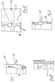
- FIGS 1 to 3 show a screw cap 10
- Plastic material with an internal thread 11 intended for this is a container mouth with a complementary external thread to close.
- Such screw caps are particularly for closing bottles with soft drinks or the like used, which is usually Reusable glass bottles with a standardized bottle mouth acts.
- the screw cap 10 includes a guarantee band 12.
- the first peripheral portion 14 connected to the cap so as to be tear-proof the guarantee band 12 is the same in the circumferential direction a first one that can be torn open when the cap is unscrewed for the first time
- This predetermined breaking point 17th 1 runs very well to the vertical 18 aslant. Specifically, this is the first predetermined breaking point by one Incision defined by a lower margin Tear-off web 19 and an upper one, located near the lower edge of the Cap extending tear-off web 20 is bridged.
- the Wall thickness of these tear-off webs 19 and 20 is in relation to Wall thickness of the guarantee tape, by the way, significantly lower.
- the predetermined breaking point defining incision is limited by an almost vertically extending section line 21 at the second, - of the cap tearable complementary section 15 of the guarantee tape 12 and a cutting line 22 running obliquely to the vertical 18 first circumferential section 14 connected to the cap so as to be tear-proof of the guarantee band 12.
- the directly to the so defined Predetermined breaking point 17 adjacent area 23 of the first, with the Cap tear-proof peripheral portion 14 of the Guarantee band 12 is additionally reinforced.
- This area has a larger wall thickness in comparison, in particular a wall thickness corresponding to the cap wall thickness. this applies especially for the transition area between them Area of the guarantee band and the lower edge 13 of the Screw cap 10. So it should be ensured that this Area 23 of the guarantee tape firmly with the lower edge 13 of the Screw cap 10 is connected and also remains connected before especially when you first unscrew the cap 10.
- Section line 22 extends at an angle ⁇ relative to Vertical 18, which corresponds to the angle at which the The predetermined breaking point 17 is the second one that can be torn off the cap Complementary section 15 of the guarantee tape 12 when torn off first circumferential section 14 connected to the cap so as to be tear-proof of the guarantee band 12 relative to the horizontal or
- connection between the complementary section 15 and the tear-resistant with the Screw cap connected peripheral portion 14 of the guarantee tape 12 remains initially with the consequence that when first Unscrew the screw cap from the lower edge 13 of the same separated complementary section 15 of the guarantee band 12 after tilts down, around a kind of hinge defining predetermined breaking point 17.
- the complementary section 15 The guarantee band 12 closes a sharp in this position Angle with the lower edge 13 of the screw cap 10. At the Demolition of the complementary section 15 from that with the Screw cap 10 fixedly connected first peripheral portion 14 of the Guarantee tape 12 corresponds to this angle approximately the angle ⁇ the section line 22, the effective course of the Predetermined breaking point 17 defined relative to the vertical 18.
- the tear-off webs 19, 20 of the predetermined breaking point 17 approximately perpendicular to the cutting line 22 or perpendicular to the oblique Course of the predetermined breaking point 17. This ensures that the tear of the guarantee tape in the circumferential direction of the same the predetermined breaking point 17 over the entire width of the Guarantee band is made uniformly. It will ensured that both the upper tear-off web 20 and the break lower tear-off bar 19; because, for example, only that would lower tear-off bar 19 near the edge when unscrewing the first time Tear off the cap, it would be conceivable that the retaining rib 16 overcomes the complementary ring bead at the container opening, without the upper tear-off web 20 tearing.
- the mentioned angle ⁇ between the vertical 18 and the Section line 22, which is the oblique course of the predetermined breaking point 17th defined is about 5 to 20 degrees, especially about 10 to 15 degrees, specifically 10 degrees here.
- the predetermined breaking point 12 can also be cut through an appropriately trained notch or material weakening be defined, which extends over the entire width of the Guarantee band 12 extends. At least one boundary line this notch or material weakening then extends in the Angle ⁇ , d. H. at an angle to the vertical 18.
- the tear-resistant connection between the first peripheral section 14 of the guarantee band 12 takes place in the illustrated Embodiment by a directly to the predetermined breaking point 17 adjacent over a predetermined angle of at least 15 degrees, here about 40 degrees continuously with the lower one Cap edge 13 connected connecting portion 24,
- the above already mentioned reinforcement area 23 includes, at least one, here three approximately diametrically to the connecting section 24 trained connecting webs 25 with one of the cap wall thickness corresponding wall thickness and a predetermined extent circumferentially over at least 5 to 10 degrees, and by several circumferentially formed between them Connecting webs 26 spaced uniformly from one another reduced wall thickness.
- the first, tearproof with the cap 10 connected peripheral portion 14 of the guarantee tape 12 extends in the illustrated embodiment over an angle of more than 180 degrees, especially about 210 degrees.
- This first one Circumferential portion 14 is from the second, tearable from the cap Complementary section 15 of the guarantee band 12 by a second, the first predetermined breaking point 17 approximately opposite arranged predetermined breaking point 27 separately.
- This second The predetermined breaking point is somewhat more tear-resistant in the circumferential direction designed as the first predetermined breaking point 17; the second Breakage point 27 is intended for the consumer after the first time Unscrew the screw cap 10 the complete removal of the Complementary section 15 of the screw cap 10 and the first, firmly connected to the screw cap 10 Lighten circumferential section 14 of the guarantee band 12.
- the second predetermined breaking point 27 is also through an incision defined (see Fig. 6), the edge of a tearable web 28 is bridged.
- the web 28 is formed on the inside in the form of a groove, in order to achieve this To tear off the complementary section 15 easier.
- the the second predetermined breaking point 27 extending incision preferably across the entire width of the guarantee band. In the embodiment according to FIG. 6, the mentioned incision starting from the bottom of the Guarantee band 12 only about 3/4 of the width of the Guarantee band 12.
- the connection between the guarantee band 12 and the lower edge 13 of the screw cap 10 in the area of second predetermined breaking point 27 is then preferably so trained as the connection of the tear-off webs between the Complementary section 15 of the guarantee band 12 and the lower Edge 13 of the screw cap 10.
- the tear-off webs mentioned between the lower edge 13 of the screw cap 10 and the Complementary section 15 of the guarantee band 12 are with the Reference numbers 29 marked.
- the angle between this section line 21 and the Vertical 18 is preferably slightly less than the angle ⁇ between the vertical 18 and the second cutting line 22, the to the tear-resistant peripheral portion 14 of the guarantee band 12 connects to the one desired above Get effect.
- the one that defines the predetermined breaking point 17 Incision tapers starting from this embodiment conical upwards from the lower edge of the guarantee band 12, especially asymmetrical conical.
- the arc line 30 is part of a parabola. Specifically, it sets in an angle of approximately 90 ° at the lower edge of the screw cap 10 or at the top of the guarantee band 12.
- the lower one lower tear-off web 19 is the end of the curved line 30 rounded and goes in the first, tear-resistant with the cap associated peripheral portion 14 of the guarantee band 12 associated lateral boundary (oblique section line 22) of the Predetermined breaking point 17 over.
- the above-described embodiment guarantees a when opening the screw cap 10 one Force transmission into the predetermined breaking point 17, in particular in the lower tear-off web 19 of the same, according to arrows 31, 32, i.e.
- the predetermined breaking line or tear line in the lower tear-off web 19 is usually the continuation of oblique cutting line 22, i.e. the one connected to the tearproof Section 14 of the guarantee band 12 associated lateral Limitation of the predetermined breaking point 17.
Landscapes
- Engineering & Computer Science (AREA)
- Mechanical Engineering (AREA)
- Closures For Containers (AREA)
- Golf Clubs (AREA)
Claims (17)
- Bouchon fileté (10) en matière plastique pour la fermeture d'une ouverture de récipient avec une bande de garantie (12) périphérique, disposée sur le bord inférieur (13) du bouchon et réalisée d'une seule pièce avec ce dernier,caractérisé en ce que l'angle (α), sous lequel s'étend le point destiné à la rupture (17) par rapport à la verticale (18), correspond à l'angle sous lequel s'étend par rapport à l'horizontale et/ou au sens périphérique sur le point destiné à la rupture (17) la seconde section complémentaire (15) de la bande de garantie (12), pouvant être déchirée du bouchon, lors de sa rupture de la première section périphérique (14) de la bande de garantie (12), assemblée de façon résistante à la déchirure avec le bouchon.qui est destinée, une fois le bouchon (10) mis en place, à enserrer un bourrelet annulaire sur l'ouverture du récipient, un moyen de retenue (16), prévu à cet effet sur le côté interne, pouvant être poussé sur le bourrelet lors de la première pose, en particulier lors du vissage du bouchon, et s'enclenchant sous le bourrelet dans la position finale du bouchon, etqui est subdivisée en une première section périphérique (14), assemblée de façon résistante à la déchirure avec le bouchon, ainsi qu'en une seconde section complémentaire (15), qui peut être déchirée du bouchon, la première section périphérique (14) de la bande de garantie (12), assemblée de façon résistante à la déchirure avec le bouchon, étant assemblée dans le sens périphérique de cette bande, par l'intermédiaire d'au moins un point destiné à la rupture (17) pouvant être déchiré lors du premier dévissage du bouchon, avec la seconde section complémentaire (15) pouvant être déchirée du bouchon, le point destiné à la rupture (17) se situant en oblique par rapport à la verticale (18),
- Bouchon fileté suivant la revendication 1, caractérisé en ce que l'angle (α), sous lequel s'étend le point destiné à la rupture (17) par rapport à la verticale (18), est à peu près de 5 à 20°, en particulier à peu près de 10 à 15°.
- Bouchon fileté suivant l'une des revendications 1 et 2, caractérisé en ce que le point destiné à la rupture (17) comporte au moins un profil (19) pouvant être déchiré dans le sens périphérique.
- Bouchon fileté suivant l'une des revendications 1 à 3, caractérisé en ce que le point destiné à la rupture (17) est défini par une entaille, pontée par au moins un profil de rupture (19) inférieur, proche du bord.
- Bouchon fileté suivant la revendication 4, caractérisé en ce que l'entaille est pontée par un autre profil de rupture supérieur (20), s'étendant à proximité du bord inférieur (13) du bouchon (10).
- Bouchon fileté suivant l'une des revendications 4 et 5, caractérisé en ce que l'entaille, définissant le point destiné à la rupture (17), est délimitée par une ligne de coupe (21) à peu près verticale sur la seconde section complémentaire (15) de la bande de garantie (12), pouvant être déchirée du bouchon, et par une ligne de coupe (22) s'étendant en oblique par rapport à la verticale (18) sur la première section périphérique (14) de la bande de garantie (12), assemblée de façon résistante à la déchirure avec le bouchon.
- Bouchon fileté suivant l'une des revendications 1 à 6, caractérisé en ce que la zone (23), directement limitrophe au point destiné à la rupture (17), de la première section périphérique (14) de la bande de garantie (12), assemblée de façon résistante à la déchirure avec le bouchon, est renforcée en supplément, présente en particulier une épaisseur de paroi comparativement plus élevée, de préférence une épaisseur de paroi correspondante à l'épaisseur de paroi du bouchon.
- Bouchon fileté suivant l'une des revendications 1 à 7, caractérisé en ce que seule la seconde section complémentaire (15) de la bande de garantie (12), pouvant être déchirée du bouchon (10), présente des moyens de retenue en forme de plusieurs éléments de retenue individuels répartis discrètement sur le pourtour, ou en forme d'une nervure de retenue (16) continue.
- Bouchon fileté suivant l'une des revendications 1 à 8, caractérisé en ce que l'assemblage résistant à la déchirure entre la première section périphérique (14) de la bande de garantie (12) et le bouchon (10) est assuré parune section d'assemblage (24) directement limitrophe au point destiné à la rupture (17), assemblée en continu sur un angle prédéfini (β) d'au moins 15° avec le bord inférieur (13) du bouchon,au moins un profil d'assemblage (25), réalisé à peu près diamétralement par rapport à cette section et d'une épaisseur de paroi correspondante à l'épaisseur de paroi du bouchon, et parplusieurs profils d'assemblage (26) intermédiaires d'une épaisseur de paroi inférieure, distants les uns des autres dans le sens périphérique.
- Bouchon fileté suivant l'une des revendications 1 à 9, caractérisé en ce que la première section périphérique (14) de la bande de garantie (12), assemblée de façon résistante à la déchirure avec le bouchon (10), s'étend sur un angle de plus de 180°, en particulier d'à peu près 190 à 210°, et en ce que cette première section périphérique (14) est séparée de la seconde section complémentaire (15) de la bande de garantie (12), pouvant être déchirée du bouchon, par un second point destiné à la rupture (27) disposé à peu près en vis-à-vis du premier point destiné à la rupture (17).
- Bouchon fileté suivant la revendication 10, caractérisé en ce que le second point destiné à la rupture (27) est défini par une entaille, pontée au moins côté bord par un profil (28) pouvant être déchiré.
- Bouchon fileté suivant la revendication 11, caractérisé en ce que l'entaille, définissant le second point destiné à la rupture (27), ne s'étend à partir du bord inférieur de la bande de garantie (12) que sur à peu près la moitié de la largeur, ou 3/4 de la largeur de la bande de garantie (12).
- Bouchon fileté suivant l'une des revendications 1 à 12, caractérisé en ce que l'assemblage entre le bord inférieur (13) du bouchon (10) et la seconde section complémentaire (15) de la bande de garantie (12), pouvant être déchirée du bouchon, est assuré par au moins deux, en particulier 4 à 6 profils de rupture (29) disposés à distance les uns des autres, dont l'épaisseur de paroi est inférieure à l'épaisseur de paroi du bouchon ou de la bande de garantie.
- Bouchon fileté suivant l'une ou plusieurs des revendications 7 à 13, caractérisé en ce que la zone (23), directement limitrophe au point destiné à la rupture (17) et renforcée en supplément, de la première section périphérique (14) de la bande de garantie (12), assemblée de façon résistante à la déchirure avec le bouchon, est limitée sur le côté opposé au point destiné à la rupture (17) par une ligne courbe (30) s'étendant en direction du profil de rupture inférieur (19) proche du bord, et/ou est délimitée par rapport à la partie restante de la première section périphérique (14).
- Bouchon fileté suivant la revendication 14, caractérisé en ce que la ligne courbe (30) fait partie d'une parabole.
- Bouchon fileté suivant l'une des revendications 14 et 15, caractérisé en ce que la ligne courbe (30) s'engage sous un angle d'à peu près 90° sur le bord inférieur du bouchon fileté (10) et/ou sur le bord supérieur de la bande de garantie (12).
- Bouchon fileté suivant l'une des revendications 14 à 16, caractérisé en ce que l'extrémité inférieure de la ligne courbe (30), tournée vers le profil de rupture inférieur (19), est arrondie, et se prolonge par la limitation latérale (ligne de coupe oblique 22) du point destiné à la rupture (17), associée à la première section périphérique (14) de la bande de garantie (12), assemblée de façon résistante à la déchirure avec le bouchon.
Applications Claiming Priority (2)
| Application Number | Priority Date | Filing Date | Title |
|---|---|---|---|
| DE19730324A DE19730324A1 (de) | 1997-07-15 | 1997-07-15 | Schraubkappe mit Garantieband |
| DE19730324 | 1997-07-15 |
Publications (3)
| Publication Number | Publication Date |
|---|---|
| EP0891929A2 EP0891929A2 (fr) | 1999-01-20 |
| EP0891929A3 EP0891929A3 (fr) | 1999-02-03 |
| EP0891929B1 true EP0891929B1 (fr) | 2001-11-07 |
Family
ID=7835785
Family Applications (1)
| Application Number | Title | Priority Date | Filing Date |
|---|---|---|---|
| EP98108918A Expired - Lifetime EP0891929B1 (fr) | 1997-07-15 | 1998-05-15 | Capuchon à vis avec bande de garantie |
Country Status (3)
| Country | Link |
|---|---|
| EP (1) | EP0891929B1 (fr) |
| AT (1) | ATE208329T1 (fr) |
| DE (2) | DE19730324A1 (fr) |
Families Citing this family (1)
| Publication number | Priority date | Publication date | Assignee | Title |
|---|---|---|---|---|
| EP1151932A1 (fr) * | 2000-05-03 | 2001-11-07 | Mouldtec Kunststoff GmbH | Fermeture en matière plastique, en particulier capuchon fileté, avec bande de garantie |
Family Cites Families (6)
| Publication number | Priority date | Publication date | Assignee | Title |
|---|---|---|---|---|
| DE2439414A1 (de) * | 1974-08-16 | 1976-03-04 | Hohenzollern Huettenverwalt | Kunststoffverschluss fuer flaschen und behaelter |
| US4278180A (en) * | 1980-01-24 | 1981-07-14 | Aluminum Company Of America | Container closure with breakable annular ring |
| ATE96110T1 (de) * | 1988-11-28 | 1993-11-15 | Crown Cork Ag | Schraubkappe mit garantieband. |
| NO911503L (no) * | 1990-04-27 | 1991-10-28 | Crown Cork Ag | Skrukappe med et garantibaand som er utvidbart ved foerstegangs oppskruing. |
| FR2710325B1 (fr) * | 1993-09-22 | 1995-12-08 | Jacques Perchepied | Bouchon à visser. |
| IT1271496B (it) * | 1993-11-29 | 1997-05-30 | Bruno Taddei | Tappo a vite in resina sintetica stampata,con sigillo di garanzia |
-
1997
- 1997-07-15 DE DE19730324A patent/DE19730324A1/de active Pending
-
1998
- 1998-05-15 AT AT98108918T patent/ATE208329T1/de active
- 1998-05-15 DE DE59802030T patent/DE59802030D1/de not_active Expired - Lifetime
- 1998-05-15 EP EP98108918A patent/EP0891929B1/fr not_active Expired - Lifetime
Also Published As
| Publication number | Publication date |
|---|---|
| EP0891929A3 (fr) | 1999-02-03 |
| EP0891929A2 (fr) | 1999-01-20 |
| ATE208329T1 (de) | 2001-11-15 |
| DE19730324A1 (de) | 1999-01-28 |
| DE59802030D1 (de) | 2001-12-13 |
Similar Documents
| Publication | Publication Date | Title |
|---|---|---|
| EP3995410B1 (fr) | Combinaison d'un col de récipient et d'une fermeture imperdable à angle d'ouverture stabilisé | |
| DE69630596T2 (de) | Originalitätsverschluss mit garantieband | |
| EP0254673B1 (fr) | Couvercle de récipient muni d'une bague de garantie | |
| EP1429973B1 (fr) | Bouchon a vis | |
| EP0364775B1 (fr) | Fermeture à vis | |
| EP1092640A1 (fr) | Fermeture inviolable | |
| EP0154603A1 (fr) | Capsule de bouchage en matière plastique | |
| DE202020100758U1 (de) | Unverlierbarer Verschluss mit stabilisiertem Öffnungswinkel | |
| WO2021018772A1 (fr) | Bouchon captif ayant un angle d'ouverture stabilisé | |
| EP0371920B1 (fr) | Fermeture à vis avec bande de garantie | |
| EP0281514A1 (fr) | Capsule de fermeture à bande de garantie | |
| EP0451102A1 (fr) | Capsule en matière plastique | |
| DE3833945C1 (en) | Plastic securing ring for a screw closure for containers | |
| DE3727887C2 (fr) | ||
| WO1992013773A1 (fr) | Capsule de bouteille a anneau garantissant la fermeture d'origine | |
| EP0891929B1 (fr) | Capuchon à vis avec bande de garantie | |
| EP0886606B1 (fr) | Orifice de contenant et bouchon de fermeture | |
| DE4015510A1 (de) | Verschlusskappe fuer infusions- oder transfusionsflaschen | |
| EP1029798A1 (fr) | Capuchon de fermeture | |
| EP1529005B1 (fr) | Dispositif de fermeture/deversement combine comprenant une securite d'authenticite | |
| DE2439414A1 (de) | Kunststoffverschluss fuer flaschen und behaelter | |
| EP0564999B1 (fr) | Capsule de bouteille à anneau garantissant la fermeture d'origine | |
| EP0965533A1 (fr) | Bouchon de fermeture, en particulier bouchon fileté en plastique avec une bande de garantie | |
| DE3227510C2 (fr) | ||
| DE29606358U1 (de) | Flaschenverschluß aus Kunststoff |
Legal Events
| Date | Code | Title | Description |
|---|---|---|---|
| PUAI | Public reference made under article 153(3) epc to a published international application that has entered the european phase |
Free format text: ORIGINAL CODE: 0009012 |
|
| PUAL | Search report despatched |
Free format text: ORIGINAL CODE: 0009013 |
|
| AK | Designated contracting states |
Kind code of ref document: A2 Designated state(s): AT CH DE LI |
|
| AX | Request for extension of the european patent |
Free format text: AL;LT;LV;MK;RO;SI |
|
| AK | Designated contracting states |
Kind code of ref document: A3 Designated state(s): AT BE CH CY DE DK ES FI FR GB GR IE IT LI LU MC NL PT SE |
|
| AX | Request for extension of the european patent |
Free format text: AL;LT;LV;MK;RO;SI |
|
| 17P | Request for examination filed |
Effective date: 19990128 |
|
| AKX | Designation fees paid |
Free format text: AT CH DE LI |
|
| 17Q | First examination report despatched |
Effective date: 20000201 |
|
| GRAG | Despatch of communication of intention to grant |
Free format text: ORIGINAL CODE: EPIDOS AGRA |
|
| GRAG | Despatch of communication of intention to grant |
Free format text: ORIGINAL CODE: EPIDOS AGRA |
|
| GRAH | Despatch of communication of intention to grant a patent |
Free format text: ORIGINAL CODE: EPIDOS IGRA |
|
| GRAH | Despatch of communication of intention to grant a patent |
Free format text: ORIGINAL CODE: EPIDOS IGRA |
|
| GRAA | (expected) grant |
Free format text: ORIGINAL CODE: 0009210 |
|
| AK | Designated contracting states |
Kind code of ref document: B1 Designated state(s): AT CH DE LI |
|
| REF | Corresponds to: |
Ref document number: 208329 Country of ref document: AT Date of ref document: 20011115 Kind code of ref document: T |
|
| REG | Reference to a national code |
Ref country code: CH Ref legal event code: EP |
|
| REG | Reference to a national code |
Ref country code: CH Ref legal event code: NV Representative=s name: TROESCH SCHEIDEGGER WERNER AG |
|
| REF | Corresponds to: |
Ref document number: 59802030 Country of ref document: DE Date of ref document: 20011213 |
|
| PLBE | No opposition filed within time limit |
Free format text: ORIGINAL CODE: 0009261 |
|
| STAA | Information on the status of an ep patent application or granted ep patent |
Free format text: STATUS: NO OPPOSITION FILED WITHIN TIME LIMIT |
|
| 26N | No opposition filed | ||
| PGFP | Annual fee paid to national office [announced via postgrant information from national office to epo] |
Ref country code: AT Payment date: 20120525 Year of fee payment: 15 |
|
| PGFP | Annual fee paid to national office [announced via postgrant information from national office to epo] |
Ref country code: CH Payment date: 20130524 Year of fee payment: 16 |
|
| PGFP | Annual fee paid to national office [announced via postgrant information from national office to epo] |
Ref country code: DE Payment date: 20130730 Year of fee payment: 16 |
|
| REG | Reference to a national code |
Ref country code: DE Ref legal event code: R119 Ref document number: 59802030 Country of ref document: DE |
|
| REG | Reference to a national code |
Ref country code: CH Ref legal event code: PL |
|
| REG | Reference to a national code |
Ref country code: AT Ref legal event code: MM01 Ref document number: 208329 Country of ref document: AT Kind code of ref document: T Effective date: 20140515 |
|
| PG25 | Lapsed in a contracting state [announced via postgrant information from national office to epo] |
Ref country code: CH Free format text: LAPSE BECAUSE OF NON-PAYMENT OF DUE FEES Effective date: 20140531 Ref country code: LI Free format text: LAPSE BECAUSE OF NON-PAYMENT OF DUE FEES Effective date: 20140531 |
|
| PG25 | Lapsed in a contracting state [announced via postgrant information from national office to epo] |
Ref country code: AT Free format text: LAPSE BECAUSE OF NON-PAYMENT OF DUE FEES Effective date: 20140515 |
|
| REG | Reference to a national code |
Ref country code: DE Ref legal event code: R119 Ref document number: 59802030 Country of ref document: DE Effective date: 20141202 |
|
| PG25 | Lapsed in a contracting state [announced via postgrant information from national office to epo] |
Ref country code: DE Free format text: LAPSE BECAUSE OF NON-PAYMENT OF DUE FEES Effective date: 20141202 |