EP0891938A2 - Machine et procédé pour empiler - Google Patents
Machine et procédé pour empiler Download PDFInfo
- Publication number
- EP0891938A2 EP0891938A2 EP98305670A EP98305670A EP0891938A2 EP 0891938 A2 EP0891938 A2 EP 0891938A2 EP 98305670 A EP98305670 A EP 98305670A EP 98305670 A EP98305670 A EP 98305670A EP 0891938 A2 EP0891938 A2 EP 0891938A2
- Authority
- EP
- European Patent Office
- Prior art keywords
- conveyor belt
- bundles
- stacking
- article
- stacking station
- Prior art date
- Legal status (The legal status is an assumption and is not a legal conclusion. Google has not performed a legal analysis and makes no representation as to the accuracy of the status listed.)
- Granted
Links
Images


Classifications
-
- B—PERFORMING OPERATIONS; TRANSPORTING
- B65—CONVEYING; PACKING; STORING; HANDLING THIN OR FILAMENTARY MATERIAL
- B65H—HANDLING THIN OR FILAMENTARY MATERIAL, e.g. SHEETS, WEBS, CABLES
- B65H33/00—Forming counted batches in delivery pile or stream of articles
- B65H33/14—Forming counted batches in delivery pile or stream of articles by diverting batches to separate receivers
-
- B—PERFORMING OPERATIONS; TRANSPORTING
- B65—CONVEYING; PACKING; STORING; HANDLING THIN OR FILAMENTARY MATERIAL
- B65H—HANDLING THIN OR FILAMENTARY MATERIAL, e.g. SHEETS, WEBS, CABLES
- B65H29/00—Delivering or advancing articles from machines; Advancing articles to or into piles
- B65H29/12—Delivering or advancing articles from machines; Advancing articles to or into piles by means of the nip between two, or between two sets of, moving tapes or bands or rollers
- B65H29/14—Delivering or advancing articles from machines; Advancing articles to or into piles by means of the nip between two, or between two sets of, moving tapes or bands or rollers and introducing into a pile
-
- B—PERFORMING OPERATIONS; TRANSPORTING
- B65—CONVEYING; PACKING; STORING; HANDLING THIN OR FILAMENTARY MATERIAL
- B65H—HANDLING THIN OR FILAMENTARY MATERIAL, e.g. SHEETS, WEBS, CABLES
- B65H31/00—Pile receivers
- B65H31/24—Pile receivers multiple or compartmented, e.d. for alternate, programmed, or selective filling
-
- B—PERFORMING OPERATIONS; TRANSPORTING
- B65—CONVEYING; PACKING; STORING; HANDLING THIN OR FILAMENTARY MATERIAL
- B65H—HANDLING THIN OR FILAMENTARY MATERIAL, e.g. SHEETS, WEBS, CABLES
- B65H31/00—Pile receivers
- B65H31/30—Arrangements for removing completed piles
- B65H31/3081—Arrangements for removing completed piles by acting on edge of the pile for moving it along a surface, e.g. by pushing
-
- B—PERFORMING OPERATIONS; TRANSPORTING
- B65—CONVEYING; PACKING; STORING; HANDLING THIN OR FILAMENTARY MATERIAL
- B65H—HANDLING THIN OR FILAMENTARY MATERIAL, e.g. SHEETS, WEBS, CABLES
- B65H31/00—Pile receivers
- B65H31/34—Apparatus for squaring-up piled articles
- B65H31/38—Apparatus for vibrating or knocking the pile during piling
-
- B—PERFORMING OPERATIONS; TRANSPORTING
- B65—CONVEYING; PACKING; STORING; HANDLING THIN OR FILAMENTARY MATERIAL
- B65H—HANDLING THIN OR FILAMENTARY MATERIAL, e.g. SHEETS, WEBS, CABLES
- B65H2301/00—Handling processes for sheets or webs
- B65H2301/40—Type of handling process
- B65H2301/44—Moving, forwarding, guiding material
- B65H2301/443—Moving, forwarding, guiding material by acting on surface of handled material
- B65H2301/4431—Moving, forwarding, guiding material by acting on surface of handled material by means with operating surfaces contacting opposite faces of material
-
- B—PERFORMING OPERATIONS; TRANSPORTING
- B65—CONVEYING; PACKING; STORING; HANDLING THIN OR FILAMENTARY MATERIAL
- B65H—HANDLING THIN OR FILAMENTARY MATERIAL, e.g. SHEETS, WEBS, CABLES
- B65H2404/00—Parts for transporting or guiding the handled material
- B65H2404/20—Belts
- B65H2404/23—Belts with auxiliary handling means
- B65H2404/231—Belts with auxiliary handling means pocket or gripper type
-
- B—PERFORMING OPERATIONS; TRANSPORTING
- B65—CONVEYING; PACKING; STORING; HANDLING THIN OR FILAMENTARY MATERIAL
- B65H—HANDLING THIN OR FILAMENTARY MATERIAL, e.g. SHEETS, WEBS, CABLES
- B65H2404/00—Parts for transporting or guiding the handled material
- B65H2404/20—Belts
- B65H2404/23—Belts with auxiliary handling means
- B65H2404/232—Blade, plate, finger
-
- B—PERFORMING OPERATIONS; TRANSPORTING
- B65—CONVEYING; PACKING; STORING; HANDLING THIN OR FILAMENTARY MATERIAL
- B65H—HANDLING THIN OR FILAMENTARY MATERIAL, e.g. SHEETS, WEBS, CABLES
- B65H2701/00—Handled material; Storage means
- B65H2701/10—Handled articles or webs
- B65H2701/19—Specific article or web
- B65H2701/1924—Napkins or tissues, e.g. dressings, toweling, serviettes, kitchen paper and compresses
-
- Y—GENERAL TAGGING OF NEW TECHNOLOGICAL DEVELOPMENTS; GENERAL TAGGING OF CROSS-SECTIONAL TECHNOLOGIES SPANNING OVER SEVERAL SECTIONS OF THE IPC; TECHNICAL SUBJECTS COVERED BY FORMER USPC CROSS-REFERENCE ART COLLECTIONS [XRACs] AND DIGESTS
- Y10—TECHNICAL SUBJECTS COVERED BY FORMER USPC
- Y10T—TECHNICAL SUBJECTS COVERED BY FORMER US CLASSIFICATION
- Y10T83/00—Cutting
- Y10T83/04—Processes
- Y10T83/0476—Including stacking of plural workpieces
-
- Y—GENERAL TAGGING OF NEW TECHNOLOGICAL DEVELOPMENTS; GENERAL TAGGING OF CROSS-SECTIONAL TECHNOLOGIES SPANNING OVER SEVERAL SECTIONS OF THE IPC; TECHNICAL SUBJECTS COVERED BY FORMER USPC CROSS-REFERENCE ART COLLECTIONS [XRACs] AND DIGESTS
- Y10—TECHNICAL SUBJECTS COVERED BY FORMER USPC
- Y10T—TECHNICAL SUBJECTS COVERED BY FORMER US CLASSIFICATION
- Y10T83/00—Cutting
- Y10T83/202—With product handling means
- Y10T83/2033—Including means to form or hold pile of product pieces
-
- Y—GENERAL TAGGING OF NEW TECHNOLOGICAL DEVELOPMENTS; GENERAL TAGGING OF CROSS-SECTIONAL TECHNOLOGIES SPANNING OVER SEVERAL SECTIONS OF THE IPC; TECHNICAL SUBJECTS COVERED BY FORMER USPC CROSS-REFERENCE ART COLLECTIONS [XRACs] AND DIGESTS
- Y10—TECHNICAL SUBJECTS COVERED BY FORMER USPC
- Y10T—TECHNICAL SUBJECTS COVERED BY FORMER US CLASSIFICATION
- Y10T83/00—Cutting
- Y10T83/202—With product handling means
- Y10T83/2033—Including means to form or hold pile of product pieces
- Y10T83/2037—In stacked or packed relation
-
- Y—GENERAL TAGGING OF NEW TECHNOLOGICAL DEVELOPMENTS; GENERAL TAGGING OF CROSS-SECTIONAL TECHNOLOGIES SPANNING OVER SEVERAL SECTIONS OF THE IPC; TECHNICAL SUBJECTS COVERED BY FORMER USPC CROSS-REFERENCE ART COLLECTIONS [XRACs] AND DIGESTS
- Y10—TECHNICAL SUBJECTS COVERED BY FORMER USPC
- Y10T—TECHNICAL SUBJECTS COVERED BY FORMER US CLASSIFICATION
- Y10T83/00—Cutting
- Y10T83/202—With product handling means
- Y10T83/2033—Including means to form or hold pile of product pieces
- Y10T83/2037—In stacked or packed relation
- Y10T83/204—Stacker sweeps along product support
-
- Y—GENERAL TAGGING OF NEW TECHNOLOGICAL DEVELOPMENTS; GENERAL TAGGING OF CROSS-SECTIONAL TECHNOLOGIES SPANNING OVER SEVERAL SECTIONS OF THE IPC; TECHNICAL SUBJECTS COVERED BY FORMER USPC CROSS-REFERENCE ART COLLECTIONS [XRACs] AND DIGESTS
- Y10—TECHNICAL SUBJECTS COVERED BY FORMER USPC
- Y10T—TECHNICAL SUBJECTS COVERED BY FORMER US CLASSIFICATION
- Y10T83/00—Cutting
- Y10T83/202—With product handling means
- Y10T83/2033—Including means to form or hold pile of product pieces
- Y10T83/2037—In stacked or packed relation
- Y10T83/2057—Including means to deliver individual pieces to a stack holder
-
- Y—GENERAL TAGGING OF NEW TECHNOLOGICAL DEVELOPMENTS; GENERAL TAGGING OF CROSS-SECTIONAL TECHNOLOGIES SPANNING OVER SEVERAL SECTIONS OF THE IPC; TECHNICAL SUBJECTS COVERED BY FORMER USPC CROSS-REFERENCE ART COLLECTIONS [XRACs] AND DIGESTS
- Y10—TECHNICAL SUBJECTS COVERED BY FORMER USPC
- Y10T—TECHNICAL SUBJECTS COVERED BY FORMER US CLASSIFICATION
- Y10T83/00—Cutting
- Y10T83/202—With product handling means
- Y10T83/2092—Means to move, guide, or permit free fall or flight of product
- Y10T83/2183—Product mover including gripper means
-
- Y—GENERAL TAGGING OF NEW TECHNOLOGICAL DEVELOPMENTS; GENERAL TAGGING OF CROSS-SECTIONAL TECHNOLOGIES SPANNING OVER SEVERAL SECTIONS OF THE IPC; TECHNICAL SUBJECTS COVERED BY FORMER USPC CROSS-REFERENCE ART COLLECTIONS [XRACs] AND DIGESTS
- Y10—TECHNICAL SUBJECTS COVERED BY FORMER USPC
- Y10T—TECHNICAL SUBJECTS COVERED BY FORMER US CLASSIFICATION
- Y10T83/00—Cutting
- Y10T83/202—With product handling means
- Y10T83/2092—Means to move, guide, or permit free fall or flight of product
- Y10T83/2192—Endless conveyor
-
- Y—GENERAL TAGGING OF NEW TECHNOLOGICAL DEVELOPMENTS; GENERAL TAGGING OF CROSS-SECTIONAL TECHNOLOGIES SPANNING OVER SEVERAL SECTIONS OF THE IPC; TECHNICAL SUBJECTS COVERED BY FORMER USPC CROSS-REFERENCE ART COLLECTIONS [XRACs] AND DIGESTS
- Y10—TECHNICAL SUBJECTS COVERED BY FORMER USPC
- Y10T—TECHNICAL SUBJECTS COVERED BY FORMER US CLASSIFICATION
- Y10T83/00—Cutting
- Y10T83/202—With product handling means
- Y10T83/2092—Means to move, guide, or permit free fall or flight of product
- Y10T83/2192—Endless conveyor
- Y10T83/2194—And means to remove product therefrom
Definitions
- the invention relates to machines for cutting, conveying and stacking web material and related methods.
- this stacking machine is unsuitable for stacking bundles severed from multiply ropes formed of folded dry web material where the plies are not wetted and the top ply is not cohesively bonded to the lower plies and is susceptible to being blown up and then bent out of proper position on the bundle.
- the invention is an improved article stacking machine and method for continuously stacking articles, typically folded sheets or stacks of folded sheets, supplied to the machine.
- a cutter cuts a continuous rope to form the articles.
- the machine and method are particularly useful in high production rate continuous stacking of bundles severed from the lead end of an indefinite length multiply dry rope fed to the machine.
- the rope typically includes four or five stacked plies of folded dry web material, such as fabric softener sheets or paper towel sheets.
- the plies may be folded as desired.
- a Z-fold is typical.
- Bundles are stacked without fold back of the sheet edges. While the machine is particularly adapted to rapid production stacking of dry bundles, it may also be used to stack bundles which have been wetted.
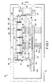
- Stacking machine 10 includes a rectangular frame 12 supporting a cutter, a pair of bundle cutoff rolls 14, a bundle conveyor 16 extending downstream from the rolls 14, a pair of like drop-type stations 18 and 20 spaced along conveyor 16 and a stack takeaway conveyor 22 located to one side of bundle conveyor 16.
- Cutoff rolls 14 are of the type disclosed in U.S. Patent No. 5,363,728, assigned to Elsner Engineering Works, Inc., the disclosure of which is incorporated herein by reference.
- the cutter includes a knife roll 24 having three radially extending and circumferentially spaced cutoff knives 26 and an anvil roll 28 located below the knife roll and cooperative with the knife roll. Both rolls 24 and 28 are rotated by appropriate drives in the directions of arrows 30 shown in Figure 2 to sever the lead end of a flat mutiply rope of folded web material.
- the rope is fed downstream in the direction of arrow 32 between the rolls, as shown in Fires 1 and 2.
- the end of the rope is cut into multiply segments or bundles which are discharged from the cutoff rolls and are fed downstream to the bundle conveyor 16 which moves the bundles to stacking stations 18 and 20.
- Conveyor 16 includes a pair of elongate horizontally extending vertical plates 34 and 36 extending in a downstream direction from rolls 14.
- Continuous flat conveyor belt 38 is wound around a pair of rollers 40 and 42.
- Roller 40 is located immediately downstream and slightly above the nip between cutoff rolls 14.
- a suitable drive rotates roller 40 in the direction of arrow 44 to move the lower run 46 of belt 38 in a downstream direction away from the cutoff rolls.
- Lower run 46 slides along a fixed elongate support plate 48 extending over and past stations 18 and 20.
- Endless toothed clamp conveyor belt 50 is wound around a pair of toothed rollers 52 and 54 as shown in Figures 1 and 2 and includes an ripper run 56 extending between the rollers.
- Belt 20 and rollers 52 and 54 are offset to one side of belt 38, as illustrated best in Figure 1.
- a plurality of clamp arms 58 are mounted on belt 50 and extend from belt 50 toward and under belt 38.
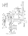
- Each clamp arm 58 includes an elongate base 60 extended transversely across the outer surface of belt 38 and an arm extension 62 which projects from the base toward and under belt 38, as illustrated in Figure 3.
- the extension 62 is connected to base 60 by horizontal hinge connection 64 to permit upward pivoting of the extension toward the lower run 46 of belt 38.
- Tension spring 66 extends between supports extending above the base 60 and extension 62 to bias the extension upwardly about the hinge connection. Upward pivotal movement of the arm extension is limited by adjustable stop 68 on the base which engages an abutment 70 on extension 62 adjacent the hinge. See Figure 5.
- Mounting plate 72 is secured to the side of base 60 away from spring 66 with belt 50 sandwiched between the plate and the base.
- the plate includes a rib which fits within a groove on the side of the belt away from the base to accurately hold the clamp arm on the belt in a desired longitudinal position on the belt and with the base extending perpendicularly to the belt.
- Clamp element 74 which may be formed of relatively low friction nylon, is mounted on the free end of extension 62 on a pivot pin 76 which permits pivoting of the element about an axis extending parallel to the axis of hinge 64 and along the length of lower belt run 46. Free pivoting of the clamp element about pin 76 insures that the element is held flush against a bundle clamped between the member and belt 38, independent of the thickness of the bundle.
- a suitable drive continuously moves the upper run 56 of belt 50 downstream between rollers 52 and 54 at the same speed that the lower run 46 of belt 38 moves downstream from roller 40 to roller 42.
- the mounting plates 60 extend beyond the edges of clamp belt 50, as indicated in Figure 3, and are seated in opposed recesses 78 formed in the flanges of rollers 52 and 54 as the clamp arms are moved around the rollers. Positive engagement between the clamp arms and rollers supports the arms as they are brought up and into engagement with the under sides of lead ends of severed bundles to clamp the bundles against lower run 46 of belt 38, as illustrated more clearly in Figures 8-10 and described more fully below.
- the drive for belt 50 rotates roller 52 in the direction of arrow 80.
- roller 40 is located immediately downstream from the nip between knife roll 24 and anvil roll 28, and is located above driven roller 86.
- Plate 88 extends from one nip downstream past roller 86 and under the upstream end of run 46.
- Stacking stations 18 and 20 are spaced along bundle conveyor 6 under belt 38.
- Station 20 is located further downstream from rolls 14 than station 18 and includes a slotted stack support plate 90 movably mounted on a pair of vertical support rods 92 permitting vertical movement of the plate between full lowered and elevated positions indicated in Figure 3.
- Plate 90 is raised and lowered by a suitable drive, as will be described below.
- the upstream and downstream ends of the stacking stations are defined by adjustable upstream vertical guide plate 94 and downstream vertical guide plate 96.
- Plate 96 is mounted on frame 10 by eccentric vibrators 98 which vibrate or jog plate 96 for even stacking of bundles on the support plate.
- Stack shift comb 100 is mounted on a pair of parallel horizontal rods 102 and includes a number of spaced fingers 104 which extend upwardly through slots formed in the stack support plate 90.
- the comb is moveable along rods 102 and is connected to piston rod 108 of hydraulic cylinder 110 which, in turn, is mounted on frame 12.
- Cylinder 110 moves the fingers 104 from a retracted position where the fingers are located at the bottoms of the slots in plate 90, as shown in solid line in Figure 3, to an extended position where the fingers have been moved out of the slots in plate 90 and into slcts formed in support plate 112 of takeaway conveyor 22.
- Threety degree slotted guide plate 114 extends along the outer side of station 20 between plates 94 and 96 to assist in maintaining the orientation of the bundles during stacking. Plate 114 is slotted to permit movement of the fingers between the extended and retracted positions.
- Bundle support plate 95 extends upstream from the top of plate 94 under conveyor run 46 and includes a right angle upstream-extending portion of plate 94. The plate 95 supports trailing portions of bundles moved downstream by conveyor 16. The upstream end of plate 94 is located above plate 96 of stacking station 18.
- Station 18 is like station 20 and need not be described further. Plate 95 of station 18 extends upstream to roller 52, as illustrated in Figure 2.
- a pair of fixed stop or release fingers 116 associated with station 20 are mounted on a cross bar 118 extending between plates 34 and 38 and extend down from the bar to either side of the support plate 48 and clamp arm clamp members 74.
- the fingers 116 are located above vibrated end plate 96 at the downstream side of the stacking station.
- a pair of retractable stop fingers 120 are associated with station 18 are mounted on rotatable shaft 122 journaled in. bearings in plates 34 and 36.
- An air cylinder 124 is mounted on a cross bar 126 extending between plates 34 and 36 and is connected to an end of radial arm 128 on shaft 122.
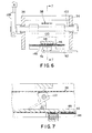
- Extension of cylinder 124 positions the stop fingers 120 to either side of the support plate 48, lower conveyor belt run 46 and clamp elements 74, as illustrated in Figure 6, where the ends of the stop fingers are in the path of downstream movement of the edges of product bundles clamped between elements 74 and lower conveyor run 46. See Figure 6.
- Retraction of cylinder 124 rotates and retracts the adjustable stop fingers 120 above the bottom of support plate 48, out of the path of downstream movement of the clamped bundles.
- Stack takeway conveyor 22 includes a pair of spaced apart sprocket gears 130, 132 and a drive chain 134 wound around the sears and having an upper run 136 located a short distance below plate 112.
- a plurality of spaced pusher fingers 138 are mounted at spaced intervals on chain 134.
- the fingers 138 on the upper run 136 extend upwardly through slot 140 in the plate and project above the plate to engage product stacks discharged from stacking stations 18 and 20 and onto plate 112 and move the stacks downstream to discharged belts 142 on takeaway conveyor extension 144.
- the stacking machine operates continuously to sever successive bundles of folded web material from the lead end of a multiply rope fed in the direction of arrow 32 to cutoff rolls 14.
- the rope is fed downstream through the cutoff rolls 14 and onto plate 88.
- the downstream end of the rope 150 is fed between downstream rotating rolls 40 and 86 before the rope is severed to form a bundle.
- Belt 38 and roll 86 move downstream at a speed faster than the feed speed of the rope and the belt and roll slip on the top and bottom of the lead end of the rope until the bundle is severed, then engage the new bundle and accelerate the bundle away from the nip of cutter rolls 14.
- the severed bundle is then fed downstream between roll 86 and the conveyor belt 38 wrapped around the roll 40 at a speed greater than the speed at which the rope is fed downstream, creating gap 148 between the end of the rope and the bundle.
- the downstream fed bundle, confined between the conveyor belt 38, and plate 88 is fed past the end of plate 88 as shown in Figure 8.
- a clamp arm 58 on belt 50 is rotated up around roller 52 and is raised up under belt run 46 and into contact with the downstream end of bundle 146 to positively clamp the lead end of the bundle against the downstream conveyor run 46, which, in turn, is supported by plate 48.
- Clamping occurs while the bundle is held between the belt and roller 86 and while the base of the clamp arm is positively supported in a notch 78 on roller 52 to increase the initial tact pressure between the clamp element 74 and the conveyor belt run 46.
- Positive clamping ensures that the bundle Is held on the belt and moves downstream with the belt. Clamping occurs without longitudinal or lateral relative movement between belt run 46, bundle 146 and the clamp element 74. Gap 148 widens until the next bundle is severed from the rope.
- the lead ends of the rope and of bundles cut from the cope are positively held on the conveyor at all times prior to release at a stacking station, to insure proper feeding and to prevent fold back of the edges of the dry webs in the bundle.
- Rolls 40 and 86 are spaced a distance downstream from the nip of cutoff rolls 14 less the length of the bundle to insure that the bundle is captured prior to severing from the rope.
- the position on conveyor 16 at which the lead end of the bundle is securely clamped against run 46 and plate 48 is located a distance downstream from rolls 40 and 86 less than the length of the bundle 146.
- the speed of conveyor 16 is greater than the speed at which rope 150 is fed to the cutoff rolls and insures a wide gap 148 between adjacent bundles so that bundles are dropped at stations 18 and 20 free of adjacent upstream bundles.
- Clamped bundles 146 are moved downstream along conveyor 16 and are stripped from between the clamp arms and belt 38 at either stacking station 18 and 20, depending upon the position of adjustable stop fingers 120. Stripping of a bundle from between a clamped element 74 and lower conveyor run 46 occurs when the sides of the lead end of the bundle are brought into contact with a pair of stop fingers 116, 120 which are extended into the path of movement of the bundle. See, for instance, Figure 6. The clamped, moving bundle contacts and is stopped by the fingers. The lower conveyor run 46, and clamp element 74 on the arm 58 continue to move downstream past the stripped bundle. Stop fingers 116 and 120 are located above the downstream end plates 96 of stacking stations 20 and 18, respectively, so that stripped bundles fall down into the stations.
- Stacking chine 10 operates continuously feeding bundles 146 alternately to stations 18 and 20 to form bundle stacks 152 at each station and then discharge the stacks from the stations onto the takeaway conveyor 22 for discharge from the machine.
- a set number of successive bundles 146 are stripped from between the clamp arms and belt 38 at one of the stacking stations and fall down onto the station stack support plate 90.
- plate 90 is raised to an extended position illustrated in dashed lines in Figure 3, a short distance below lower belt run 46. The plate is automatically lowered as the stack height grows to maintain a constant drop distance for the bundles to insure uniform stacking.
- vibrators 98 are actuated to jog plates 96 and improve the quality of the stacks.
- the length of bundles 146 is slightly less than the spacing between end plates 94 and 96. Further, the width of the bundles is slightly less than the spacing between fingers 104 of comb 100, when retracted and guide plate 114.
- the geometries of the two stations 18 and 20 insure that the rectangular bundles fall down from conveyor 16 and are collected in a uniform stack 152 on descending support plate 90.
- 20 cylinder 124 is actuated to either retract or extend arms 120 so that the bundle conveyor moves successive bundles to the other stacking station where the bundles are stripped from between the clamp arms and belt, fall down on raised plate 90 and form a second stack.
- the support plate at the first stacking station is fully lowered or has previously been lowered to the level of plate 112 of takeaway conveyor 22 as shown in Figure 3.
- Cylinder 110 for the station is then retracted to move the shift comb 100 from the extended solid line position to the retracted dashed line position shown in Figure 3 and shift the completed stack 152 from support plate 90 onto plate 112 between a pair of pusher fingers 138.
- the drive fcr takeaway conveyor chain 134 is then actuated to push the completed stack downstream along conveyor 22 and onto the takeaway belts 142 for subsequent operations, which conventionally include packaging of the stack.
- Cylinder 110 is then extended to retract the comb 100 and the plate drive is actuated to fully raise plate 90 and return the stacking station to position for receiving he first bundle of the next stack to be formed at the station.
- the drive for takeaway conveyor 22 is deactivated until another stack is placed on plate 112.
- Rope 150 may be formed from a number of plies of folded dry web material. These plies do not adhere to each other in the rope. The lead ends of the rope and of the bundles are confined during transfer from the cutting rolls to clamping on conveyor belt 38 in order to prevent displacement or fold back of the leaves or edges of the web material.
- Machine 10 operates at a high production rate and is capable of cutting and stacking as many as 480 to 600 21.6 cm (8.5 inch) long bundles per minute to fcrm 16 to 20 full height stacks per minute.
- the bundles may have as many as six or more plies.
Landscapes
- Engineering & Computer Science (AREA)
- Mechanical Engineering (AREA)
- Discharge By Other Means (AREA)
- Delivering By Means Of Belts And Rollers (AREA)
- Forming Counted Batches (AREA)
- Secondary Cells (AREA)
- Stacking Of Articles And Auxiliary Devices (AREA)
- Details Of Cutting Devices (AREA)
Applications Claiming Priority (2)
| Application Number | Priority Date | Filing Date | Title |
|---|---|---|---|
| US895848 | 1997-07-17 | ||
| US08/895,848 US5970833A (en) | 1997-07-17 | 1997-07-17 | Stacking machine and method |
Publications (3)
| Publication Number | Publication Date |
|---|---|
| EP0891938A2 true EP0891938A2 (fr) | 1999-01-20 |
| EP0891938A3 EP0891938A3 (fr) | 1999-09-29 |
| EP0891938B1 EP0891938B1 (fr) | 2001-10-24 |
Family
ID=25405176
Family Applications (1)
| Application Number | Title | Priority Date | Filing Date |
|---|---|---|---|
| EP19980305670 Expired - Lifetime EP0891938B1 (fr) | 1997-07-17 | 1998-07-16 | Machine et procédé pour empiler |
Country Status (8)
| Country | Link |
|---|---|
| US (2) | US5970833A (fr) |
| EP (1) | EP0891938B1 (fr) |
| JP (1) | JP3902704B2 (fr) |
| AU (1) | AU742429B2 (fr) |
| CA (1) | CA2242189C (fr) |
| DE (1) | DE69802147T2 (fr) |
| DK (1) | DK0891938T3 (fr) |
| ES (1) | ES2163235T3 (fr) |
Cited By (2)
| Publication number | Priority date | Publication date | Assignee | Title |
|---|---|---|---|---|
| US6708855B2 (en) | 2002-04-03 | 2004-03-23 | Robert W. Wilson | Transverse folding apparatus |
| CN100377978C (zh) * | 2001-07-09 | 2008-04-02 | 郡是株式会社 | 堆料捆扎机 |
Families Citing this family (10)
| Publication number | Priority date | Publication date | Assignee | Title |
|---|---|---|---|---|
| DE10023932A1 (de) * | 2000-05-17 | 2001-11-22 | Mohr Adolf Maschf | Vorrichtung zum Stanzen eines Stapels aus blättrigem Gut |
| DE102005059046B3 (de) * | 2005-12-08 | 2007-04-12 | Wincor Nixdorf International Gmbh | Bondrucker mit einer Ablageeinrichtung für Endlospapier-Abschnitte |
| US8100038B2 (en) * | 2008-11-19 | 2012-01-24 | Goss International Americas, Inc. | Folder for adjustably tensioning a web and method of adjusting web tension as a web is cut |
| IT1392022B1 (it) * | 2008-12-02 | 2012-02-09 | Teknoweb Srl | Sistema per raggruppare ed espellere da una linea di produzione principale pacchetti multistrato di salviettine monouso |
| CN101446763B (zh) * | 2008-12-22 | 2011-09-28 | 深圳市大族激光科技股份有限公司 | 曝光滚筒动平衡的自动调节装置 |
| ITBO20090121A1 (it) * | 2009-03-02 | 2010-09-03 | Co Solving S R L Di | Metodo ed apparecchiatura per la formazione di pile di articoli piani in materiale cartaceo o simili, in particolare tovaglioli, asciugamani, o fazzoletti |
| IT1394385B1 (it) | 2009-06-22 | 2012-06-15 | Teknoweb S R L | Sistema perfezionato per raggruppare ed espellere da una linea di produzione principale pacchetti multistrato di salviettine monouso. |
| US8657103B2 (en) | 2010-06-07 | 2014-02-25 | Xerox Corporation | Media transport system with vibratory edge registration function |
| JP6361558B2 (ja) * | 2015-04-08 | 2018-07-25 | 京セラドキュメントソリューションズ株式会社 | 記録媒体排出装置及び画像形成装置 |
| JP6749869B2 (ja) * | 2017-06-26 | 2020-09-02 | アンリツインフィビス株式会社 | 物品検査装置 |
Family Cites Families (38)
| Publication number | Priority date | Publication date | Assignee | Title |
|---|---|---|---|---|
| US1205282A (en) * | 1914-06-24 | 1916-11-21 | Georg Spiess | Mechanism for producing assorted piles of paper sheets. |
| US1269308A (en) * | 1916-10-14 | 1918-06-11 | Stokes & Smith Co | Catalogue-wrapping machine. |
| US1950880A (en) * | 1933-04-03 | 1934-03-13 | Cleveland Shopping News | High speed sheet delivery device |
| US2001296A (en) * | 1935-01-05 | 1935-05-14 | Cottrell C B & Sons Co | Sheet delivery mechanism for printing presses |
| US3022999A (en) * | 1959-05-25 | 1962-02-27 | Lamb Grays Harbor Co Inc | Spring loaded pivoted forward stop for paper stacking mechanism |
| US3267782A (en) * | 1962-07-26 | 1966-08-23 | Champion Papers Inc | Apparatus for severing and conveying sheets |
| US3272044A (en) * | 1962-10-09 | 1966-09-13 | West Virginia Pulp & Paper Co | Single web sheet cutting mechanism |
| US3264917A (en) * | 1964-02-11 | 1966-08-09 | Flintkote Co | Sheet handling system |
| US3284081A (en) * | 1964-07-24 | 1966-11-08 | William F Huck | Sheet conveying apparatus |
| US3672265A (en) * | 1970-03-04 | 1972-06-27 | Windmoeller & Hoelscher | Apparatus for stacking flattened bags of thermoplastic material which are made in a bag-making machine |
| US3907274A (en) * | 1973-06-21 | 1975-09-23 | American Bank Note Co | Sheet delivery apparatus for printing presses including double stacker |
| CH654275A5 (de) * | 1981-04-09 | 1986-02-14 | Ferag Ag | Vorrichtung zum herausloesen von mittels eines foerderers gefoerderten biegsamen, flaechigen erzeugnissen, insbesondere druckprodukten, aus dem foerderstrom. |
| DE3130945A1 (de) * | 1980-09-16 | 1982-04-29 | Ferag AG, 8340 Hinwil, Zürich | "vorrichtung zum herausloesen von mittels eines foerderers gefoerderten biegsamen, flaechigen erzeugnissen, insbesondere druckprodukten, aus dem foerderstrom" |
| CH648261A5 (de) * | 1980-09-16 | 1985-03-15 | Ferag Ag | Vorrichtung zum herausloesen von mittels eines foerderers gefoerderten druckprodukten aus dem foerderstrom. |
| DE3040021A1 (de) * | 1980-10-23 | 1982-05-13 | Windmöller & Hölscher, 4540 Lengerich | Vorrichtung zum bilden und stapeln von von einer folienschlauchbahn abgetrennten abschnitten |
| US4433774A (en) * | 1981-03-13 | 1984-02-28 | Stone Container Corporation | Blank conveyor apparatus |
| DE3269420D1 (en) * | 1981-10-08 | 1986-04-03 | Hobema Maschf Hermann | Device for forming and delivering small packages consisting of several plain individual products of paper, cellulose wadding or the like |
| CH652967A5 (fr) * | 1982-04-15 | 1985-12-13 | Bobst Sa | Presse a platines. |
| DE3244422A1 (de) * | 1982-12-01 | 1984-06-07 | Maschinenbau Oppenweiler Gmbh, 7155 Oppenweiler | Schneidevorrichtung fuer bogen sowie hefte mit mindestens einem rotierenden schneidmesser und einer foerdervorrichtung |
| US4580473A (en) * | 1984-03-22 | 1986-04-08 | Rexham Corporation | High speed intermittent motion packaging machine |
| US4607473A (en) * | 1984-11-01 | 1986-08-26 | Paper Converting Machine Company | Apparatus for handling flat, flexible web products |
| US4846033A (en) * | 1985-07-01 | 1989-07-11 | Km-Engineering Ag | Apparatus for making blanks and strips of blanks |
| DE3618623A1 (de) * | 1986-06-03 | 1987-12-10 | Roland Man Druckmasch | Ausrichteeinrichtung fuer bogenauslagen von druckmaschinen |
| US4968023A (en) * | 1986-09-15 | 1990-11-06 | Monarch Marking Systems, Inc. | Stacker |
| JPS63202554A (ja) * | 1987-02-14 | 1988-08-22 | Daiichi Seitai Kk | シ−ト送り装置 |
| US4890825A (en) * | 1988-01-15 | 1990-01-02 | Emf Corporation | Paper sheet stacking and jogging apparatus |
| JP3107807B2 (ja) * | 1990-06-01 | 2000-11-13 | 日本石油化学株式会社 | シート積み上げ装置 |
| DE4022350A1 (de) * | 1990-07-13 | 1992-01-16 | Bielomatik Leuze & Co | Foerdereinrichtung fuer lageneinheiten |
| DE4207808A1 (de) * | 1992-03-12 | 1993-09-16 | Focke & Co | Verfahren und vorrichtung zum zufuehren von zwischenlagen zu einem stapel |
| DE4218421A1 (de) * | 1992-06-04 | 1993-12-09 | Heidelberger Druckmasch Ag | Bogenführung im Ausleger einer Druckmaschine |
| DE4221660C2 (de) * | 1992-07-02 | 1994-10-13 | Jagenberg Ag | Verfahren und Vorrichtung zum Stapeln von Bogen |
| DE59304271D1 (de) * | 1992-07-22 | 1996-11-28 | Ferag Ag | Vorrichtung zum Bilden von Stapeln aus gefalteten Druckereiprodukten |
| US5363728A (en) * | 1992-10-22 | 1994-11-15 | Elsner Engineering Works, Inc. | Two roll web cutter and method |
| US5328323A (en) * | 1992-11-03 | 1994-07-12 | Elsner Engineering Works, Inc. | Stack making machine |
| DE4302127A1 (de) * | 1993-01-27 | 1994-07-28 | Heidelberger Druckmasch Ag | Vorrichtung zum Fördern von Bogen von einer Druckmaschine zu einem Stapel |
| DE4302129C2 (de) * | 1993-01-27 | 2003-03-06 | Heidelberger Druckmasch Ag | Vorrichtung zum Fördern von Bogen von einer Druckmaschine zu einem Stapel |
| IT1265845B1 (it) * | 1993-02-15 | 1996-12-12 | Perini Fabio Spa | Dispositivo per il trasferimento di tovagliolini o prodotti analoghi dalla macchina di produzione a mezzi impilatori. |
| DE4438263C2 (de) * | 1994-10-26 | 1997-05-07 | Koenig & Bauer Albert Ag | Kettenbogenausleger einer Rotationsdruckmaschine |
-
1997
- 1997-07-17 US US08/895,848 patent/US5970833A/en not_active Expired - Lifetime
-
1998
- 1998-07-03 CA CA 2242189 patent/CA2242189C/fr not_active Expired - Fee Related
- 1998-07-16 ES ES98305670T patent/ES2163235T3/es not_active Expired - Lifetime
- 1998-07-16 AU AU76182/98A patent/AU742429B2/en not_active Ceased
- 1998-07-16 DK DK98305670T patent/DK0891938T3/da active
- 1998-07-16 DE DE69802147T patent/DE69802147T2/de not_active Expired - Lifetime
- 1998-07-16 EP EP19980305670 patent/EP0891938B1/fr not_active Expired - Lifetime
- 1998-07-17 JP JP20356298A patent/JP3902704B2/ja not_active Expired - Fee Related
- 1998-11-19 US US09/196,925 patent/US6055896A/en not_active Expired - Lifetime
Cited By (2)
| Publication number | Priority date | Publication date | Assignee | Title |
|---|---|---|---|---|
| CN100377978C (zh) * | 2001-07-09 | 2008-04-02 | 郡是株式会社 | 堆料捆扎机 |
| US6708855B2 (en) | 2002-04-03 | 2004-03-23 | Robert W. Wilson | Transverse folding apparatus |
Also Published As
| Publication number | Publication date |
|---|---|
| DE69802147D1 (de) | 2001-11-29 |
| JP3902704B2 (ja) | 2007-04-11 |
| US5970833A (en) | 1999-10-26 |
| CA2242189A1 (fr) | 1999-01-17 |
| ES2163235T3 (es) | 2002-01-16 |
| JPH1192001A (ja) | 1999-04-06 |
| AU742429B2 (en) | 2002-01-03 |
| CA2242189C (fr) | 2006-05-23 |
| US6055896A (en) | 2000-05-02 |
| EP0891938B1 (fr) | 2001-10-24 |
| DE69802147T2 (de) | 2002-06-20 |
| DK0891938T3 (da) | 2002-01-21 |
| EP0891938A3 (fr) | 1999-09-29 |
| AU7618298A (en) | 1999-01-28 |
Similar Documents
| Publication | Publication Date | Title |
|---|---|---|
| US5363728A (en) | Two roll web cutter and method | |
| US5348527A (en) | Apparatus for cutting and stacking a multi-form web | |
| US6607082B2 (en) | Device for removal of trimmings in the production of rolls of web material | |
| EP0402324B1 (fr) | Appareil pour la production de serviettes et produits similaires | |
| EP0891938B1 (fr) | Machine et procédé pour empiler | |
| US6223500B1 (en) | Apparatus and method for wrapping compressible articles with a web-like wrapping material | |
| EP0116100B1 (fr) | Appareil de réception, d'emballage et de transfert de matériau en feuille | |
| JP4871439B2 (ja) | 個別に運ばれる平坦な物体を重なった形態で前進コンベア上に堆積させる装置 | |
| JPS62168832A (ja) | 帯状材料の選択−送り装置 | |
| US6708855B2 (en) | Transverse folding apparatus | |
| CN116234764B (zh) | 用于对餐巾进行折叠、切割和堆叠的机器和工艺 | |
| CA2082336C (fr) | Machine a empiler et methode | |
| US6644193B2 (en) | Web cutting tuck folding machine and method | |
| EP0982106B1 (fr) | Dispositif d'évacuation de déchets pour une machine pour le découpage de rouleaux de papier ou d'objets similaires | |
| CA2111380C (fr) | Plieuse | |
| CA1226811A (fr) | Presse haute vitesse a decouper et plier la tole | |
| EP1123889B1 (fr) | Système de formation de blocs et procédé pour régler le pliage d'un bloc | |
| JP2004142846A (ja) | 製品集積装置 | |
| KR20130072812A (ko) | 종이의 연속 절단장치 | |
| WO2001058793A1 (fr) | Systeme de production de bloc et procede de commande du pliage d'un bloc | |
| JPH0516999B2 (fr) | ||
| CA2082339C (fr) | Dispositif de coupe a deux cylindres et methode d'utilisation de celui-ci | |
| JPS6228062B2 (fr) |
Legal Events
| Date | Code | Title | Description |
|---|---|---|---|
| PUAI | Public reference made under article 153(3) epc to a published international application that has entered the european phase |
Free format text: ORIGINAL CODE: 0009012 |
|
| AK | Designated contracting states |
Kind code of ref document: A2 Designated state(s): AT BE CH CY DE DK ES FI FR GB GR IE IT LI LU MC NL PT SE |
|
| AX | Request for extension of the european patent |
Free format text: AL;LT;LV;MK;RO;SI |
|
| PUAL | Search report despatched |
Free format text: ORIGINAL CODE: 0009013 |
|
| AK | Designated contracting states |
Kind code of ref document: A3 Designated state(s): AT BE CH CY DE DK ES FI FR GB GR IE IT LI LU MC NL PT SE |
|
| AX | Request for extension of the european patent |
Free format text: AL;LT;LV;MK;RO;SI |
|
| RIC1 | Information provided on ipc code assigned before grant |
Free format text: 6B 65H 29/14 A, 6B 65H 31/24 B, 6B 65H 33/14 B |
|
| 17P | Request for examination filed |
Effective date: 20000211 |
|
| 17Q | First examination report despatched |
Effective date: 20000502 |
|
| AKX | Designation fees paid |
Free format text: AT BE CH CY DE DK ES FI FR GB GR IE IT LI LU MC NL PT SE |
|
| AXX | Extension fees paid |
Free format text: AL;LT;LV;MK;RO;SI |
|
| GRAG | Despatch of communication of intention to grant |
Free format text: ORIGINAL CODE: EPIDOS AGRA |
|
| GRAG | Despatch of communication of intention to grant |
Free format text: ORIGINAL CODE: EPIDOS AGRA |
|
| GRAH | Despatch of communication of intention to grant a patent |
Free format text: ORIGINAL CODE: EPIDOS IGRA |
|
| GRAH | Despatch of communication of intention to grant a patent |
Free format text: ORIGINAL CODE: EPIDOS IGRA |
|
| GRAA | (expected) grant |
Free format text: ORIGINAL CODE: 0009210 |
|
| AK | Designated contracting states |
Kind code of ref document: B1 Designated state(s): BE DE DK ES FR GB IT LU NL SE |
|
| REG | Reference to a national code |
Ref country code: IE Ref legal event code: FG4D |
|
| REF | Corresponds to: |
Ref document number: 69802147 Country of ref document: DE Date of ref document: 20011129 |
|
| REG | Reference to a national code |
Ref country code: GB Ref legal event code: IF02 |
|
| REG | Reference to a national code |
Ref country code: ES Ref legal event code: FG2A Ref document number: 2163235 Country of ref document: ES Kind code of ref document: T3 |
|
| REG | Reference to a national code |
Ref country code: DK Ref legal event code: T3 |
|
| ET | Fr: translation filed | ||
| PLBE | No opposition filed within time limit |
Free format text: ORIGINAL CODE: 0009261 |
|
| STAA | Information on the status of an ep patent application or granted ep patent |
Free format text: STATUS: NO OPPOSITION FILED WITHIN TIME LIMIT |
|
| 26N | No opposition filed | ||
| REG | Reference to a national code |
Ref country code: IE Ref legal event code: MM4A |
|
| PGFP | Annual fee paid to national office [announced via postgrant information from national office to epo] |
Ref country code: DK Payment date: 20110725 Year of fee payment: 14 |
|
| PGFP | Annual fee paid to national office [announced via postgrant information from national office to epo] |
Ref country code: LU Payment date: 20120724 Year of fee payment: 15 |
|
| PGFP | Annual fee paid to national office [announced via postgrant information from national office to epo] |
Ref country code: GB Payment date: 20120709 Year of fee payment: 15 Ref country code: SE Payment date: 20120723 Year of fee payment: 15 |
|
| PGFP | Annual fee paid to national office [announced via postgrant information from national office to epo] |
Ref country code: FR Payment date: 20120803 Year of fee payment: 15 Ref country code: BE Payment date: 20120724 Year of fee payment: 15 Ref country code: IT Payment date: 20120724 Year of fee payment: 15 Ref country code: ES Payment date: 20120723 Year of fee payment: 15 Ref country code: DE Payment date: 20120921 Year of fee payment: 15 |
|
| PGFP | Annual fee paid to national office [announced via postgrant information from national office to epo] |
Ref country code: NL Payment date: 20120718 Year of fee payment: 15 |
|
| BERE | Be: lapsed |
Owner name: *ELSNER ENGINEERING WORKS INC. Effective date: 20130731 |
|
| REG | Reference to a national code |
Ref country code: NL Ref legal event code: V1 Effective date: 20140201 |
|
| REG | Reference to a national code |
Ref country code: DK Ref legal event code: EBP Effective date: 20130731 |
|
| REG | Reference to a national code |
Ref country code: SE Ref legal event code: EUG |
|
| GBPC | Gb: european patent ceased through non-payment of renewal fee |
Effective date: 20130716 |
|
| REG | Reference to a national code |
Ref country code: FR Ref legal event code: ST Effective date: 20140331 |
|
| PG25 | Lapsed in a contracting state [announced via postgrant information from national office to epo] |
Ref country code: SE Free format text: LAPSE BECAUSE OF NON-PAYMENT OF DUE FEES Effective date: 20130717 Ref country code: NL Free format text: LAPSE BECAUSE OF NON-PAYMENT OF DUE FEES Effective date: 20140201 Ref country code: BE Free format text: LAPSE BECAUSE OF NON-PAYMENT OF DUE FEES Effective date: 20130731 Ref country code: DE Free format text: LAPSE BECAUSE OF NON-PAYMENT OF DUE FEES Effective date: 20140201 Ref country code: GB Free format text: LAPSE BECAUSE OF NON-PAYMENT OF DUE FEES Effective date: 20130716 |
|
| REG | Reference to a national code |
Ref country code: DE Ref legal event code: R119 Ref document number: 69802147 Country of ref document: DE Effective date: 20140201 |
|
| PG25 | Lapsed in a contracting state [announced via postgrant information from national office to epo] |
Ref country code: IT Free format text: LAPSE BECAUSE OF NON-PAYMENT OF DUE FEES Effective date: 20130716 Ref country code: FR Free format text: LAPSE BECAUSE OF NON-PAYMENT OF DUE FEES Effective date: 20130731 |
|
| REG | Reference to a national code |
Ref country code: ES Ref legal event code: FD2A Effective date: 20140909 |
|
| PG25 | Lapsed in a contracting state [announced via postgrant information from national office to epo] |
Ref country code: DK Free format text: LAPSE BECAUSE OF NON-PAYMENT OF DUE FEES Effective date: 20130731 |
|
| PG25 | Lapsed in a contracting state [announced via postgrant information from national office to epo] |
Ref country code: ES Free format text: LAPSE BECAUSE OF NON-PAYMENT OF DUE FEES Effective date: 20130717 |
|
| PG25 | Lapsed in a contracting state [announced via postgrant information from national office to epo] |
Ref country code: LU Free format text: LAPSE BECAUSE OF NON-PAYMENT OF DUE FEES Effective date: 20130716 |