EP0892031A2 - Verfahren für das katalytische Wirbelschichtspalten von Schwerölen - Google Patents
Verfahren für das katalytische Wirbelschichtspalten von Schwerölen Download PDFInfo
- Publication number
- EP0892031A2 EP0892031A2 EP97307435A EP97307435A EP0892031A2 EP 0892031 A2 EP0892031 A2 EP 0892031A2 EP 97307435 A EP97307435 A EP 97307435A EP 97307435 A EP97307435 A EP 97307435A EP 0892031 A2 EP0892031 A2 EP 0892031A2
- Authority
- EP
- European Patent Office
- Prior art keywords
- catalyst
- temperature
- stream
- riser
- catalytic cracking
- Prior art date
- Legal status (The legal status is an assumption and is not a legal conclusion. Google has not performed a legal analysis and makes no representation as to the accuracy of the status listed.)
- Withdrawn
Links
Images

Classifications
-
- C—CHEMISTRY; METALLURGY
- C10—PETROLEUM, GAS OR COKE INDUSTRIES; TECHNICAL GASES CONTAINING CARBON MONOXIDE; FUELS; LUBRICANTS; PEAT
- C10G—CRACKING HYDROCARBON OILS; PRODUCTION OF LIQUID HYDROCARBON MIXTURES, e.g. BY DESTRUCTIVE HYDROGENATION, OLIGOMERISATION, POLYMERISATION; RECOVERY OF HYDROCARBON OILS FROM OIL-SHALE, OIL-SAND, OR GASES; REFINING MIXTURES MAINLY CONSISTING OF HYDROCARBONS; REFORMING OF NAPHTHA; MINERAL WAXES
- C10G11/00—Catalytic cracking, in the absence of hydrogen, of hydrocarbon oils
- C10G11/14—Catalytic cracking, in the absence of hydrogen, of hydrocarbon oils with preheated moving solid catalysts
- C10G11/18—Catalytic cracking, in the absence of hydrogen, of hydrocarbon oils with preheated moving solid catalysts according to the "fluidised-bed" technique
Definitions
- the present invention relates to a fluid catalytic cracking process which is improved by intervening in the heat balance. More specifically, the present invention relates to a process for the fluid catalytic cracking where a modification in the concept of the heat balance of the cracking unit makes possible an increased output of the process through improvement in the balance of product yield, mainly in the case of the catalytic cracking of heavy feedstocks.
- the intervention consists in feeding to the riser two streams of regenerated catalyst, one of the streams being a regenerated catalyst stream at the temperature of the regenerator while the other stream is a cooled stream of regenerated catalyst.
- Fluid catalytic cracking or FCC is effected by contacting the hydrocarbons in a conversion zone with a catalyst which is made up of a fine particulate material. Opposite to the hydrocracking, the catalytic cracking is effected in the complete absence of added hydrogen or hydrogen consumption.
- the most common feeds submitted to the FCC process are those refinery streams originating from side cuts of vacuum towers, called heavy vacuum gasoil, or heavier than those, originating from the bottom of atmospheric towers and called atmospheric residue, or still, mixtures of these streams.
- These streams, of density typically in the range of 8 to 28°API should be submitted to a chemical process such as a catalytic cracking, to have their composition deeply altered, so as to be converted into lighter hydrocarbon streams, of higher economic value.
- Coke is a high-molecular weight stuff, made up of hydrocarbons which typically contain of from 4 to 8 weight % of hydrogen in their composition.
- the coke-recovered catalyst usually called spent catalyst by the experts, is continually removed from the conversion zone and replaced by catalyst essentially free of coke from the regeneration zone.
- the burning of the coke deposited on the surface and in the pores of the catalyst is effected in the regeneration zone, in a regeneration vessel kept at high temperature. Eliminating coke by combustion allows the recovery of the catalyst activity and releases heat in an amount which is sufficient to attend the thermal needs of the catalytic cracking reactions.
- the fluidization of the catalyst by gaseous streams makes possible the transport of catalyst between the conversion zone and the regeneration zone and vice-versa.
- the catalyst besides its essential function which is to promote the catalysis of the chemical reactions, is also the means for transporting heat from the regenerator to the conversion zone.
- the maximization of more valuable products is obtained by two methods.
- One method comprises the increase in the so-called conversion, which corresponds to reduction in the production of heavy products such as the clarified oil and the light cycle oil.
- Another method comprises reducing the yield in coke and fuel gas, that is, the selectivity of the process to these products is reduced.
- the consequence of the lower production of coke and fuel gas is the increased production of gasoline and LPG, this meaning increased selectivity of the process to these valuable products.
- Further benefits are the use of smaller air blower and wet gas compressor which are large dimension, high-consuming energy machinery and which generally determine the limits of the capacity of the FCC units.
- the preheated hydrocarbon feed is injected near the bottom of a conversion zone or riser, which is an extended, vertical pipe. Generally the height of this pipe is of from 20 to 40 meters while its diameter is of from 0.5 to 1.5 meters. In the riser the feed contacts the flow of regenerated catalyst from which it takes heat in an amount which is sufficient to atomize the feed and provide for the thermal duty of the endothermic reactions which predominate in the process.
- the spent catalyst having coke deposited on its surface and pores, is separated from the reaction products and sent to the regenerator for burning coke in order to have restored its activity and generate heat which, when transferred from the catalyst to the riser, will be used in the process.
- the conditions found at the point where the feed is introduced into the riser determine the products formed in the reaction. At this point there is the initial mixture of the regenerated catalyst and the feed, with the heating up to boiling point and the vaporization of most of these constituents of the feed.
- the overall residence time of the hydrocarbons in the riser is of just 2 seconds.
- the vaporization of the feed in the mixing region with the catalyst occur in a few milliseconds , so that the molecules of the vaporized hydrocarbons can contact the catalyst particles.
- the size of the catalyst particles is around 60 ⁇ m and the hydrocarbon molecules permeate through the pores of the particles so as to be affected by the acid sites of the catalyst which ultimately cause the catalytic cracking. In case the quick vaporization is not attained, the liquid fractions of the feed are thermally cracked.
- thermal cracking leads to by-products such as coke and fuel gas, chiefly when residual feeds are cracked. Coke, besides its low intrinsic value, plugs the catalyst pores. Thus, the thermal cracking at the bottom of the riser undesirably competes with the catalytic cracking, which is the actual goal of the process.
- the gases which are produced by the combustion of coke are made up chiefly of CO 2 , CO and H 2 O and the coke content in the regenerated catalyst is of the order of 0.1 to 0.2 wt%.
- the increase of coke in the spent catalyst results in an increase of coke under combustion in the regenerator by mass unit of circulated catalyst.
- Heat is removed from the regenerator in conventional FCC units in the combustion gas and chiefly in the stream of regenerated hot catalyst.
- An increase in the coke content on the spent catalyst increases the temperature of the regenerated catalyst as well as the difference in temperature between the regenerator and the reaction vessel (reactor).
- a reduction in the flow rate of regenerated catalyst to the reactor, called catalyst circulation is therefore necessary in order to provide for the thermal duty of the reactor and keep as such the reaction temperature.
- the lower catalyst circulation rate required by the larger difference in temperature between the regenerator and the reactor causes a lowering of the catalyst/oil ratio and reduction of the conversion.
- the catalyst circulation from the regenerator to the reactor is a function of the riser thermal duty and of the temperature which is established in the regenerator, this being a function of the coke production.
- the process of catalytic cracking works under a heat balance regime, which, based on the reasons set forth hereinbefore, renders undesirable the operation under a very high regeneration temperature.
- the regenerator temperatures and thus the temperatures of the regenerated catalysts are kept below 760°C, preferably below 732°c, since the loss in activity would be severe beyond this figure.
- a desirable operation range is between 685°C and 710°C.
- the lower limit is controlled mainly by the need of securing suitable coke combustion.
- the regenerator were it not for a heat-removing system, would operate at temperatures in the range of 870-980°C for most cases.
- the cooling of the regenerator aims at bringing its temperature to acceptable values from the point of view of the catalyst as well as from the equipments involved and as regards of the establishment of a catalyst circulation of a commercially acceptable range.
- catalyst coolers remove heat from a catalyst stream from the regenerator so that the catalyst stream which returns to the regenerator is substantially cooled.
- a further possibility for removing heat from the regenerator consists in cooling the catalyst which is sent to the riser. This renders the catalyst cooler in the portion of riser which precedes the introduction of feed, with the consequence that the catalyst circulation is increased and the thermal charge of the regenerator is more thoroughly removed, so that the regenerator is cooled.
- the temperature of the feed to the riser can be compatibly raised. Under this condition, the thermal duty of the riser is kept similar to the previous condition except that the catalyst is colder and the feed is hotter. This condition does not provide the optimum catalyst circulation, however the difference in temperature between the streams of catalyst and feed is substantially reduced.
- Catalyst can be cooled by using water, however this technique has drawbacks such as the overload of equipments such as the riser, cyclones, the fractionating tower top condensers and the acid waters system; the increased deposition of ammonium salts in the fractionating tower, increased volume of waste waters and energy loss for vaporizing the water which is later recondensed without heat recovery.
- a catalyst cooler may be used.
- the catalyst from the regenerator is cooled in a high-pressure steam generator and from there is directed to the riser.
- the surplus in steam generation means substantial energy savings, as compared to the injection of water.
- US patent 4,396,531 teaches, in a process for regenerating the FCC catalyst contaminated by coke, an external cooler used to cool the stream of regenerated catalyst to the riser.
- the hot regenerated catalyst is made to contact under conditions of heat exchange a cooling fluid which is boiler water to yield a relatively cold catalyst, the catalyst being kept in the cooling zone as a dense phase fluidized bed where a fluidizing gas is circulated.
- the flow rate of the catalyst stream to the cooling zone is adjusted so as to render possible the optimization of the combination of variables which comprises the amount of heat to be removed; the goal of passivation of contaminating metals such as nickel and vanadium; the content of non-condensible gases, which are entrained with the catalyst to the riser.
- the reaction temperature is controlled by means of the flow of relatively cold regenerated catalyst to the reaction zone.
- US patent 4,234,411 teaches, in an FCC process, a method for the control of the flow rate of two or more regenerated catalyst streams towards the riser.
- the feed to be cracked in the riser is made to contact a first portion of regenerated catalyst where the catalyst flow rate is a function of the temperature of the mixture of this catalyst stream and the feed; then this mixture of feed and catalyst is made to contact a second portion of regenerated catalyst whose flow rate is controlled by the final reaction temperature.
- the catalyst in spite of the regenerated catalyst being introduced in the riser in two points, in both points the catalyst is at the same temperature. It is the flow rate of catalyst which is varied as a function of the reaction temperature.
- This patent does not consider in any way altering the heat balance of the unit; it does not take advantage of the existence of cooled catalyst in the region of contact with the feed and of the heated feed. Further, by not acknowledging the principle of the heat balance of the unit this patent does not lead to the independent control of the regenerator temperature, of the feed temperature and of the catalyst/oil ratio.
- US patent 4,257,875 is analogous to US 4,234,411 in that it teaches the introduction of regenerated catalyst in more than one point of the riser.
- the first stream of regenerated recycled catalyst is introduced at a flow rate which is sufficient to bring the temperature of the mixture with feed up to the range of 454°C and preferably beyond 510°C so as to atomize most of the distillable portion of the feed.
- This patent presents a table where the temperature of the feed and the catalyst/oil ratio are the same for the state-of-the-art and the patent, indicating that no modification has been introduced into the heat balance of the unit.
- US patent 5,451,313 teaches an FCC process where the severity of the process is reduced and the feed dispersion and the contact with catalyst are improved by circulating spent catalyst together with regenerated catalyst. Spent and regenerated catalyst are combined so as to near or attain the heat balance between the two catalyst streams before the contact of the catalyst mixture with the feed. The temperature resulting from the mixture between the spent and regenerated catalyst is less than the temperature of regenerated catalyst. It is alleged that the reduced temperature of the catalyst particles together with the increased volume of catalyst promotes a more uniform heating of the feed as well as a better dispersion of feed in the catalyst.
- a second drawback which limits the use of US 5,451,313 relates to the use of the large recycle flow rate of spent catalyst which is required to the mixture of catalyst at the base of the riser.
- the fact of it being a recycle leads to over-dimensioning of the riser, the cyclones, the stripper and the standpipes. Those are large-dimension equipments which bring huge additional costs to an FCC unit.
- the inventive combination of streams of regenerated catalyst at different temperatures, both being controlled, leads to a mixture of regenerated catalyst having a temperature which is arbitrarily set by the operator of the unit.
- This feature makes it possible the independent control of the circulation of regenerated catalyst, dissociated from the feed temperature, the regenerator temperature and the reaction temperature as discussed in detail hereinbelow.
- the innovative action on the heat balance of the unit introduces in the technique a revolutionary concept of independence between the main variables which affect the heat balance of the process of fluid catalytic cracking.
- the present invention comprises an FCC process mainly designed for the cracking of heavy feedstocks, that is, where the boiling point of a substantial amount of the hydrocarbon feed is higher than 570°C.
- the present invention makes possible to lower the yield of non-desirable products such as coke and gas, while the yield of valuable products such as gasoline and lighter fractions is increased, which improves the economics of the process.
- the process of the present invention for the fluid catalytic cracking of heavy feedstocks under conditions of fluid catalytic cracking and in the absence of added hydrogen comprises the following steps:
- the process of the present invention comprises therefore contacting the heavy feed or residue with a mixture of two catalyst streams, the mixture being made up of a main stream of regenerated catalyst from the regenerator, and a secondary, relatively cooler, stream of regenerated catalyst from the catalyst cooler.
- the flow rate of the main stream will be controlled by the riser top temperature or by the temperature of the line of products to the fractionating column or else by the temperature of any points between the aforementioned points or still by the stripper temperature.
- the temperature of the secondary stream from a catalyst cooler will be controlled either by direct manipulation of the operator on the opening of the valve which is located in the line which transfers this catalyst stream to the riser or automatically by the temperature of the mixture of the two streams of regenerated hot and cooled catalyst to the riser or still by any device which sends to the said control valve a signal which is proportional to the catalyst circulation.
- the mixing of the main and secondary streams of regenerated catalyst yields a mixture of regenerated catalyst in the region of the riser which precedes the region of introduction of the feed, the temperature of the mixture of catalyst streams being significantly lower than the temperature of the regenerated catalyst stream directly exiting the regenerator.
- the catalytic cracking reactions are favoured while the thermal cracking reactions are minimized.
- the present invention provides an FCC process for the cracking of residues with increased gasoline yield and lowered coke and gas yield as compared to the state-of-the-art processes.
- the present invention provides an FCC process where a single catalyst cooler independently cools the catalyst bed of the regenerator as well as the stream of catalyst bound for the riser.
- a fundamental aspect of the present invention is to provide for an FCC process which presents a surprising modification in the heat balance of the FCC unit, such that the present invention makes it possible for the temperature of the feed to be varied while the regeneration temperature is kept constant and at an ideal value, at the same time that the circulation of regenerated catalyst is also kept constant and at the ideal value. This last feature is not to be found in the state-of-the-art processes.
- the regenerator temperature will be kept at the optimum value by working on the flow of catalyst which is recycled from the cooler to the regenerator. So, under the control of the reaction temperature, the flow of hot catalyst exiting the regenerator will be lowered, as a consequence of the lower difference in temperature between the catalyst stream and the feed.
- the present invention considers avoiding the lowering in circulation of the regenerated catalyst to the riser by acting on the valve controlling the circulation of cooled catalyst to the riser, so as to increase said circulation.
- the so-obtained lower temperature is compatible with the previous regenerated catalyst circulation, which provides for the thermal needs of the riser.
- the catalyst/oil ratio is independently controlled by acting on the flow of cooled catalyst.
- the regenerator temperature is independently controlled by the recycle of catalyst to the regenerator, and may be kept at an optimum value.
- the present invention makes possible to lower the temperature of the regenerated catalyst stream which contacts the feed of the FCC unit as well as to increase the temperature of the hydrocarbon feed to the riser up to an optimum level. Further, this accomplishment is done by adequately intervening in the heat balance, without prejudice to the modification of other variables which affect the heat balance of the unit, as will be considered in more detail hereinbelow.
- the acting on the heat balance provided by the present invention brings significant economic benefit which arises from the resulting increase in catalytic cracking at the expense of a lowered thermal cracking, this benefit being specially applicable to heavy feedstocks.
- control of the flow rate of hot regenerated catalyst to the riser is carried out under the control of the reaction temperature
- control of the flow rate of cooled catalyst to the riser can be effected either by the action of the operator on the opening of the valve of the standpipe of cooled catalyst or automatically by a device which is sensitive to variations in the catalyst circulation, the device acting on the said valve.
- the catalyst circulation may be automatically controlled by installing a device which is a sensor of the pressure differential at the riser.
- the signal which is produced by the sensor can be transmitted in a conventional manner, for example electrically or pneumatically.
- the signal of that device acts on the valve which controls the flow rate of cooled regenerated catalyst, the automatic control of that flow rate is achieved, so as to keep constant the overall catalyst circulation, which is then freed from the variations in the heat balance of the unit.
- Another benefit from the principle of independence of circulation presented by the present invention is the control of the opening of the cooled catalyst valve to the riser by means of the temperature of the mixture of hot and cooled catalyst streams to the riser.
- the catalyst circulation is regulated by the difference in temperature between the mixture of catalyst streams which meets the feed and the temperature of the feed itself, a process for the control of the catalyst circulation becomes available.
- the present invention further provides an FCC process where the flow rate of a portion of the regenerated catalyst stream, having origin in a catalyst cooler and bound for the riser, whose temperature is substantially lower than the main stream of regenerated catalyst, may be controlled automatically and independently from the other variables of the unit, this securing the independent control of the catalyst/oil ratio.
- Such control is not available in FCC units of the state-of-the-art, since in conventional FCC processes this variable is a function of the heat balance of the unit (thermal duty of the riser), which does not allow such degree of freedom.
- the present invention provides an FCC process directed chiefly but not exclusively to heavy or residual feeds, where the temperature of the regenerated catalyst stream at the bottom of the riser is minimized and the temperature of the stream of the hydrocarbon feed at the bottom of the riser is maximized, with the consequence that the difference between the two temperatures is minimized. Therefore it is possible to keep constant and at their optimum values the following variables: the regeneration temperature, the reaction temperature and the catalyst circulation, which are the fundamental variables which secure the highest economics of the FCC process, mainly when residual feeds are being cracked.
- the present invention provides an FCC process where the concept of interdependence of the main variables of the heat balance of the process is profoundly altered by rendering possible the independent control of these variables and therefore their optimization as well as the overall optimization of the process, with evident economic advantage.
- the present invention is a process for the fluid catalytic cracking of heavy feedstocks.
- the present process is especially directed to high-boiling fractions-containing feeds, for example, beyond 570°C.
- the process described and claimed in the present specification comprises contacting a hydrocarbon feed stream with a stream of regenerated catalyst which in the case of the present invention is a mixture of a main, relatively hotter stream of regenerated catalyst and a secondary, relatively cooler stream of regenerated catalyst, at the bottom of a conversion zone made up of an extended vertical pipe called riser.
- the contact of the feed with the mixture of regenerated catalyst streams cracks the hydrocarbons, coke being deposited on the catalyst as a by-product.
- the catalyst on which coke has been deposited is known by the experts as spent catalyst.
- cracked hydrocarbons constitute the reaction product and are sent to fractionating systems.
- the spent catalyst is sent to a stripper vessel for recovering reaction products which otherwise would be entrained to the regenerator together with the spent catalyst.
- the spent catalyst is fed to the regenerator.
- the regeneration zone occurs the combustion of the coke deposited on the catalyst particles aiming at recovering the catalyst activity and obtain regenerated catalyst particles at high temperature.
- Most of the heat of the catalyst particles will be used in the riser in order to provide for the thermal duty of heating and vaporization of the feed as well as of the catalytic cracking reactions which are predominantly endothermic.
- the total combustion regime is preferably used in the regenerator. This makes possible a better regeneration of the spent catalyst upon which a large amount of coke is deposited as a consequence of the cracking of a residual feed.
- the better regeneration assures to the catalyst an increased activity, which is of paramount importance to the cracking of residual, difficult to crack feeds. As a consequence, the conversion of the process is increased.
- a cooler placed externally to the regenerator cools a portion of the regenerated catalyst. A portion of the cooled regenerated catalyst returns to the regenerator where it is mixed to the catalyst bed, to assure, at the balance, an adequate value of regeneration temperature.
- Another portion of the cooled regenerated catalyst is directed to the riser where it meets a stream of regenerated catalyst at a temperature substantially higher, straight from the regenerator.
- the two streams make up the mixture of regenerated catalyst which contacts the feedstock to be cracked.
- the temperature of the regenerated catalyst which bypasses the cooler is higher than the temperature of the mixture of regenerated catalyst streams which effectively contacts the feed in the riser.
- the heat exchanger plays not only the conventional role of cooling the regenerator bed, but also an additional role, which is to cool a portion of the catalyst bound to the riser.
- the catalyst used to the cracking of heavy hydrocarbons may include any of the known catalysts which are normally used in the FCC practice.
- the preferred catalysts are the zeolites, in view of their high intrinsic activity and their resistance to the deactivating effects of the exhibition to vapour at high temperature and to metals.
- the zeolites are dispersed in a porous inorganic carrier such as silica, alumina or zirconia.
- the zeolite content in the catalyst may reach 30 weight % or higher.
- the present process may be used for feedstocks belonging to the distillation range of the heavy vacuum gasoil, that is, between 380 and 560°C, it is especially directed to residual or heavy feeds where 50 wt % or more of the components distill at a boiling range higher than 510°C.
- residual feeds show a high degree of coke deposition on the catalyst.
- the metals present in the feed as well as the coke deactivate the catalyst by blocking or plugging the active sites of the catalyst.
- Coke can be removed from the catalyst up to the desired degree by regeneration of the catalyst so as to eliminate its deactivating effects.
- the metals however, accumulate on the catalyst and poison it, melting inside the catalyst so that the reactive sites are permanently blocked. Besides, the metals promote undesirable cracking so that the reactive process is disturbed. Thus, the presence of metals normally exerts an influence on the operation of the regenerator, the catalyst selectivity, the catalyst activity and the amount of fresh catalyst required to keep a constant activity.
- the contaminating metals include nickel, iron and vanadium. Generally, such metals negatively affect the selectivity towards less gasoline and more coke.
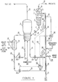
- the FCC process of the present invention comprises a reactor 1 , a regenerator 5 , a catalyst cooler 19 , and an extended reaction zone or riser 12 which provides a conversion zone.
- the catalyst circulation as well as the contact of the catalyst with the feed proceed according to the following description.
- regenerator 5 extends a pipe 6 which allows the passage of hot regenerated catalyst to the bottom 8 of riser 12 and a pipe 18 which allows the passage of hot regenerated catalyst to cooler 19 .
- a pipe 20 which is connected to pipe 24 provided with control valve 25 which conveys a portion of the cooled regenerated catalyst to the bottom 8 of riser 12 .
- Pipe 20 is also connected to pipe 21 , which by means of control valve 22 connected to pipe 23 conveys a portion of the cooled regenerated catalyst to the regenerator so as to cool the bed of the regenerator.
- a fluidizing lift gas introduced via a pipe 10 is made to contact the catalyst at the bottom 8 of the riser 12 , so as to keep the catalyst in a fluidized state.
- the distribution of the lift gas throughout the bottom 8 of the riser 12 is preferably effected thorough a perforated ring or else through a perforated plate which are distribution means well-known from the experts.
- the mixture of the hotter stream of catalyst and the cooler stream of catalyst occurs In the half height 9 of riser 12 .
- the ratio between the mixture of regenerated catalyst in portion 9 of riser 12 and the feedstock - stream 11 - which contacts the catalyst in the first portion of riser 12 is between 4 and 15, more preferably between 6 and 9.
- the feedstock can be introduced into the riser 12 at a higher temperature than that which is usually practiced in the state-of-the-art processes, so that the feedstock is quickly vaporized and in a more homogenously way than that usually practiced.
- the feedstock temperature which in the state-of-the-art is 240°C is increased to 360°C in the present invention.
- Mathematical simulation shows that this increase in temperature of the feedstock made up of atmospheric residue means an increase of more than 30% in the contact area between the catalyst and the feed spray provided by the feedstock atomizer.
- the temperature differential between the catalyst and the feed is also substantially lower than in the state-of-the-art processes, this being an additional positive effect by avoiding excess of localized heating of the feedstock.
- the combined two effects contribute to minimize the undesirable thermal cracking.
- the hot regenerated catalyst shows a temperature which is substantially higher than the relatively cold regenerated catalyst which leaves the cooler.
- the hot regenerated catalyst which leaves pipe 6 will normally be at a temperature in the range of 650 to 760°C and preferably in the range of 680 to 732°C.
- the cold regenerated catalyst which exits cooler 19 will normally be at a temperature in the range of 450 to 670°C and preferably in the range of 480 to 520°C.
- the ratio of hot regenerated catalyst to cooled regenerated catalyst which contacts the hydrocarbon feedstock in the riser is between 10:1 and 2:1, preferably between 6:1 and 4:1.
- the resulting temperature of the mixture of hot and cooled catalyst streams in the riser is in the range of 630 to 670°C, preferably between 640 and 660°C.
- the residence time of the catalyst particles in the riser varies between 0.3 and 8 seconds, preferably between 1 and 5 seconds.
- the riser is made up of portions 8 , 9 and 12 .
- Portion 12 provides a conversion zone for the cracking of the hydrocarbon feedstock.
- the conversion zone comprises a vertical pipe for pneumatic conveying of the mixture of a stream of hot regenerated catalyst from the regenerator and a stream of cooled regenerated catalyst from the catalyst cooler.
- the feedstock is introduced in the riser typically in the first portion of 12 by means of injection nozzles placed in stream 11 , which for the sake of simplicity are not described herein.
- the feedstock Before contacting the catalyst, the feedstock is at a temperature between 100 and 450°C, preferably between 240 and 360°C.
- the reaction temperature is monitored at the end of riser 12 , generally in the range between 510 and 570°C, preferably between 520 and 560°C.
- This control is effected by means of a well-known device 70 for measuring temperature which is associated to a monitor 71 and to a signal transmission device 72 which acts on control valve 7 .
- a well-known device 70 for measuring temperature which is associated to a monitor 71 and to a signal transmission device 72 which acts on control valve 7 .
- the monitor acts on the opening of valve 7 , so as to accordingly vary the flowrate of hot regenerated catalyst to be directed to the riser.
- the process of the present invention allows a change in the opening of valve 25 , so as to admit into the riser a modified flowrate of cooled regenerated catalyst so as to remake the previous catalyst/oil ratio.
- the reacted mixture made up of spent catalyst and the hydrocarbon vapours produced by the cracking reaction is then discharged from the end of the riser, carried through the separating catalyst device made up of parts 13 , 14 and 15 .
- the schematic representation of such separation device refers to a cyclone separator; however,any arrangement of separators may be employed to remove spent catalyst from the product hydrocarbon stream.
- the hydrocarbons flow to pipes 16 an d 28 , and are then directed to the fractioning section for recovery of the usual products of a catalytic cracking unit.
- the catalyst particles on which coke has been deposited flow through the bottom of devices 13 and 15 towards the containment vessel 1 wherefrom they reach an extension of the containment vessel 1 which is the stripper 2 , where counter-current steam removes the hydrocarbons which are adsorbed on the catalyst surface.
- the catalyst substantially free of hydrocarbon vapours leaves the stripping section through a pipe 3 .
- the flow of catalyst is controlled by a valve 4 , the opening of which is controlled by the stripper level.
- the spent stripped catalyst is conveyed through pipe 3 to regenerator 5 , so as to form a fluidized bed, where occurs the expected combustion of the coke deposited on the surface of the catalyst particles.
- Combustion is effected by contact with an oxygen gas, usually air, which enters regenerator 5 through an entrance at the bottom of the regenerator, stream 17 .
- Cyclone separators placed generally internally to the regenerator, for the sake of simplicity not represented, remove catalyst particles entrained by the combustion gas, rendering them to the catalyst bed before the exit of the gas.
- the combustion of coke from the catalyst particles heats the catalyst as well as the combustion gases.
- the catalyst cooler is an equipment external to the regenerator for removing heat from the regenerated catalyst by heat exchange with a fluid which is normally external to the process.
- the catalyst cooler 19 is linked to the regenerator 5 by means of a pipe 18 which conveys to the catalyst cooler 19 a flow of hot catalyst from the regenerator 5 .
- the catalyst cooler can be any state-of-the-art equipment for the thermal exchange involving fluidized solids and another fluid.
- the cold fluid will be boiler feed water, which in FIGURE 1 is represented by stream 26 , there occurring the generation of steam, fluid 27 .
- the catalyst cooler 19 plays a double role: to cool not only stream 21 of regenerated catalyst which returns to the regenerator 5 , but also the regenerated catalyst stream 24 which will be directed to the riser and which should crack the feedstock of heavy hydrocarbons.
- the control of the flowrate of the two streams is effected independently.
- the process concept suitable to the cracking of residual feedstocks comprises, besides stream 6 of hot regenerated catalyst from the regenerator 5 and directed to the riser, and stream 21 of cool regenerated catalyst which returns to the regenerator 5 , a stream 24 of cool regenerated catalyst bound to the riser, so that stream 24 and stream 6 form a mixture which is the catalyst stream which flows through portion 9 of the riser, this being the mixture with which the feedstock is effectively contacted.
- Portion 9 of the riser is long enough to secure that the heat balance between the two catalyst streams 24 and 6 be attained. Portion 9 is from 5 meters to 15 meters long, preferably from 7 meters to 10 meters long.
- a mixing fluid, stream 29 is injected in portion 9 this fluid being water, steam or any other gaseous fluid such as for instance fuel gas.
- the fluid is injected through nozzles which are radially placed, forming an angle of 30 to 60°, preferably 40 to 55°, with the cylindric wall of portion 9 .
- nozzles amount from 2 to 12, preferably from 4 to 8, according to the size of the unit, and are placed in the beginning of portion 9 , that is, at a short distance from the site where stream 6 is introduced.
- the exit rate of the mixing fluid through said nozzles is adjusted at a value which is sufficient to secure a suitable mixing energy.
- the flowrate of stream 29 is adjusted at a value which is sufficient to secure plug flow of catalyst through portion 9 , at moderate density.
- the ratio of this latter flowrate to the flowrate of gas lift injected into portion 8 of the riser is 80:20 to 60:40.
- the flowrate of the main catalyst stream 6 from regenerator 5 can be controlled by the temperature of the top of the riser while the flowrate of secondary catalyst stream 24 , from the catalyst cooler 19 and at a relatively lower temperature, in one mode can be controlled by the temperature of stream 9 .
- Stream 9 is the stream resulting from the mixture of hot regenerated catalyst stream and cooled regenerated catalyst.
- a state-of-the-art device 50 for the measurement of temperature coupled to a control device 51 transmit a signal by means of device 52 , through signal key 53 to control valve 25 .
- the flowrate of stream 24 will be controlled for example by means of a device which is sensitive to the pressure differential existing in the riser.
- state-of-the-art devices 60 and 61 for measuring pressure situated respectively at the beginning and at the end of portion 12 of the riser, coupled to a state-of-the-art control device 62 transmit a pressure differential signal through device 63 , through signal key 53 to device 52 and from then to valve 25 .
- the signal key 53 is a state-of-the-art device used in the instruments technique which makes possible to select the desired control mode of operation.
- the flowrate of stream 24 may be controlled by means of direct action of the operator on the valve opening, depending on the overall desired catalyst circulation.
- the flowrate of stream 24 may be controlled by any other method of flowrate control, since one of the main features of the present invention is the independent control of the flowrate of such stream, which consequently securing the independent control of the catalyst circulation.
- the temperature of the feedstock directed to the riser may be increased.
- the sum of the two effects that is, the reduction in temperature of the catalyst stream and the increase in temperature of the feedstock leads favourably to the minimization of the thermal cracking which in turn reduces the yield of fuel gas and coke, with the consequent increase in gasoline.
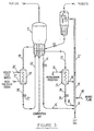
- a catalyst cooler may be used to exclusively cool the catalyst stream sent to the riser, while another catalyst cooler cools the catalyst stream which is recycled to the regenerator.
- the regenerated catalyst stream 18 ' is fed to catalyst cooler 19 ' which uses as cooling means a cold fluid which is typically boiler feed water.
- Cooled catalyst stream 20 ' crosses valve 22 ' and returns to regenerator 5 ' through pipe 23 ' keeping the regenerator vessel under temperature control.
- Stream 30 from regenerator 5 ' is fed to another catalyst cooler 35 transferring heat to a cold fluid 32 such as boiler feed water and thus generating high pressure steam 33 .
- this second mode advantageously offers the possibility of sending a stream of cooled catalyst to the reaction riser at a temperature which is different from the temperature of return of the cooled catalyst to the regenerator, with the consequent increased operation flexibility.
- the cooler which exclusively cools the catalyst stream sent to the riser can do it by means of the heat exchange between the catalyst and the hydrocarbon feedstock of the cracking unit.
- stream 18'' of regenerated catalyst is fed to a catalyst cooler 19'' which uses a cold fluid 26'' such as boiler feed water.
- the cooled catalyst stream returns through pipe 23'' to regenerator 5'' keeping this vessel under temperature control in a way which is similar to that illustrated in FIGURE 2 .
- Catalyst cooled stream 38 to riser 12'' is obtained passing stream 37 of regenerated catalyst through catalyst cooler 42 .
- the cooling medium is the feedstock itself, stream 35 which after receiving heat from the catalyst stream turns into stream 36 which on being injected into the riser contacts the catalyst mixture which rises through portion 9'' of the riser.
- Tests were effected in semi-industrial units as well as by simulation are listed in TABLE I below. These tests compare data of catalytic cracking for a residue feedstock of difficult crackability submitted to a state-of-the-art process as well as to a process according to the present invention. The main features of the feedstock are depicted in TABLE III .
- the yields listed in TABLE II show an increase of from 38.0 wt % to 39.7 wt% (4.5 wt %) in the gasoline yield, mainly as a result of a decrease of from 7.0 to 5.6 wt% (20 wt%) in the fuel gas yield.
Landscapes
- Chemical & Material Sciences (AREA)
- Oil, Petroleum & Natural Gas (AREA)
- Engineering & Computer Science (AREA)
- Chemical Kinetics & Catalysis (AREA)
- General Chemical & Material Sciences (AREA)
- Organic Chemistry (AREA)
- Production Of Liquid Hydrocarbon Mixture For Refining Petroleum (AREA)
Applications Claiming Priority (2)
| Application Number | Priority Date | Filing Date | Title |
|---|---|---|---|
| BR9703632 | 1997-07-17 | ||
| BR9703632A BR9703632A (pt) | 1997-07-17 | 1997-07-17 | Processo para craqueamento catalítico fluido de cargas pesadas |
Publications (2)
| Publication Number | Publication Date |
|---|---|
| EP0892031A2 true EP0892031A2 (de) | 1999-01-20 |
| EP0892031A3 EP0892031A3 (de) | 1999-03-31 |
Family
ID=36644840
Family Applications (1)
| Application Number | Title | Priority Date | Filing Date |
|---|---|---|---|
| EP97307435A Withdrawn EP0892031A3 (de) | 1997-07-17 | 1997-09-24 | Verfahren für das katalytische Wirbelschichtspalten von Schwerölen |
Country Status (6)
| Country | Link |
|---|---|
| US (1) | US6059958A (de) |
| EP (1) | EP0892031A3 (de) |
| JP (1) | JP4017221B2 (de) |
| CN (1) | CN1140608C (de) |
| BR (1) | BR9703632A (de) |
| CA (1) | CA2215584C (de) |
Cited By (4)
| Publication number | Priority date | Publication date | Assignee | Title |
|---|---|---|---|---|
| WO2000039250A1 (en) * | 1998-12-29 | 2000-07-06 | Petróleo Brasileiro S.A.-Petrobras | A process for the fluid catalytic cracking with pre-vaporized feed |
| FR2932495A1 (fr) * | 2008-06-17 | 2009-12-18 | Inst Francais Du Petrole | Dispositif de controle des conditions operatoires dans une unite de craquage catalytique a deux risers. |
| US10563129B2 (en) | 2015-09-25 | 2020-02-18 | Inaeris Technologies, Llc | Use of cooling media in biomass conversion process |
| US10619103B2 (en) | 2015-09-25 | 2020-04-14 | Inaeris Technologies, Llc | Catalyst addition to a circulating fluidized bed reactor |
Families Citing this family (17)
| Publication number | Priority date | Publication date | Assignee | Title |
|---|---|---|---|---|
| KR20030010364A (ko) * | 2001-07-26 | 2003-02-05 | 김동춘 | 촉매 하행식 크래킹반응 유화설비 및 이를 이용한휘발유·경유의 제조방법 |
| KR100517898B1 (ko) * | 2001-07-31 | 2005-09-30 | 김범진 | 폐합성수지를 원료로 하는 촉매 하행식 크래킹반응기 및 이를 이용한 휘발유·경유의 제조방법 |
| US6878656B2 (en) * | 2002-10-07 | 2005-04-12 | David B. Bartholic | Method for preparing a substitute for fresh fluid catalytic cracking catalyst |
| CN101210189B (zh) * | 2006-12-27 | 2012-01-25 | 中国石油化工股份有限公司 | 一种烃油转化过程中的换热方法和烃油转化方法 |
| CN101921611B (zh) * | 2009-06-12 | 2013-07-31 | 中国石油天然气股份有限公司 | 一种降低汽油硫含量的催化裂化方法及系统 |
| US20120298556A1 (en) * | 2010-02-11 | 2012-11-29 | Li Li | Method and equipment for circulating cooled regenerated catalyst |
| CN102268290B (zh) * | 2010-06-02 | 2014-03-26 | 中国石油化工集团公司 | 一种催化裂化方法及装置 |
| CN102942953B (zh) | 2012-11-07 | 2015-03-04 | 石宝珍 | 一种反应区催化剂控制和再生剂取热冷却方法 |
| CN104046387A (zh) * | 2013-03-11 | 2014-09-17 | 中石化洛阳工程有限公司 | 一种催化裂化工艺及装置 |
| FR3016370B1 (fr) * | 2014-01-10 | 2017-06-16 | Ifp Energies Now | Procede de craquage catalytique permettant une valorisation amelioree des calories des fumees de combustion. |
| CN105849235B (zh) | 2014-10-09 | 2017-11-03 | 石宝珍 | 一种催化裂化反应再生方法 |
| CN115011373A (zh) * | 2015-01-06 | 2022-09-06 | 李群柱 | 一种再生催化剂冷却方法及其设备 |
| CN106753511B (zh) * | 2015-11-25 | 2019-03-05 | 中国石化工程建设有限公司 | 补热器、催化裂解再生装置及外补热量的方法 |
| EP3284804B1 (de) * | 2016-08-19 | 2020-04-22 | INDIAN OIL CORPORATION Ltd. | Herstellung von propylen in einer fluid-catalytic-cracking-einheit |
| CN114080272B (zh) * | 2019-07-02 | 2025-11-07 | 鲁姆斯科技有限责任公司 | 流化催化裂化方法和装置 |
| FI20205240A1 (en) * | 2020-03-06 | 2021-09-07 | Valmet Automation Oy | A method for obtaining information on quality of combustion of a liquor in a chemical recovery boiler and a method for controlling a chemical recovery boiler |
| CN116712947B (zh) * | 2023-08-02 | 2024-02-06 | 罗托布斯特(上海)氢能科技有限公司 | 近海设施及船用可流动式原料气体催化热裂解系统及工艺 |
Family Cites Families (16)
| Publication number | Priority date | Publication date | Assignee | Title |
|---|---|---|---|---|
| US2819951A (en) * | 1955-02-23 | 1958-01-14 | Shell Dev | Apparatus for the regeneration of catalyst |
| US2970117A (en) * | 1957-05-10 | 1961-01-31 | Phillips Petroleum Co | Catalyst regeneration and apparatus therefor |
| US4167492A (en) * | 1976-10-12 | 1979-09-11 | Uop Inc. | Spent-catalyst combustion regeneration process with recycle of hot regenerated catalyst and spent catalyst |
| US4234411A (en) * | 1979-03-15 | 1980-11-18 | Uop Inc. | Fluid catalytic cracking process |
| US4257875A (en) * | 1979-05-29 | 1981-03-24 | Uop Inc. | Fluid catalytic cracking process |
| US4374750A (en) * | 1981-08-03 | 1983-02-22 | Uop Inc. | Fluid catalyst regeneration process and apparatus |
| US4396531A (en) * | 1981-08-13 | 1983-08-02 | Uop Inc. | Fluid catalyst regeneration process and apparatus |
| US4578366A (en) * | 1984-12-28 | 1986-03-25 | Uop Inc. | FCC combustion zone catalyst cooling process |
| US4614726A (en) * | 1985-06-21 | 1986-09-30 | Ashland Oil, Inc. | Process for cooling during regeneration of fluid cracking catalyst |
| US4757039A (en) * | 1987-02-24 | 1988-07-12 | Uop Inc. | Dual function heat withdrawal in a fluidized catalytic cracking-regeneration process |
| US5062945A (en) * | 1988-09-23 | 1991-11-05 | Mobil Oil Corporation | Method of FCC spent catalyst stripping for improved efficiency and reduced hydrocarbon flow to regenerator |
| US5000841A (en) * | 1989-04-10 | 1991-03-19 | Mobil Oil Corporation | Heavy oil catalytic cracking process and apparatus |
| US5346613A (en) * | 1993-09-24 | 1994-09-13 | Uop | FCC process with total catalyst blending |
| US5462652A (en) * | 1993-09-24 | 1995-10-31 | Uop | Short contact FCC process with catalyst blending |
| EP0724009A1 (de) * | 1995-01-30 | 1996-07-31 | Exxon Research And Engineering Company | Katalytischer Krackverfahren und Vorrichtung dazu |
| US5800697A (en) * | 1995-06-19 | 1998-09-01 | Uop Llc | FCC process with dual function catalyst cooling |
-
1997
- 1997-07-17 BR BR9703632A patent/BR9703632A/pt active Search and Examination
- 1997-09-16 CA CA002215584A patent/CA2215584C/en not_active Expired - Lifetime
- 1997-09-18 US US08/933,006 patent/US6059958A/en not_active Expired - Lifetime
- 1997-09-24 EP EP97307435A patent/EP0892031A3/de not_active Withdrawn
- 1997-10-07 CN CNB971193487A patent/CN1140608C/zh not_active Expired - Lifetime
- 1997-10-16 JP JP28348697A patent/JP4017221B2/ja not_active Expired - Lifetime
Cited By (9)
| Publication number | Priority date | Publication date | Assignee | Title |
|---|---|---|---|---|
| WO2000039250A1 (en) * | 1998-12-29 | 2000-07-06 | Petróleo Brasileiro S.A.-Petrobras | A process for the fluid catalytic cracking with pre-vaporized feed |
| US6558530B2 (en) | 1998-12-29 | 2003-05-06 | Petroleo Brasileiro S.A.-Petrobas | Process for the fluid catalytic cracking with pre-vaporized feed |
| FR2932495A1 (fr) * | 2008-06-17 | 2009-12-18 | Inst Francais Du Petrole | Dispositif de controle des conditions operatoires dans une unite de craquage catalytique a deux risers. |
| WO2009153441A3 (fr) * | 2008-06-17 | 2010-02-25 | Ifp | Dispositif de controle des conditions operatoires dans une unite de craquage catalytique a deux risers |
| CN102066528A (zh) * | 2008-06-17 | 2011-05-18 | Ifp新能源公司 | 用于在具有两个立管的催化裂化装置中控制操作条件的设备 |
| CN102066528B (zh) * | 2008-06-17 | 2013-09-25 | Ifp新能源公司 | 用于在具有两个立管的催化裂化装置中控制操作条件的设备 |
| US8957267B2 (en) | 2008-06-17 | 2015-02-17 | IFP Energies Nouvelles | Device for controlling the operating conditions in a catalytic cracking unit with two risers |
| US10563129B2 (en) | 2015-09-25 | 2020-02-18 | Inaeris Technologies, Llc | Use of cooling media in biomass conversion process |
| US10619103B2 (en) | 2015-09-25 | 2020-04-14 | Inaeris Technologies, Llc | Catalyst addition to a circulating fluidized bed reactor |
Also Published As
| Publication number | Publication date |
|---|---|
| CA2215584A1 (en) | 1999-01-17 |
| US6059958A (en) | 2000-05-09 |
| CN1140608C (zh) | 2004-03-03 |
| EP0892031A3 (de) | 1999-03-31 |
| JPH1150064A (ja) | 1999-02-23 |
| JP4017221B2 (ja) | 2007-12-05 |
| BR9703632A (pt) | 1999-02-23 |
| CA2215584C (en) | 2006-06-27 |
| CN1206036A (zh) | 1999-01-27 |
Similar Documents
| Publication | Publication Date | Title |
|---|---|---|
| US6059958A (en) | Process for the fluid catalytic cracking of heavy feedstocks | |
| EP0315179B1 (de) | Fluidisiertes katalytisches Krackverfahren mit extrem kurzer Kontaktzeit | |
| US4960503A (en) | Heating FCC feed in a backmix cooler | |
| US5597537A (en) | FCC feed contacting with catalyst recycle reactor | |
| JP4656689B2 (ja) | 流動触媒転換のためのライザ反応器 | |
| US4336160A (en) | Method and apparatus for cracking residual oils | |
| US4816137A (en) | Method for cracking residual oils | |
| US4601814A (en) | Method and apparatus for cracking residual oils | |
| EP1495090A2 (de) | Verfahren und apparat zur aufwertung eines fcc produktes in einem additionellen gut gemischten reaktor | |
| WO2003089546A1 (en) | Process and apparatus for upgrading fcc product with additional reactor with catalyst recycle | |
| US4356082A (en) | Heat balance in FCC process | |
| EP0315180B1 (de) | Verfahren und Einrichtung für die Fest/Flüssig-Trennung | |
| EP0908506B1 (de) | Verfahren und Vorrichtung zur fluitizierten katalytischen Spaltung | |
| US5215650A (en) | Cooling exothermic regenerator with endothermic reactions | |
| US6267873B1 (en) | Fluidized catalytic cracking process | |
| EP0236054A2 (de) | Verfahren zur Behandlung von Kohlenwasserstoffen | |
| EP1019461B1 (de) | KATALYTISCHES WIRBELSCHICHTKRACKVERFAHREN VON SCHWEREN EINSÄTZEN DURCH VERWENDUNG VON ABGESTREIFTEM KATALYSATOR ZUR VORWÄRMUNG DEs EINSATZes UND ZUR KONTROLLE DER REGENERATORTEMPERATUR | |
| US4716958A (en) | Method and apparatus for cooling fluid solid particles used in a regeneration system | |
| US5242577A (en) | Radial flow liquid sprayer for large size vapor flow lines and use thereof | |
| US9700865B2 (en) | Apparatuses and methods for cooling catalyst | |
| US4944845A (en) | Apparatus for upgrading liquid hydrocarbons | |
| US5205924A (en) | Transfer line quenching process and apparatus | |
| US5324418A (en) | FCC process using high cat:oil ratios | |
| EP0232259B1 (de) | Verfahren und vorrichtung zum kracken von restölen | |
| KR100257049B1 (ko) | 중질 원료의 유동 촉매 열분해 방법 |
Legal Events
| Date | Code | Title | Description |
|---|---|---|---|
| PUAI | Public reference made under article 153(3) epc to a published international application that has entered the european phase |
Free format text: ORIGINAL CODE: 0009012 |
|
| AK | Designated contracting states |
Kind code of ref document: A2 Designated state(s): DE FR GB IT NL |
|
| AX | Request for extension of the european patent |
Free format text: AL;LT;LV;RO;SI |
|
| PUAL | Search report despatched |
Free format text: ORIGINAL CODE: 0009013 |
|
| AK | Designated contracting states |
Kind code of ref document: A3 Designated state(s): AT BE CH DE DK ES FI FR GB GR IE IT LI LU MC NL PT SE |
|
| AX | Request for extension of the european patent |
Free format text: AL;LT;LV;RO;SI |
|
| 17P | Request for examination filed |
Effective date: 19990617 |
|
| AKX | Designation fees paid |
Free format text: DE FR GB IT NL |
|
| RAP3 | Party data changed (applicant data changed or rights of an application transferred) |
Owner name: PETROLEO BRASILEIRO S.A. - PETROBRAS |
|
| 17Q | First examination report despatched |
Effective date: 20010125 |
|
| GRAP | Despatch of communication of intention to grant a patent |
Free format text: ORIGINAL CODE: EPIDOSNIGR1 |
|
| STAA | Information on the status of an ep patent application or granted ep patent |
Free format text: STATUS: GRANT OF PATENT IS INTENDED |
|
| INTG | Intention to grant announced |
Effective date: 20190325 |
|
| STAA | Information on the status of an ep patent application or granted ep patent |
Free format text: STATUS: THE APPLICATION IS DEEMED TO BE WITHDRAWN |
|
| 18D | Application deemed to be withdrawn |
Effective date: 20190806 |