EP0892149A1 - Kühlsystem für den Vorderkantenbereich einer hohlen Gasturbinenschaufel - Google Patents
Kühlsystem für den Vorderkantenbereich einer hohlen Gasturbinenschaufel Download PDFInfo
- Publication number
- EP0892149A1 EP0892149A1 EP97810474A EP97810474A EP0892149A1 EP 0892149 A1 EP0892149 A1 EP 0892149A1 EP 97810474 A EP97810474 A EP 97810474A EP 97810474 A EP97810474 A EP 97810474A EP 0892149 A1 EP0892149 A1 EP 0892149A1
- Authority
- EP
- European Patent Office
- Prior art keywords
- ribs
- height
- cooling system
- blade
- front edge
- Prior art date
- Legal status (The legal status is an assumption and is not a legal conclusion. Google has not performed a legal analysis and makes no representation as to the accuracy of the status listed.)
- Granted
Links
Images

Classifications
-
- F—MECHANICAL ENGINEERING; LIGHTING; HEATING; WEAPONS; BLASTING
- F01—MACHINES OR ENGINES IN GENERAL; ENGINE PLANTS IN GENERAL; STEAM ENGINES
- F01D—NON-POSITIVE DISPLACEMENT MACHINES OR ENGINES, e.g. STEAM TURBINES
- F01D5/00—Blades; Blade-carrying members; Heating, heat-insulating, cooling or antivibration means on the blades or the members
- F01D5/12—Blades
- F01D5/14—Form or construction
- F01D5/18—Hollow blades, i.e. blades with cooling or heating channels or cavities; Heating, heat-insulating or cooling means on blades
- F01D5/187—Convection cooling
-
- F—MECHANICAL ENGINEERING; LIGHTING; HEATING; WEAPONS; BLASTING
- F05—INDEXING SCHEMES RELATING TO ENGINES OR PUMPS IN VARIOUS SUBCLASSES OF CLASSES F01-F04
- F05D—INDEXING SCHEME FOR ASPECTS RELATING TO NON-POSITIVE-DISPLACEMENT MACHINES OR ENGINES, GAS-TURBINES OR JET-PROPULSION PLANTS
- F05D2260/00—Function
- F05D2260/20—Heat transfer, e.g. cooling
- F05D2260/221—Improvement of heat transfer
- F05D2260/2214—Improvement of heat transfer by increasing the heat transfer surface
- F05D2260/22141—Improvement of heat transfer by increasing the heat transfer surface using fins or ribs
Definitions
- the invention relates to a cooling system for the leading edge area of a hollow Gas turbine blade, which extends from the blade root to the blade tip a longitudinally flowed channel extends in the area of the airfoil on the one hand from the inner walls of the front edge, the suction side and the Pressure side and on the other hand from a connecting the pressure side with the suction side Web is limited, the inner walls of the suction side and the Print page with a plurality of oblique and at least approximately parallel Ribs are provided, and the suction side above the blade height Ribs and the pressure-side ribs are offset from one another.
- the invention thus relates generally to a system for cooling a curved wall, which on one side of a hot medium and on a coolant flows around its other side.
- Cooling poses a particular problem of the leading edge area of such blades.
- a cooling system of the type mentioned is known from DE-C2 32 48 162.
- the area under consideration is equipped with ribs on its inner walls, which are radially outwards from the leading edge to the web. These ribs have a height that is anywhere between 10% and 33% of the local Height of the coolant channel is. This is also intended for a narrow channel Effective cooling of the leading edge area.
- the ribs to trigger turbulence and promotion provided, and the cooling fluid should be without large Resistance to be conducted through the blade. Due to the oblique arrangement of the Ribs in a defined direction are to be created on the ribs have a speed component towards the front edge.
- This is the actual front edge is rib-free. It has one on the inside cylindrical shape with a radius that is about the height of the subsequent Ribs corresponds. The distance between the ribs and the leading edge has a value between one to five times the height of the ribs.
- the present invention has for its object a cooling system of the beginning to create the type mentioned, by increasing the turbulence in the leading edge area and other measures, a considerable increase in Heat transfer coefficients can be achieved.
- the ratio of the height of the ribs to the local one Height of the channel increases from the front edge towards the web or over the length of the ribs is constant.
- a further relief of the web area is achieved if - again in contrast to the prior art mentioned at the beginning - the height of the ribs in the area of the web is reduced early so that the rib does not reach Bridge is enough.
- the turbulence then missing in this area has an advantageous effect reduced cooling of the web in the connection area.
- the cast blade shown in Fig. 1 has three inner chambers a, b, and c on that from a coolant, such as steam or air, perpendicular to Flow through the drawing plane.
- a coolant such as steam or air
- the inside of the blade contour forming wall W - hot gases flow around it on both sides is - the coolant flows around and give off their heat to the coolant.
- numerous are not here at least in the two front chambers a, b shown tools such as guide ribs, flow channels, inserts for impingement cooling and the like can be provided to improve wall cooling.
- the coolant circulates in a closed circuit, by which is meant is that neither on the front edge, the suction side, the pressure side nor in the Blowing out coolant into the flow channel in the area of the rear edge he follows.
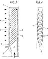
- FIG. 2 and 3 show the cooling system for the leading edge area of a hollow Gas turbine blade. It extends from the blade root 1 to the blade tip 2 a longitudinally flowed channel 3, which corresponds to chamber a in FIG. 1. in the Area of the airfoil 4 is this channel from the inner walls of the Front edge, the suction side 6 and the pressure side 7 and one of the pressure side limited with web 8 connecting the suction side.
- the inner walls of the The suction side and the pressure side are inclined with a plurality and at least Provided approximately parallel ribs 9, which are above the blade height are staggered. As from the schematic representation in FIG. 3 The ribs on the suction side and the pressure side are visible above the bucket height Ribs offset by half a division.
- the rib structure creates a secondary flow in the duct, the warm air transported from the immediate area of the leading edge to the center of the channel. This warm air is replaced by colder air from the center of the duct.
- the ribs in the leading edge area are tighter than in the Middle area of the canal. This leads to a very strong increase in heat transfer in this area by increasing turbulence and by Generation of investment points of the flow behind recirculation areas that arise behind the ribs.
- the ratio of the height h of the ribs to the local height H of the channel 3 decreases from the leading edge 5 towards web 8. This increase in height is shown in the example chosen so that between the front edge and web in each axial plane a free flow channel around the same width. With this measure an even coolant distribution over the entire cross-section flowed through reached. Only by introducing a location-dependent rib height the two previously mentioned mechanisms for increasing the Heat transfer particularly effective. The locally location-dependent rib height creates a flow in the channel that also in the narrow leading edge area flows because the flow resistances are now about the same as in the remaining channel.
- the design of the new ribs also affects the Cooling passage very positive and supportive of the secondary flow mentioned above in the duct, which the air from the leading edge to the rear Creates channel area.
- the high ribs in the rear channel area induce here a very strong secondary flow.
- the height h of the ribs increases in the area of the web 8 steadily towards zero. It goes without saying that, due to the manufacturing process, sharp-edged Connections are hardly possible. As already mentioned, this configuration the advantage that at the junction of the web with the inner walls the coolant flows along the walls almost without interference and thus less cooling effect developed. Of course, the intermediate bridge 8 may never get too hot. Should this be due to the configuration selected can occur, there is easily the possibility of the ribs up to Continuing the web with an adjusted height, i.e. with the same or reduced Height.
- the height h of the individual ribs staggered above the blade height can of course be adapted to the local heat load.
- a Enlargement of the ribs towards the tip of the blade is particularly then attached when the coolant passes through the channel has already warmed up strongly, so that the required temperature difference between wall to be cooled and coolant for the desired heat exchange smaller becomes.
- a similar effect can be achieved by spacing the ribs across the bucket height is made variable. Of course, both can also Measures are combined.
- Such a variable distance is shown schematically in Fig. 5 illustrates. The distance between the ribs and the tip of the blade is shown in the upper part increasingly larger. In the lower part the solution is shown, in which the Slant runs directly into the front edge, i.e. the distance d mentioned is here 0.
Landscapes
- Engineering & Computer Science (AREA)
- Mechanical Engineering (AREA)
- General Engineering & Computer Science (AREA)
- Turbine Rotor Nozzle Sealing (AREA)
Abstract
Description
- Fig. 1
- eine Schaufel im Querschnitt;
- Fig. 2
- den Vorderkantenbereich der Schaufel nach Fig. 1;
- Fig. 3
- einen Längsschnitt durch den Vorderkantenbereich;
- Fig. 4
- eine perspektivische schematische Vorderansicht der Schaufelberippung im Vorderkantenbereich.
- Fig. 5
- eine schematische Abwicklung der Schaufelberippung im Vorderkantenbereich.
- a, b, c
- Innenkammern der Schaufel
- W
- Schaufelwand
- 1
- Schaufelfuss
- 2
- Schaufelspitze
- 3
- längsdurchströmter Kanal
- 4
- Schaufelblatt
- 5
- Vorderkante
- 6
- Saugseite
- 7
- Druckseite
- 8
- Steg
- 9
- Rippe
- h
- Höhe der Rippe
- H
- örtliche Breite des Kanals 3
- d
- Abstand zwischen 5 und Umlenkung
Claims (8)
- Kühlsystem für den Vorderkantenbereich einer hohlen Gasturbinenschaufel, bei welcher sich vom Schaufelfuss (1) bis zur Schaufelspitze (2) ein längsdurchströmter Kanal (3) erstreckt, welcher im Bereich des Schaufelblattes (4) einerseits von den Innenwandungen der Vorderkante (5), der Saugseite (6) und der Druckseite (7) und andererseits von einem die Druckseite mit der Saugseite verbindenden Steg (8) begrenzt ist, wobei die Innenwandungen der Saugseite und der Druckseite mit einer Mehrzahl schräg und zumindest annähernd parallel verlaufender Rippen (9) versehen sind, und wobei über der Schaufelhöhe die saugseitigen Rippen und die druckseitigen Rippen (um eine halbe Teilung) gegeneinander versetzt sind,
dadurch gekennzeichnet, dass die Rippen (9) vom Steg (8) in Richtung Vorderkante (5) radial einwärts verlaufen, im Bereich der Vorderkante in die Radiale übergehen und um die Vorderkante herumgeführt sind. - Kühlsystem nach Anspruch 1, dadurch gekennzeichnet, dass die Umlenkung der Rippen (9) von der Schrägen in die Radiale mit kleinstmöglichem Radius erfolgt.
- Kühlsystem nach Anspruch 1, dadurch gekennzeichnet, dass der Abstand (d) von der Vorderkante (5) zum Ort der Umlenkung zwischen 0% und 15% der Länge des Kanals (3) beträgt.
- Kühlsystem nach Anspruch 1, dadurch gekennzeichnet, dass die Höhe (h) der Rippen (9) von der Vorderkante (5) in Richtung Steg (8) zunimmt.
- Kühlsystem nach Anspruch 1, dadurch gekennzeichnet, dass das Verhältnis Höhe (h) der Rippen (9) zur örtlichen Höhe (H) des Kanals (4) über die Längserstreckung der Rippen konstant ist.
- Kühlsystem nach Anspruch 1, dadurch gekennzeichnet, dass die Höhe (h) der Rippen (9) im Bereich des Steges (8) abnimmt.
- Kühlsystem nach Anspruch 1, dadurch gekennzeichnet, dass die Höhe h der Rippen (9) über der Schaufelhöhe variabel ist.
- Kühlsystem nach Anspruch 1, dadurch gekennzeichnet,. dass die Teilung der Rippen (9) zueinander über der Schaufelhöhe variabel ist.
Priority Applications (3)
| Application Number | Priority Date | Filing Date | Title |
|---|---|---|---|
| EP97810474A EP0892149B1 (de) | 1997-07-14 | 1997-07-14 | Kühlsystem für den Vorderkantenbereich einer hohlen Gasturbinenschaufel |
| DE59709195T DE59709195D1 (de) | 1997-07-14 | 1997-07-14 | Kühlsystem für den Vorderkantenbereich einer hohlen Gasturbinenschaufel |
| US09/111,706 US6068445A (en) | 1997-07-14 | 1998-07-08 | Cooling system for the leading-edge region of a hollow gas-turbine blade |
Applications Claiming Priority (1)
| Application Number | Priority Date | Filing Date | Title |
|---|---|---|---|
| EP97810474A EP0892149B1 (de) | 1997-07-14 | 1997-07-14 | Kühlsystem für den Vorderkantenbereich einer hohlen Gasturbinenschaufel |
Publications (2)
| Publication Number | Publication Date |
|---|---|
| EP0892149A1 true EP0892149A1 (de) | 1999-01-20 |
| EP0892149B1 EP0892149B1 (de) | 2003-01-22 |
Family
ID=8230296
Family Applications (1)
| Application Number | Title | Priority Date | Filing Date |
|---|---|---|---|
| EP97810474A Expired - Lifetime EP0892149B1 (de) | 1997-07-14 | 1997-07-14 | Kühlsystem für den Vorderkantenbereich einer hohlen Gasturbinenschaufel |
Country Status (3)
| Country | Link |
|---|---|
| US (1) | US6068445A (de) |
| EP (1) | EP0892149B1 (de) |
| DE (1) | DE59709195D1 (de) |
Cited By (3)
| Publication number | Priority date | Publication date | Assignee | Title |
|---|---|---|---|---|
| EP2392775A1 (de) * | 2010-06-07 | 2011-12-07 | Siemens Aktiengesellschaft | Rotationsschaufel zur Verwendung in einem Fluidstrom einer Turbine und zugehörige Turbine |
| DE10316909B4 (de) * | 2002-05-16 | 2016-01-07 | Alstom Technology Ltd. | Kühlbares Turbinenblatt mit Rippen im Kühlkanal |
| US9388700B2 (en) | 2012-03-16 | 2016-07-12 | United Technologies Corporation | Gas turbine engine airfoil cooling circuit |
Families Citing this family (17)
| Publication number | Priority date | Publication date | Assignee | Title |
|---|---|---|---|---|
| US6406260B1 (en) * | 1999-10-22 | 2002-06-18 | Pratt & Whitney Canada Corp. | Heat transfer promotion structure for internally convectively cooled airfoils |
| US6554571B1 (en) * | 2001-11-29 | 2003-04-29 | General Electric Company | Curved turbulator configuration for airfoils and method and electrode for machining the configuration |
| US6672836B2 (en) | 2001-12-11 | 2004-01-06 | United Technologies Corporation | Coolable rotor blade for an industrial gas turbine engine |
| GB0222352D0 (en) * | 2002-09-26 | 2002-11-06 | Dorling Kevin | Turbine blade turbulator cooling design |
| US8690538B2 (en) * | 2006-06-22 | 2014-04-08 | United Technologies Corporation | Leading edge cooling using chevron trip strips |
| US20070297916A1 (en) | 2006-06-22 | 2007-12-27 | United Technologies Corporation | Leading edge cooling using wrapped staggered-chevron trip strips |
| EP1921269A1 (de) * | 2006-11-09 | 2008-05-14 | Siemens Aktiengesellschaft | Turbinenschaufel |
| US8083485B2 (en) * | 2007-08-15 | 2011-12-27 | United Technologies Corporation | Angled tripped airfoil peanut cavity |
| US8376706B2 (en) * | 2007-09-28 | 2013-02-19 | General Electric Company | Turbine airfoil concave cooling passage using dual-swirl flow mechanism and method |
| US9334755B2 (en) * | 2012-09-28 | 2016-05-10 | United Technologies Corporation | Airfoil with variable trip strip height |
| EP2954168B1 (de) | 2013-02-05 | 2019-07-03 | United Technologies Corporation | Gasturbinenmotorkomponente mit gekrümmtem turbulator |
| EP2971544B1 (de) * | 2013-03-14 | 2019-08-21 | United Technologies Corporation | Kühlung einer gasturbinenmotorkomponente mit verschachtelten, gegenüberliegenden nockenstreifen |
| US10358978B2 (en) | 2013-03-15 | 2019-07-23 | United Technologies Corporation | Gas turbine engine component having shaped pedestals |
| JP6245740B2 (ja) * | 2013-11-20 | 2017-12-13 | 三菱日立パワーシステムズ株式会社 | ガスタービン翼 |
| US10119404B2 (en) * | 2014-10-15 | 2018-11-06 | Honeywell International Inc. | Gas turbine engines with improved leading edge airfoil cooling |
| US10406596B2 (en) | 2015-05-01 | 2019-09-10 | United Technologies Corporation | Core arrangement for turbine engine component |
| US10352177B2 (en) | 2016-02-16 | 2019-07-16 | General Electric Company | Airfoil having impingement openings |
Citations (4)
| Publication number | Priority date | Publication date | Assignee | Title |
|---|---|---|---|---|
| GB2112467A (en) * | 1981-12-28 | 1983-07-20 | United Technologies Corp | Coolable airfoil for a rotary machine |
| GB2159585A (en) * | 1984-05-24 | 1985-12-04 | Gen Electric | Turbine blade |
| EP0230917A2 (de) * | 1986-01-20 | 1987-08-05 | Hitachi, Ltd. | Gekühlte Gasturbinenschaufel |
| EP0527554A1 (de) * | 1991-07-04 | 1993-02-17 | Hitachi, Ltd. | Turbinenschaufel mit Innenkühlungskanal |
-
1997
- 1997-07-14 DE DE59709195T patent/DE59709195D1/de not_active Expired - Lifetime
- 1997-07-14 EP EP97810474A patent/EP0892149B1/de not_active Expired - Lifetime
-
1998
- 1998-07-08 US US09/111,706 patent/US6068445A/en not_active Expired - Lifetime
Patent Citations (4)
| Publication number | Priority date | Publication date | Assignee | Title |
|---|---|---|---|---|
| GB2112467A (en) * | 1981-12-28 | 1983-07-20 | United Technologies Corp | Coolable airfoil for a rotary machine |
| GB2159585A (en) * | 1984-05-24 | 1985-12-04 | Gen Electric | Turbine blade |
| EP0230917A2 (de) * | 1986-01-20 | 1987-08-05 | Hitachi, Ltd. | Gekühlte Gasturbinenschaufel |
| EP0527554A1 (de) * | 1991-07-04 | 1993-02-17 | Hitachi, Ltd. | Turbinenschaufel mit Innenkühlungskanal |
Cited By (7)
| Publication number | Priority date | Publication date | Assignee | Title |
|---|---|---|---|---|
| DE10316909B4 (de) * | 2002-05-16 | 2016-01-07 | Alstom Technology Ltd. | Kühlbares Turbinenblatt mit Rippen im Kühlkanal |
| EP2392775A1 (de) * | 2010-06-07 | 2011-12-07 | Siemens Aktiengesellschaft | Rotationsschaufel zur Verwendung in einem Fluidstrom einer Turbine und zugehörige Turbine |
| WO2011154195A1 (en) * | 2010-06-07 | 2011-12-15 | Siemens Aktiengesellschaft | Cooled vane of a turbine and corresponding turbine |
| CN102918229A (zh) * | 2010-06-07 | 2013-02-06 | 西门子公司 | 涡轮机的冷却翼片和相应的涡轮机 |
| CN102918229B (zh) * | 2010-06-07 | 2016-04-27 | 西门子公司 | 涡轮机的冷却翼片和相应的涡轮机 |
| US9822643B2 (en) | 2010-06-07 | 2017-11-21 | Siemens Aktiengesellschaft | Cooled vane of a turbine and corresponding turbine |
| US9388700B2 (en) | 2012-03-16 | 2016-07-12 | United Technologies Corporation | Gas turbine engine airfoil cooling circuit |
Also Published As
| Publication number | Publication date |
|---|---|
| DE59709195D1 (de) | 2003-02-27 |
| US6068445A (en) | 2000-05-30 |
| EP0892149B1 (de) | 2003-01-22 |
Similar Documents
| Publication | Publication Date | Title |
|---|---|---|
| EP0892149B1 (de) | Kühlsystem für den Vorderkantenbereich einer hohlen Gasturbinenschaufel | |
| DE60017437T2 (de) | Rippen zur erhöhung der wärmeübertragung einer mittels kühlluft innengekühlten turbinenschaufel | |
| DE602005000449T2 (de) | Kühlung mit Mikrokanälen für eine Turbinenschaufel | |
| DE69930916T2 (de) | Hohle Gasturbinenschaufel | |
| EP1113145B1 (de) | Schaufel für Gasturbinen mit Drosselquerschnitt an Hinterkante | |
| DE60031185T2 (de) | Methode zur Kühlung einer Wand einer Strömungsmaschinenschaufel | |
| DE69910913T2 (de) | Kühlbare Schaufel für Gasturbinen | |
| EP1223308B1 (de) | Komponente einer Strömungsmaschine | |
| DE69822100T2 (de) | Turbinenschaufel | |
| DE60015233T2 (de) | Turbinenschaufel mit interner Kühlung | |
| EP0964981B1 (de) | Turbinenschaufel sowie deren verwendung in einer gasturbinenanlage | |
| CH697919B1 (de) | Turbinenblatt mit konkavem Kühlströmungskanal und darin angeordneten, entgegengesetzte Drallströme bewirkenden Turbulatoren. | |
| EP1267039A1 (de) | Kühlkonstruktion für Schaufelblatthinterkante | |
| EP1165939B1 (de) | Kühlmitteldurchströmte, gegossene gasturbinenschaufel sowie vorrichtung und verfahren zur herstellung eines verteilerraums der gasturbinenschaufel | |
| WO2010015433A1 (de) | Wärmeübertragungseinheit für eine verbrennungskraftmaschine | |
| DE2241194A1 (de) | Stroemungsmaschinenschaufel mit tragfluegelfoermigem querschnittsprofil und mit einer vielzahl von in schaufellaengsrichtung verlaufenden kuehlkanaelen | |
| EP3564483A1 (de) | Schaufelblatt für eine turbinenschaufel | |
| DE3518314A1 (de) | Turbinenschaufel | |
| DE19634238A1 (de) | Kühlbare Schaufel | |
| EP0892150B1 (de) | Kühlsystem für den Hinterkantenbereich einer hohlen Gasturbinenschaufel | |
| EP1126136A2 (de) | Turbinenschaufel mit luftgekühltem Deckbandelement | |
| DE202006009464U1 (de) | Wärmetauscher | |
| DE102017110051A1 (de) | Schaufel mit belastungsreduzierendem bauchigem Vorsprung an einer Wendeöffnung von Kühlmittelkanälen | |
| DE112020004602B4 (de) | Turbinenflügel | |
| WO2003054356A1 (de) | Thermisch belastetes bauteil |
Legal Events
| Date | Code | Title | Description |
|---|---|---|---|
| PUAI | Public reference made under article 153(3) epc to a published international application that has entered the european phase |
Free format text: ORIGINAL CODE: 0009012 |
|
| AK | Designated contracting states |
Kind code of ref document: A1 Designated state(s): DE |
|
| AX | Request for extension of the european patent |
Free format text: AL;LT;LV;RO;SI |
|
| 17P | Request for examination filed |
Effective date: 19990619 |
|
| AKX | Designation fees paid |
Free format text: DE |
|
| RAP1 | Party data changed (applicant data changed or rights of an application transferred) |
Owner name: ALSTOM |
|
| GRAG | Despatch of communication of intention to grant |
Free format text: ORIGINAL CODE: EPIDOS AGRA |
|
| 17Q | First examination report despatched |
Effective date: 20020128 |
|
| GRAG | Despatch of communication of intention to grant |
Free format text: ORIGINAL CODE: EPIDOS AGRA |
|
| GRAG | Despatch of communication of intention to grant |
Free format text: ORIGINAL CODE: EPIDOS AGRA |
|
| GRAH | Despatch of communication of intention to grant a patent |
Free format text: ORIGINAL CODE: EPIDOS IGRA |
|
| GRAH | Despatch of communication of intention to grant a patent |
Free format text: ORIGINAL CODE: EPIDOS IGRA |
|
| RAP1 | Party data changed (applicant data changed or rights of an application transferred) |
Owner name: ALSTOM (SWITZERLAND) LTD |
|
| GRAA | (expected) grant |
Free format text: ORIGINAL CODE: 0009210 |
|
| RIN1 | Information on inventor provided before grant (corrected) |
Inventor name: WU, PEY-SHEY, DR. Inventor name: WEIGAND, BERNHARD, DR. Inventor name: JOHNSON, BRUCE, DR. Inventor name: BEECK, ALEXANDER, DR. |
|
| AK | Designated contracting states |
Kind code of ref document: B1 Designated state(s): DE |
|
| REF | Corresponds to: |
Ref document number: 59709195 Country of ref document: DE Date of ref document: 20030227 Kind code of ref document: P |
|
| PLBE | No opposition filed within time limit |
Free format text: ORIGINAL CODE: 0009261 |
|
| STAA | Information on the status of an ep patent application or granted ep patent |
Free format text: STATUS: NO OPPOSITION FILED WITHIN TIME LIMIT |
|
| 26N | No opposition filed |
Effective date: 20031023 |
|
| REG | Reference to a national code |
Ref country code: DE Ref legal event code: R082 Ref document number: 59709195 Country of ref document: DE Representative=s name: UWE ROESLER, DE |
|
| REG | Reference to a national code |
Ref country code: DE Ref legal event code: R082 Ref document number: 59709195 Country of ref document: DE Representative=s name: ROESLER, UWE, DIPL.-PHYS.UNIV., DE Effective date: 20120713 Ref country code: DE Ref legal event code: R081 Ref document number: 59709195 Country of ref document: DE Owner name: GENERAL ELECTRIC TECHNOLOGY GMBH, CH Free format text: FORMER OWNER: ALSTOM (SWITZERLAND) LTD., BADEN, CH Effective date: 20120713 Ref country code: DE Ref legal event code: R081 Ref document number: 59709195 Country of ref document: DE Owner name: ALSTOM TECHNOLOGY LTD., CH Free format text: FORMER OWNER: ALSTOM (SWITZERLAND) LTD., BADEN, CH Effective date: 20120713 |
|
| REG | Reference to a national code |
Ref country code: DE Ref legal event code: R082 Ref document number: 59709195 Country of ref document: DE Representative=s name: ROESLER, UWE, DIPL.-PHYS.UNIV., DE Ref country code: DE Ref legal event code: R081 Ref document number: 59709195 Country of ref document: DE Owner name: GENERAL ELECTRIC TECHNOLOGY GMBH, CH Free format text: FORMER OWNER: ALSTOM TECHNOLOGY LTD., BADEN, CH |
|
| PGFP | Annual fee paid to national office [announced via postgrant information from national office to epo] |
Ref country code: DE Payment date: 20160722 Year of fee payment: 20 |
|
| REG | Reference to a national code |
Ref country code: DE Ref legal event code: R071 Ref document number: 59709195 Country of ref document: DE |