EP0892225A2 - Appareil de conditionnement d'air et ses composants - Google Patents
Appareil de conditionnement d'air et ses composants Download PDFInfo
- Publication number
- EP0892225A2 EP0892225A2 EP98112577A EP98112577A EP0892225A2 EP 0892225 A2 EP0892225 A2 EP 0892225A2 EP 98112577 A EP98112577 A EP 98112577A EP 98112577 A EP98112577 A EP 98112577A EP 0892225 A2 EP0892225 A2 EP 0892225A2
- Authority
- EP
- European Patent Office
- Prior art keywords
- condenser
- unit according
- sorption
- sorption unit
- evaporator
- Prior art date
- Legal status (The legal status is an assumption and is not a legal conclusion. Google has not performed a legal analysis and makes no representation as to the accuracy of the status listed.)
- Granted
Links
Images


Classifications
-
- F—MECHANICAL ENGINEERING; LIGHTING; HEATING; WEAPONS; BLASTING
- F25—REFRIGERATION OR COOLING; COMBINED HEATING AND REFRIGERATION SYSTEMS; HEAT PUMP SYSTEMS; MANUFACTURE OR STORAGE OF ICE; LIQUEFACTION SOLIDIFICATION OF GASES
- F25B—REFRIGERATION MACHINES, PLANTS OR SYSTEMS; COMBINED HEATING AND REFRIGERATION SYSTEMS; HEAT PUMP SYSTEMS
- F25B39/00—Evaporators; Condensers
-
- F—MECHANICAL ENGINEERING; LIGHTING; HEATING; WEAPONS; BLASTING
- F24—HEATING; RANGES; VENTILATING
- F24F—AIR-CONDITIONING; AIR-HUMIDIFICATION; VENTILATION; USE OF AIR CURRENTS FOR SCREENING
- F24F5/00—Air-conditioning systems or apparatus not covered by F24F1/00 or F24F3/00, e.g. using solar heat or combined with household units such as an oven or water heater
- F24F5/0007—Air-conditioning systems or apparatus not covered by F24F1/00 or F24F3/00, e.g. using solar heat or combined with household units such as an oven or water heater cooling apparatus specially adapted for use in air-conditioning
- F24F5/0014—Air-conditioning systems or apparatus not covered by F24F1/00 or F24F3/00, e.g. using solar heat or combined with household units such as an oven or water heater cooling apparatus specially adapted for use in air-conditioning using absorption or desorption
-
- F—MECHANICAL ENGINEERING; LIGHTING; HEATING; WEAPONS; BLASTING
- F25—REFRIGERATION OR COOLING; COMBINED HEATING AND REFRIGERATION SYSTEMS; HEAT PUMP SYSTEMS; MANUFACTURE OR STORAGE OF ICE; LIQUEFACTION SOLIDIFICATION OF GASES
- F25B—REFRIGERATION MACHINES, PLANTS OR SYSTEMS; COMBINED HEATING AND REFRIGERATION SYSTEMS; HEAT PUMP SYSTEMS
- F25B17/00—Sorption machines, plants or systems, operating intermittently, e.g. absorption or adsorption type
- F25B17/08—Sorption machines, plants or systems, operating intermittently, e.g. absorption or adsorption type the absorbent or adsorbent being a solid, e.g. salt
- F25B17/086—Sorption machines, plants or systems, operating intermittently, e.g. absorption or adsorption type the absorbent or adsorbent being a solid, e.g. salt with two or more boiler-sorber/evaporator units
-
- F—MECHANICAL ENGINEERING; LIGHTING; HEATING; WEAPONS; BLASTING
- F25—REFRIGERATION OR COOLING; COMBINED HEATING AND REFRIGERATION SYSTEMS; HEAT PUMP SYSTEMS; MANUFACTURE OR STORAGE OF ICE; LIQUEFACTION SOLIDIFICATION OF GASES
- F25B—REFRIGERATION MACHINES, PLANTS OR SYSTEMS; COMBINED HEATING AND REFRIGERATION SYSTEMS; HEAT PUMP SYSTEMS
- F25B35/00—Boiler-absorbers, i.e. boilers usable for absorption or adsorption
- F25B35/04—Boiler-absorbers, i.e. boilers usable for absorption or adsorption using a solid as sorbent
-
- Y—GENERAL TAGGING OF NEW TECHNOLOGICAL DEVELOPMENTS; GENERAL TAGGING OF CROSS-SECTIONAL TECHNOLOGIES SPANNING OVER SEVERAL SECTIONS OF THE IPC; TECHNICAL SUBJECTS COVERED BY FORMER USPC CROSS-REFERENCE ART COLLECTIONS [XRACs] AND DIGESTS
- Y02—TECHNOLOGIES OR APPLICATIONS FOR MITIGATION OR ADAPTATION AGAINST CLIMATE CHANGE
- Y02A—TECHNOLOGIES FOR ADAPTATION TO CLIMATE CHANGE
- Y02A30/00—Adapting or protecting infrastructure or their operation
- Y02A30/27—Relating to heating, ventilation or air conditioning [HVAC] technologies
-
- Y—GENERAL TAGGING OF NEW TECHNOLOGICAL DEVELOPMENTS; GENERAL TAGGING OF CROSS-SECTIONAL TECHNOLOGIES SPANNING OVER SEVERAL SECTIONS OF THE IPC; TECHNICAL SUBJECTS COVERED BY FORMER USPC CROSS-REFERENCE ART COLLECTIONS [XRACs] AND DIGESTS
- Y02—TECHNOLOGIES OR APPLICATIONS FOR MITIGATION OR ADAPTATION AGAINST CLIMATE CHANGE
- Y02B—CLIMATE CHANGE MITIGATION TECHNOLOGIES RELATED TO BUILDINGS, e.g. HOUSING, HOUSE APPLIANCES OR RELATED END-USER APPLICATIONS
- Y02B30/00—Energy efficient heating, ventilation or air conditioning [HVAC]
- Y02B30/62—Absorption based systems
Definitions
- the invention relates to a sorption unit according to the preamble of the claim 1, a buffer device according to the preamble of claim 19, a Condenser / evaporator unit according to the preamble of claim 15 or 27 and an air conditioning device which is formed from these elements, according to the preamble of claim 37.
- air conditioning rooms are, on the one hand, to constantly renew the air and on the other hand the creation of a defined temperature and climate condition, i.e. regulation of air temperature, air humidity and / or Filtering.
- air conditioning in the sense of the present invention is it primarily a temperature change, be it by a "Air conditioning" for cooling, a heat pump system or another application.
- processes are currently used for temperature air conditioning for use in which the sorption process takes place by cooling a sorption part is initiated and a working fluid evaporates in an evaporator becomes.
- the working fluid is sorbed exothermic in a sorbent and in a subsequent endothermic reaction (regeneration phase) again sorbed.
- the device used to carry out this method is in DE 42 33 062 described and consists essentially of several elongated Sorption containers (Kocheradsorberteil) that over part of their length with Zeolite serving as sorbent are filled and in this part an adsorber form.
- the other part of the length forms a condenser evaporator zone (Evaporator).
- the sorption containers rotate in two coaxial housings a circular path and are located with the Kocheradsorberteil in one Housing and with the evaporator part in the other housing.
- the Kocheradsorbermaschinesing housing has an inlet and an outlet for a gaseous heat transfer medium so that the heat transfer medium on its flow path through the housing both the Kocheradsorbermaschine Extracts heat as well as supplying heat.
- the Kocheradsorberteil has curved, elongated, flat in cross section Hollow body made of an approximately 0.1 mm thick stainless steel sheet are, the top of these sheets is smooth.
- the undersides are wavy curved sheets arranged.
- the sheets are on the apex lines of the Waves by roll welds or by laser treatment with each other connected.
- the approx. 600 mm long and approx. 80 mm wide sheets are made of zeolite coated, the zeolite layer being produced in a multi-layer application process is applied.
- the arches touch the smooth stainless steel sheet and thereby support it. This shape creates channels through which water vapor is passed.
- the problems further worsen the air conditioner in the evaporator area.
- the generic evaporator - as well as the temperature insulating Area between evaporator and sorption zone (buffer device called) - have the problem that not enough prevented is that even larger water droplets during the adsorption of water in the zeolite are entrained by the evaporator into the sorption unit, so that then Water droplets could enter the zeolite fraction directly. This worsens the efficiency of the air conditioner because the water droplets do not heat from the room surrounding the evaporator.
- the invention is therefore aimed at the generic air conditioner and its Develop components in such a way that it is simple and inexpensive Manufacturing results, the function of the device and its components should be guaranteed even after prolonged operation.
- the invention achieves this goal with regard to the components sorption unit, Buffer device and condenser / evaporator unit through the objects of claims 1, 19, 23, and 27 and with regard to the device the subject matter of claim 37.
- the invention creates a sorption unit for air conditioning and heating technology devices with sheets for heat emission, on which a working medium is directed, wherein the sheets are in contact with a sorbent which forms strand-like profile body, which are designed such that they have a flat Have contact with the sheets and that by means of the strand-like profile body Channels for the passage of the working medium are formed.
- a sorbent can e.g. Zeolite and water are used as the working medium which evaporates in an evaporator and is adsorbed in the zeolite.
- water / zeolite combination are other known combinations usable, e.g. Ammonia / carbon, water / salt.
- the channels for passage are formed of the working medium between adjacent profile bodies.
- the profile bodies preferably have at least largely the shape of a Double-T or an X with the top and bottom closed to one to form the largest possible contact area. These bodies then become used to fill the space between double sheets.
- the profile pieces can also preferably be arranged parallel to one another and can have a different length.
- the double T or X pieces are also designed so that a large area Contact area to the sheets results, which makes a good at these points Heat transfer takes place. Because zeolite has a relatively poor thermal conductivity, if the inside area is heated less, this effect is however insignificant due to the constriction.
- the channels are for the passage of the working medium formed in the profile bodies and run in the longitudinal direction the profile body.
- the profile body are also designed so that a there is a large contact area with the sheets.
- the profile body preferably a square cross-sectional shape, with the channels in the bodies preferred are arranged axially symmetrical with respect to the longitudinal direction of the profile body and a circular or square cross section or a square Have a cross-section with rounded corners.
- a profile body can also have two, three or several adjacent sections with a square cross-sectional shape have, with in each of these sections a channel along the Longitudinal axis of the body, preferably in the center of the cross section of the section, located.
- the profile bodies are preferably arranged parallel to one another and a different one Have length.
- the embodiment just described has the advantage that when inserting the profile body between the sheets of Sorption unit was not considered due to the symmetry of the profile body which sides of the body touch the sheets. This will make the Installation of the profile body made easier.
- the end faces of the profile pieces according to a further variant of the invention are not even (e.g. broken), they do not lie next to each other to form a seal, so that openings or connections are formed between the channels, which ensure problem-free pressure equalization between the channels.
- a plurality of double sheet metal elements to form a superimposed and / or side by side Sorber / condenser evaporator package which is the simplest Way through appropriate geometry and combination of device components can be adapted to various purposes.
- the Capacitor performance through appropriate additional elements or additional double sheet layers easy to raise.
- the units are built up in layers, so that for example up to 100 "climate elements", each with its own sorption and Cover the condenser / evaporator section to form the complete air conditioner.
- it is preferably between the part of the sorption unit in which the zeolite chains are arranged and the condenser / evaporator part according to the invention a buffer zone or a buffer device which prevents that heat given off in the zeolite part reaches the evaporator (if the evaporator serves to generate cold).
- this buffer zone is equipped with a water separation device provided, preferably a structure of a plurality of parallel to each other arranged sheets, each with embossments on both sides are that as a spacer to the adjacent sheet and / or as Collect recesses for liquid droplets.
- a water separation device provided, preferably a structure of a plurality of parallel to each other arranged sheets, each with embossments on both sides are that as a spacer to the adjacent sheet and / or as Collect recesses for liquid droplets.
- the water separation effect is measured in this way (by appropriate interpretation of the impressions) that the performance of the device is not is further reduced because the flow of water vapor to the sorption unit should not in itself be negatively influenced. Only interception Larger drops of water are desirable.
- the impressions are in this area of the buffer zone are also curved upwards, or point at the lateral edge areas down so that the swirling water droplets are intercepted and be led back down into the evaporator.
- the Regeneration phase of the sorption unit expelled water vapor to the Condensate the impressions and down into the condenser / evaporator unit can drain off.
- the invention achieves it Target by the subject matter of claim 23 or 27. It becomes a condenser / evaporator unit created for air conditioning and heating technology devices also characterized by a liquid separator, one A plurality of sheets arranged parallel to each other is provided, each Both sides are provided with embossments that act as spacers for each adjacent sheet and / or as catch recesses for liquid droplets to serve. These impressions hinder the flow through in a simple manner of water droplets through the condenser / evaporator unit below and stabilize the position of the sheets to each other.
- the impressions run curved downward so that they form collecting trays, and the distance between the impressions can be variable.
- the impressions can also be bent further closer to the sorption unit, so that they can hold more water than the lower spacers. This is i.a. therefore advantageous because in this way the most even possible distribution over the entire condenser / evaporator unit (to the sorption unit flowing water quantities increase towards the sorption unit).
- the steam flows through it on its way to the sorption unit kind of "labyrinth", in which when flowing around a corner or an arch water droplets are thrown off in the steam by centrifugal forces and on the water separator of the buffer section or on the spacer bars the condenser / evaporator unit get stuck, so that if possible Water is retained in the condenser / evaporator unit until it is complete evaporated.
- the impressions favor the condensation process and ensure an even distribution of water in the condenser / evaporator unit.
- the condenser / evaporator unit can also advantageously be a hollow body be formed in which an insert made of highly hygroscopic material, such as B. a felt or a glass fiber material, with areal extent can be inserted.
- B. highly hygroscopic material
- These support structures can e.g. B. from Screen plates are formed, which have embossments to increase stability can. However, it is advantageous if these embossments of the fiber material are facing away so that they do not lead to a compression of the material.
- the spacers can be formed by the support structure itself, wherein it is advantageous that this support structure is meandering, zigzag or is wavy.
- To stabilize the spacers can be in the sheet metal walls are provided with rib-shaped indentations or stampings, which arranged alternately and at a distance from each other on the spacers are.
- all sheet metal parts can improve the hygroscopic Properties be surface treated, this being mechanical and / or chemical nature can happen.
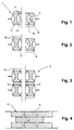
- Fig. 1 shows a section 1 of a sorption unit 2 of a device for air conditioning and Heat technology according to Fig. 9, with sheets for heat emission, on which water vapor is passed by.
- the sheets are double sheets with sheet metal walls 3 and 3 ', which are connected to one another at their ends (e.g. welded) are.
- strand-like zeolite profile body 4 arranged in the hollow chambers formed by the sheets 3 and 3 ' strand-like zeolite profile body 4 arranged. These have a double T shape on, with the top and bottom sides of the double-T in surface contact with the Sheets 3 and 3 'stand.
- the upper sides or Bottom sides of the X-body are designed to be as large as possible To form contact surface.
- the adjacent X-bodies or double T-bodies form in the area their constrictions 5 each from channels 6 through which the steam flow can.
- the adjacent X-bodies or double T-bodies form in the area their constrictions 5 each from channels 6 through which the steam flow can.
- A is preferably used in the sorption unit or in the entire air conditioning unit Maintain pressure below atmospheric pressure. With that presses the external pressure of the relatively thin sheets 3 and 3 'against each other, and the zeolite bodies are pressed against the sheets 3 and 3 'and in their position held.
- the device components sorption unit 2, buffer device 8 and condenser / evaporator unit 7 are designed as a laminated core, with each Sheets 9a, 9b, 9c, etc. are parallel to each other, which are stamped on both sides 10 and impressions 11, 14 are provided.
- These versions 10 and Imprints 11, 14 are arranged such that they have a combined effect as a "flow labyrinth", as a "water collecting basin” and as a mechanical "spacer” of the sheets 9a, 9b, etc. unfold.
- the impressions serve as collecting trays of condensing water vapor in the regeneration phase of the sorption device.
- impressions 11 are therefore also down in the buffer zone 8 curved to stop the water droplets and drain them down, while curved upward in the condenser / evaporator unit 7, to serve as drip trays so that the condensed water is even is distributed in the condenser / evaporator unit and not only in the accumulates lower area.
- the forms 10 can each over half of the sorption unit 2 or the condenser / evaporator unit 7 are preferably mutually arranged and complement each other Characteristics 10 of a second sorption unit or condenser / evaporator unit, on the first sorption unit or condenser / evaporator unit is hung up to form a package.
- These characteristics 10 serve in their mutual addition as a continuous spacer across the entire Width of the units and thus form an additional part of an air conditioner Flow channels for the passage of a room air flow, which in the Area of the evaporator 7 heat is withdrawn, or in the area of the sorption unit 2 for absorbing heat from the exothermic process.
- On the other hand serves the air flow in the regeneration phase of the air conditioner in the area the sorption unit 2 for delivering heat to the zeolite and for cooling in the condensation of the water in the condenser / evaporator unit 7.
- the impressions 11 touch extend into the evaporator 7 from both sides and serve on this way as a support of the two sheets against each other.
- impressions 11 are straight in the lower area and in the area of their edges curved in an arc, and their distance from the sorption unit increases 2 towards the water separation effect due to the increasing To increase steam flow to the sorption unit 2.
- the impressions 11 serving as spacers can be in the upper region of the evaporator 7 have a somewhat greater curvature, so that the collected Amount of water there is greater than in the lower region of the evaporator 7, where the water condensate normally collects. That way advantageously achieved that the most uniform possible distribution during the cooking process of the evaporating water over the entire evaporator cross section of the Condenser / evaporator unit 7 takes place.
- On their underside they can be fin-like Have guide fins that ensure that the water even at a Inclination of the air conditioner (if it is located in a caravan, for example, on the driving on a downhill road or decelerating or accelerating exposed) is derived downwards.
- the top of the sheets can be mechanically and / or chemically roughened.
- FIG. 9 illustrates how, from a sorption unit 2 according to the invention, one inventive condenser / evaporator unit 7 and an inventive Buffer section 8 a "layered" and compact, made up of individual Storage elements existing air conditioner can be formed.
- the individual storage elements are placed one on top of the other, with the surfaces held at a distance by the spacers 10 serving as characteristics become.
- the transverse channels formed by the spacers are used for the passage of air (see arrow 13 in Fig. 9).
- the channels have an i.w. constant Cross-section so that a uniform air flow is generated and the air in the evaporator area can be cooled evenly.
- the condenser area of the sorption unit 2 heat generated by the air flow well dissipated.
- the condenser / evaporator unit 7 and sorption unit 2 can, as in the 9, can be directly connected by the buffer section 8. It is but also conceivable that the condenser / evaporator unit 7 and sorption unit 2 are connected via a longer pipeline, this pipeline itself can be designed as a capacitor by on its outside Appropriate cooling fins are arranged so that in the expulsion phase, in which the water contained in the zeolite is expelled by the application of heat and the sorption unit 2 is regenerated, generated water vapor in the area the pipeline is condensed and as water in the evaporator 7 got back.
- a valve could also be arranged in this pipeline, with which the connection between the evaporator 7 and the sorption unit 2 is temporarily closed and only opened when cooling capacity is requested.
- FIGS. 10 to 14 Alternative embodiments for the condenser / evaporator unit according to the invention result from FIGS. 10 to 14.
- the hollow body of the condenser / evaporator unit consists of two z. B. by roll welding interconnected sheet metal half-shells 15, 16, between which an insert 17 is taken from a highly hygroscopic material. Because this deposit is made Glass fiber or felt material is used to avoid dissolving the Provided a support structure 18 due to mechanical stress, which is formed by a screen plate.
- the sheet metal shell has on the top 15 rib-like forms 19, which serve as spacers for another Condenser / evaporator unit serve.
- the condenser / evaporator unit shown in FIG. 11 is similar to the previous embodiment, but are on both sides of the Insert 17 sieve plates 18 are provided, the sieve plates each only over extend the undulating area of the respective sheet metal half-shell, since the opposite side of the insert covered by the sheet metal half shell itself becomes.
- the spacers 19 are shortened in their longitudinal extent, however alternately on the surface of the respective sheet metal half shell 15 ' or 16 'arranged. Form the undulating areas of the sheet metal half-shells longitudinally extending channels through which the water vapor flows.
- two inserts 17 are provided, which are kept at a distance by means of a spacer 20.
- the spacer 20 can also consist of a screen plate, which essentially is bent in a meandering shape.
- the sheet can also be bent in a zigzag shape 13, as shown in the embodiment of FIG. 13, wherein In the web area and in the respective contact surfaces, indentations or stampings 21, 22 are provided. These impressions or features serve to stabilize the relatively thin-walled sheet. It is advantageous if the values are not in the Area of the contact surfaces of the inserts are arranged, as can be avoided should be that the deposits on these steep. Rather extend the expressions then fit into the space between the deposits or - in the contact area to the direction facing away from the insert.
Landscapes
- Engineering & Computer Science (AREA)
- Mechanical Engineering (AREA)
- General Engineering & Computer Science (AREA)
- Physics & Mathematics (AREA)
- Thermal Sciences (AREA)
- Life Sciences & Earth Sciences (AREA)
- Sustainable Development (AREA)
- Chemical & Material Sciences (AREA)
- Combustion & Propulsion (AREA)
- Sorption Type Refrigeration Machines (AREA)
- Drying Of Gases (AREA)
Applications Claiming Priority (2)
| Application Number | Priority Date | Filing Date | Title |
|---|---|---|---|
| DE19730136A DE19730136A1 (de) | 1997-07-14 | 1997-07-14 | Gerät der Klimatechnik sowie dessen Komponenten |
| DE19730136 | 1997-07-14 |
Publications (3)
| Publication Number | Publication Date |
|---|---|
| EP0892225A2 true EP0892225A2 (fr) | 1999-01-20 |
| EP0892225A3 EP0892225A3 (fr) | 2001-04-18 |
| EP0892225B1 EP0892225B1 (fr) | 2004-12-15 |
Family
ID=7835666
Family Applications (1)
| Application Number | Title | Priority Date | Filing Date |
|---|---|---|---|
| EP98112577A Expired - Lifetime EP0892225B1 (fr) | 1997-07-14 | 1998-07-07 | Appareil de conditionnement d'air et ses composants |
Country Status (5)
| Country | Link |
|---|---|
| US (1) | US6213197B1 (fr) |
| EP (1) | EP0892225B1 (fr) |
| JP (1) | JPH11108500A (fr) |
| AU (1) | AU741612B2 (fr) |
| DE (2) | DE19730136A1 (fr) |
Cited By (23)
| Publication number | Priority date | Publication date | Assignee | Title |
|---|---|---|---|---|
| EP1150077A1 (fr) | 2000-04-27 | 2001-10-31 | ZEO-TECH Zeo-Tech GmbH | Conteneur à sorption avec une enveloppe flexible |
| WO2003087682A1 (fr) * | 2002-04-18 | 2003-10-23 | Sortech Ag | Pompe a chaleur a sorption solide |
| US11571945B2 (en) | 2018-12-21 | 2023-02-07 | Dometic Sweden Ab | Roof top air conditioner unit, methods for producing, assembling and installing the roof top air conditioner unit and vehicle with the roof top air conditioner unit |
| US11752827B2 (en) | 2019-08-28 | 2023-09-12 | Dometic Sweden Ab | Air conditioner |
| USD1010080S1 (en) | 2020-05-15 | 2024-01-02 | Dometic Sweden Ab | Housing for air conditioning apparatus |
| US11933285B2 (en) | 2018-04-23 | 2024-03-19 | Dometic Sweden Ab | Damped mobile compressor |
| US11951798B2 (en) | 2019-03-18 | 2024-04-09 | Dometic Sweden Ab | Mobile air conditioner |
| USD1027143S1 (en) | 2021-07-12 | 2024-05-14 | Dometic Sweden Ab | Housing shroud for an air conditioner |
| US11987093B2 (en) | 2019-03-18 | 2024-05-21 | Dometic Sweden Ab | Mobile air conditioner |
| USD1057118S1 (en) | 2021-08-16 | 2025-01-07 | Dometic Sweden Ab | Housing for a heat exchanger |
| US12233682B2 (en) | 2018-06-18 | 2025-02-25 | Dometic Sweden Ab | Heating, ventilation and air conditioning system with illumination |
| US12263717B2 (en) | 2020-07-09 | 2025-04-01 | Dometic Sweden Ab | Air outlet, heater or air conditioning unit with such an air outlet, recreational vehicle with an air outlet, heater and/or air conditioning unit and methods for attaching, operating and converting an air outlet |
| US12264874B2 (en) | 2018-06-18 | 2025-04-01 | Dometic Sweden Ab | Heating, ventilation and air conditioning system with illumination |
| USD1073892S1 (en) | 2021-01-26 | 2025-05-06 | Dometic Sweden Ab | Air conditioning housing |
| US12291078B2 (en) | 2020-05-15 | 2025-05-06 | Dometic Sweden Ab | Air conditioning unit |
| US12358343B2 (en) | 2019-08-28 | 2025-07-15 | Dometic Sweden Ab | Climatization and window system for mobile homes |
| US12377704B2 (en) | 2019-08-28 | 2025-08-05 | Dometic Sweden Ab | Component of climatization system or window system |
| US12377705B2 (en) | 2020-05-15 | 2025-08-05 | Dometic Sweden Ab | Air conditioning unit |
| US12539734B2 (en) | 2019-01-23 | 2026-02-03 | Dometic Sweden Ab | Combination of roof top air conditioning unit base pan and air inlet duct |
| US12545076B2 (en) | 2022-01-20 | 2026-02-10 | Dometic Sweden Ab | Roof-mounted unit for air conditioner of vehicle, and air conditioner comprising same |
| US12558936B2 (en) | 2021-01-20 | 2026-02-24 | Dometic Sweden Ab | Heating arrangement and heat distribution unit for such a heating arrangement |
| US12565081B2 (en) | 2021-01-26 | 2026-03-03 | Dometic Sweden Ab | Air conditioning system for a vehicle |
| US12589627B2 (en) | 2019-08-28 | 2026-03-31 | Dometic Sweden Ab | Structure for moving wire from exterior to interior of a vehicle |
Families Citing this family (11)
| Publication number | Priority date | Publication date | Assignee | Title |
|---|---|---|---|---|
| GB0217332D0 (en) * | 2002-07-25 | 2002-09-04 | Univ Warwick | Thermal compressive device |
| JP4752618B2 (ja) * | 2006-05-30 | 2011-08-17 | パナソニック株式会社 | 蓄熱システム |
| GB0617721D0 (en) * | 2006-09-08 | 2006-10-18 | Univ Warwick | Heat exchanger |
| DE102007056473A1 (de) * | 2007-11-22 | 2009-05-28 | Behr Gmbh & Co. Kg | Vorrichtung und Verfahren zur Klimatisierung eines Kraftfahrzeugs |
| DE102010004344A1 (de) | 2010-01-11 | 2011-07-14 | Viessmann Werke GmbH & Co KG, 35108 | Beschichtungsverfahren und Adsorberelement |
| JP2012211713A (ja) * | 2011-03-30 | 2012-11-01 | Toyota Central R&D Labs Inc | 化学蓄熱反応器及び化学蓄熱システム |
| JP6221784B2 (ja) * | 2014-01-30 | 2017-11-01 | 株式会社デンソー | 化学蓄熱システム |
| DK178553B1 (en) | 2014-04-25 | 2016-06-13 | Teknologisk Inst | Temperature fluctuation and temperature gradient resistant coating composition having also corrosion inhibiting properties, method for making the coating and use thereof |
| USD917036S1 (en) | 2018-02-20 | 2021-04-20 | Dometic Sweden Ab | Air distribution box |
| CN110385958B (zh) | 2018-04-16 | 2024-06-18 | 多美达瑞典有限公司 | 空气分配设备 |
| CN113771782B (zh) * | 2021-10-15 | 2024-02-06 | 武汉萨普科技股份有限公司 | 一种房车操控系统 |
Citations (1)
| Publication number | Priority date | Publication date | Assignee | Title |
|---|---|---|---|---|
| DE4233062A1 (de) | 1992-10-01 | 1994-04-07 | Electrolux Leisure Appliances | Sorptionsapparat zur Verwendung in einer Kühlanlage |
Family Cites Families (22)
| Publication number | Priority date | Publication date | Assignee | Title |
|---|---|---|---|---|
| GB286269A (en) * | 1927-03-02 | 1928-12-20 | Metallurg De Hoboken Soc Gen | Improvements in and relating to filling bodies for reaction towers |
| BE758315A (fr) * | 1969-11-04 | 1971-04-30 | Thermo Bauelement A G | Accumulateur de chaleur pour appareils alimentes en courant de nuit |
| US4637218A (en) * | 1974-11-04 | 1987-01-20 | Tchernev Dimiter I | Heat pump energized by low-grade heat source |
| JPS5596892A (en) * | 1979-01-18 | 1980-07-23 | Hisaka Works Ltd | Heat transfer plate for plate type evaporator |
| DE3016290A1 (de) * | 1979-04-30 | 1980-11-20 | Hans Ivar Wallsten | Stabile formlinge aus sorbens und verfahren zu ihrer herstellung |
| US4477396A (en) * | 1980-08-13 | 1984-10-16 | Battelle Development Corp. | Countercurrent flow absorber and desorber |
| US4461733A (en) * | 1983-03-28 | 1984-07-24 | Arvin Industries, Inc. | Capillary fin media |
| US4544513A (en) * | 1983-04-15 | 1985-10-01 | Arvin Industries, Inc. | Combination direct and indirect evaporative media |
| JPS60103297A (ja) * | 1983-11-09 | 1985-06-07 | Hitachi Zosen Corp | シエルアンドチユ−ブ形蓄熱槽熱交換器 |
| DE3342985A1 (de) * | 1983-11-28 | 1985-06-13 | Fritz Dipl.-Ing. Kaubek | Kontinuierlichwirkende sorptionsapparate und verfahren zu deren betrieb |
| EP0464874B1 (fr) * | 1987-11-17 | 1996-02-28 | Shinwa Sangyo Co., Ltd. | Echangeur de chaleur pour tour de réfrigération |
| DE3901558A1 (de) * | 1989-01-20 | 1990-07-26 | Zeolith Tech | Sorptionsbehaelter fuer feste sorptionsmittel |
| JPH0391660A (ja) * | 1989-09-04 | 1991-04-17 | Nishiyodo Kuuchiyouki Kk | 吸着式蓄熱装置及び該装置を利用した吸着式蓄熱システム |
| EP0518833B1 (fr) * | 1991-06-13 | 1998-05-13 | Enea Ente Per Le Nuove Tecnologie, L'energia E L'ambiente | Pompe à chaleur pour le chauffage ou le refroidissement de bâtiments et, en combinaison, pour la fourniture de l'eau chaude pour des installations sanitaires |
| FR2698098B1 (fr) * | 1992-11-13 | 1994-12-16 | Ceca Sa | Blocs adsorbants pour pompes à chaleur chimiques et leur procédé d'obtention. |
| DE19507769A1 (de) * | 1994-09-12 | 1996-03-14 | Electrolux Leisure Appliances | Sorptions-Kühlaggregat |
| MX9701840A (es) * | 1994-09-12 | 1997-06-28 | Electrolux Leisure Appliances | Unidad de refrigeracion de absorcion. |
| DE4438084A1 (de) * | 1994-10-25 | 1996-05-02 | Franz Hegele | Sorptionsaggregat |
| AUPN123495A0 (en) * | 1995-02-20 | 1995-03-16 | F F Seeley Nominees Pty Ltd | Contra flow heat exchanger |
| US5558748A (en) * | 1995-05-12 | 1996-09-24 | Basf Corporation | Plate-type distillation/condensation apparatus and method of use |
| DE19539102A1 (de) * | 1995-10-20 | 1997-04-24 | Webasto Thermosysteme Gmbh | Sorptionsmodul und Verfahren zum Betreiben eines solchen |
| US5944094A (en) * | 1996-08-30 | 1999-08-31 | The Marley Cooling Tower Company | Dry-air-surface heat exchanger |
-
1997
- 1997-07-14 DE DE19730136A patent/DE19730136A1/de not_active Withdrawn
-
1998
- 1998-07-07 EP EP98112577A patent/EP0892225B1/fr not_active Expired - Lifetime
- 1998-07-07 DE DE59812376T patent/DE59812376D1/de not_active Expired - Fee Related
- 1998-07-10 US US09/113,416 patent/US6213197B1/en not_active Expired - Fee Related
- 1998-07-13 JP JP10197631A patent/JPH11108500A/ja active Pending
- 1998-07-14 AU AU76158/98A patent/AU741612B2/en not_active Ceased
Patent Citations (1)
| Publication number | Priority date | Publication date | Assignee | Title |
|---|---|---|---|---|
| DE4233062A1 (de) | 1992-10-01 | 1994-04-07 | Electrolux Leisure Appliances | Sorptionsapparat zur Verwendung in einer Kühlanlage |
Cited By (33)
| Publication number | Priority date | Publication date | Assignee | Title |
|---|---|---|---|---|
| EP1150077A1 (fr) | 2000-04-27 | 2001-10-31 | ZEO-TECH Zeo-Tech GmbH | Conteneur à sorption avec une enveloppe flexible |
| WO2003087682A1 (fr) * | 2002-04-18 | 2003-10-23 | Sortech Ag | Pompe a chaleur a sorption solide |
| CN1304800C (zh) * | 2002-04-18 | 2007-03-14 | 索尔泰克股份公司 | 固体吸附式热泵 |
| US7251955B2 (en) | 2002-04-18 | 2007-08-07 | Sortech, Ag | Solid sorption heat pump |
| US12497958B2 (en) | 2018-04-23 | 2025-12-16 | Dometic Sweden Ab | Damped mobile compressor |
| US11933285B2 (en) | 2018-04-23 | 2024-03-19 | Dometic Sweden Ab | Damped mobile compressor |
| US12264874B2 (en) | 2018-06-18 | 2025-04-01 | Dometic Sweden Ab | Heating, ventilation and air conditioning system with illumination |
| US12233682B2 (en) | 2018-06-18 | 2025-02-25 | Dometic Sweden Ab | Heating, ventilation and air conditioning system with illumination |
| US11571945B2 (en) | 2018-12-21 | 2023-02-07 | Dometic Sweden Ab | Roof top air conditioner unit, methods for producing, assembling and installing the roof top air conditioner unit and vehicle with the roof top air conditioner unit |
| US12090811B2 (en) | 2018-12-21 | 2024-09-17 | Domestic Sweden Ab | Roof top air conditioner unit, methods for producing, assembling and installing the roof top air conditioner unit and vehicle with the roof top air conditioner unit |
| US12539734B2 (en) | 2019-01-23 | 2026-02-03 | Dometic Sweden Ab | Combination of roof top air conditioning unit base pan and air inlet duct |
| US11987093B2 (en) | 2019-03-18 | 2024-05-21 | Dometic Sweden Ab | Mobile air conditioner |
| US11951798B2 (en) | 2019-03-18 | 2024-04-09 | Dometic Sweden Ab | Mobile air conditioner |
| US12427828B2 (en) | 2019-03-18 | 2025-09-30 | Dometic Sweden Ab | Mobile air conditioner |
| US12589627B2 (en) | 2019-08-28 | 2026-03-31 | Dometic Sweden Ab | Structure for moving wire from exterior to interior of a vehicle |
| US11752827B2 (en) | 2019-08-28 | 2023-09-12 | Dometic Sweden Ab | Air conditioner |
| US12377704B2 (en) | 2019-08-28 | 2025-08-05 | Dometic Sweden Ab | Component of climatization system or window system |
| US12358343B2 (en) | 2019-08-28 | 2025-07-15 | Dometic Sweden Ab | Climatization and window system for mobile homes |
| US12377705B2 (en) | 2020-05-15 | 2025-08-05 | Dometic Sweden Ab | Air conditioning unit |
| USD1114953S1 (en) | 2020-05-15 | 2026-02-24 | Dometic Sweden Ab | Housing for air conditioning apparatus |
| US12291078B2 (en) | 2020-05-15 | 2025-05-06 | Dometic Sweden Ab | Air conditioning unit |
| USD1010080S1 (en) | 2020-05-15 | 2024-01-02 | Dometic Sweden Ab | Housing for air conditioning apparatus |
| USD1053326S1 (en) | 2020-05-15 | 2024-12-03 | Dometic Sweden Ab | Air conditioning housing |
| USD1053327S1 (en) | 2020-05-15 | 2024-12-03 | Dometic Sweden Ab | Housing portion for air conditioning apparatus |
| US12263717B2 (en) | 2020-07-09 | 2025-04-01 | Dometic Sweden Ab | Air outlet, heater or air conditioning unit with such an air outlet, recreational vehicle with an air outlet, heater and/or air conditioning unit and methods for attaching, operating and converting an air outlet |
| US12558936B2 (en) | 2021-01-20 | 2026-02-24 | Dometic Sweden Ab | Heating arrangement and heat distribution unit for such a heating arrangement |
| USD1073892S1 (en) | 2021-01-26 | 2025-05-06 | Dometic Sweden Ab | Air conditioning housing |
| US12565081B2 (en) | 2021-01-26 | 2026-03-03 | Dometic Sweden Ab | Air conditioning system for a vehicle |
| USD1067400S1 (en) | 2021-07-12 | 2025-03-18 | Dometic Sweden Ab | Housing for an air conditioner |
| USD1027143S1 (en) | 2021-07-12 | 2024-05-14 | Dometic Sweden Ab | Housing shroud for an air conditioner |
| USD1066626S1 (en) | 2021-07-12 | 2025-03-11 | Dometic Sweden Ab | Housing shroud for an air conditioner |
| USD1057118S1 (en) | 2021-08-16 | 2025-01-07 | Dometic Sweden Ab | Housing for a heat exchanger |
| US12545076B2 (en) | 2022-01-20 | 2026-02-10 | Dometic Sweden Ab | Roof-mounted unit for air conditioner of vehicle, and air conditioner comprising same |
Also Published As
| Publication number | Publication date |
|---|---|
| EP0892225A3 (fr) | 2001-04-18 |
| AU7615898A (en) | 1999-01-21 |
| JPH11108500A (ja) | 1999-04-23 |
| US6213197B1 (en) | 2001-04-10 |
| DE19730136A1 (de) | 1999-01-21 |
| EP0892225B1 (fr) | 2004-12-15 |
| DE59812376D1 (de) | 2005-01-20 |
| AU741612B2 (en) | 2001-12-06 |
Similar Documents
| Publication | Publication Date | Title |
|---|---|---|
| EP0892225B1 (fr) | Appareil de conditionnement d'air et ses composants | |
| EP0131270B1 (fr) | Absorbeur utilisant une matière solide pour un cycle d'absorption | |
| DE3122197C2 (de) | Kondensator | |
| DE69102755T2 (de) | Plattenverdampfer. | |
| DE2801076C3 (de) | Wärmeaustauscher bestehend aus Schichten von paarweise einander zugeordneten Wänden | |
| EP1992898B1 (fr) | Echangeur thermique pour fluides caloporteurs gazeux | |
| EP1918668A1 (fr) | Dispositif destiné à la réception d'un fluide à l'aide de forces capillaires et procédé destiné à la fabrication du dispositif | |
| DE3507981A1 (de) | Waermetauscher mit getrennt angeordneten verdampfungs-und kondensationszonen | |
| DE10220532A1 (de) | Wärmetauscher | |
| DE102020007211A1 (de) | Adsorptionskältevorrichtung und Verfahren zum Erzeugen von Adsorptionskälte aus Wärme | |
| DE19654261A1 (de) | Kühlaggregat | |
| EP0901601B1 (fr) | Echangeur de chaleur | |
| DE9319430U1 (de) | Wärmetauscherblock | |
| EP3027981B1 (fr) | Module d'adsorption | |
| DE4009997A1 (de) | Verdampfer | |
| EP2310756B1 (fr) | Élément intégrable à intégrer dans un dispositif d'humidification, de nettoyage et/ou de refroidissement d'un fluide, en particulier d'un gaz comme l'air par exemple, et procédé de fabrication d'un corps intégrable avec un tel élément intégrable | |
| DE102021202296A1 (de) | Wärmeübertragungsmodul für Entfeuchter und Verfahren zur Herstellung desselben | |
| DE69605347T2 (de) | Wärmetauscher mit gelöteten Platten | |
| EP3433544B1 (fr) | Module à insérer dans un dispositif d'humidification, de purification et/ou de refroidissement d'un fluide, en particulier d'un gaz comme l'air par exemple | |
| DE10141525A1 (de) | Stoff- und Wärmeaustauschreaktor | |
| EP2015006A2 (fr) | Pompe à chaleur | |
| DE69210039T2 (de) | Verbrennungsvorrichtung | |
| DE102019134587B4 (de) | Wärmeübertrager und Adsorptionsmaschine | |
| EP2853852B1 (fr) | Elément d'intégration pour un dispositif de traitement d'un fluide utile au moyen d'un fluide de travail | |
| DE102007044976A1 (de) | Vorrichtung zur Aufnahme eines Fluids mittels Kapillarkräften und Verfahren zur Herstellung der Vorrichtung |
Legal Events
| Date | Code | Title | Description |
|---|---|---|---|
| PUAI | Public reference made under article 153(3) epc to a published international application that has entered the european phase |
Free format text: ORIGINAL CODE: 0009012 |
|
| AK | Designated contracting states |
Kind code of ref document: A2 Designated state(s): DE FR GB IT NL |
|
| AX | Request for extension of the european patent |
Free format text: AL;LT;LV;MK;RO;SI |
|
| PUAL | Search report despatched |
Free format text: ORIGINAL CODE: 0009013 |
|
| AK | Designated contracting states |
Kind code of ref document: A3 Designated state(s): AT BE CH CY DE DK ES FI FR GB GR IE IT LI LU MC NL PT SE |
|
| AX | Request for extension of the european patent |
Free format text: AL;LT;LV;MK;RO;SI |
|
| 17P | Request for examination filed |
Effective date: 20010911 |
|
| AKX | Designation fees paid |
Free format text: DE FR GB IT NL |
|
| RAP1 | Party data changed (applicant data changed or rights of an application transferred) |
Owner name: DOMETIC AG |
|
| 17Q | First examination report despatched |
Effective date: 20031107 |
|
| GRAP | Despatch of communication of intention to grant a patent |
Free format text: ORIGINAL CODE: EPIDOSNIGR1 |
|
| GRAS | Grant fee paid |
Free format text: ORIGINAL CODE: EPIDOSNIGR3 |
|
| GRAA | (expected) grant |
Free format text: ORIGINAL CODE: 0009210 |
|
| AK | Designated contracting states |
Kind code of ref document: B1 Designated state(s): DE FR GB IT NL |
|
| REG | Reference to a national code |
Ref country code: GB Ref legal event code: FG4D Free format text: NOT ENGLISH |
|
| REF | Corresponds to: |
Ref document number: 59812376 Country of ref document: DE Date of ref document: 20050120 Kind code of ref document: P Owner name: BELOIT IRON WORKS |
|
| GBT | Gb: translation of ep patent filed (gb section 77(6)(a)/1977) |
Effective date: 20050321 |
|
| PLBE | No opposition filed within time limit |
Free format text: ORIGINAL CODE: 0009261 |
|
| STAA | Information on the status of an ep patent application or granted ep patent |
Free format text: STATUS: NO OPPOSITION FILED WITHIN TIME LIMIT |
|
| ET | Fr: translation filed | ||
| 26N | No opposition filed |
Effective date: 20050916 |
|
| PGFP | Annual fee paid to national office [announced via postgrant information from national office to epo] |
Ref country code: NL Payment date: 20060718 Year of fee payment: 9 |
|
| PGFP | Annual fee paid to national office [announced via postgrant information from national office to epo] |
Ref country code: FR Payment date: 20060719 Year of fee payment: 9 |
|
| PGFP | Annual fee paid to national office [announced via postgrant information from national office to epo] |
Ref country code: GB Payment date: 20060721 Year of fee payment: 9 |
|
| PGFP | Annual fee paid to national office [announced via postgrant information from national office to epo] |
Ref country code: IT Payment date: 20060731 Year of fee payment: 9 |
|
| PGFP | Annual fee paid to national office [announced via postgrant information from national office to epo] |
Ref country code: DE Payment date: 20060928 Year of fee payment: 9 |
|
| GBPC | Gb: european patent ceased through non-payment of renewal fee |
Effective date: 20070707 |
|
| NLV4 | Nl: lapsed or anulled due to non-payment of the annual fee |
Effective date: 20080201 |
|
| PG25 | Lapsed in a contracting state [announced via postgrant information from national office to epo] |
Ref country code: NL Free format text: LAPSE BECAUSE OF NON-PAYMENT OF DUE FEES Effective date: 20080201 Ref country code: DE Free format text: LAPSE BECAUSE OF NON-PAYMENT OF DUE FEES Effective date: 20080201 |
|
| PG25 | Lapsed in a contracting state [announced via postgrant information from national office to epo] |
Ref country code: GB Free format text: LAPSE BECAUSE OF NON-PAYMENT OF DUE FEES Effective date: 20070707 |
|
| REG | Reference to a national code |
Ref country code: FR Ref legal event code: ST Effective date: 20080331 |
|
| PG25 | Lapsed in a contracting state [announced via postgrant information from national office to epo] |
Ref country code: FR Free format text: LAPSE BECAUSE OF NON-PAYMENT OF DUE FEES Effective date: 20070731 |
|
| PG25 | Lapsed in a contracting state [announced via postgrant information from national office to epo] |
Ref country code: IT Free format text: LAPSE BECAUSE OF NON-PAYMENT OF DUE FEES Effective date: 20070707 |