The present invention relates to a refrigerator including a cooling compartment, a
heat pump, means for driving cool air, produced by the heat pump, through an
aperture into the cooling compartment, and flow directing means associated with the
aperture for directing said cool air and which includes a vertical blade pivotable about
a vertical axis.
Generally, a refrigerator has a cabinet in which there are a freezing compartment and
a fresh food compartment. These compartments are separated by a partition wall.
Doors are provided at the front of the freezing and cooling compartments. A cooling
system supplies the freezing compartment and the fresh food compartment with cool
air and comprises a compressor, a condenser and an evaporator. The cool air
generated by the evaporator flows along a supply duct formed at the back of each
compartment, and is then supplied into each cooling compartment through cool air
discharge ports opening thereinto by a fan.
In such a conventional refrigerator, however, cool air tends to be supplied into a
particular area of the cooling compartment and other areas tend to be less well served.
Consequently, a uniform temperature is not maintained throughout the cooling
compartment.
This problem has been addressed by providing cool air discharge ports in the side
walls of the cooling compartment as well as in its rear wall. However, there may be
still a dead-zone at an edge area which is not supplied with the cool air sufficiently.
Furthermore, the ducting required to supply cool air from the sides of the cooling
compartment reduces the space available for food and increases the cost of
manufacture.
The problem of adequately distributing cool air in a refrigerator is worse for larger
refrigerators.
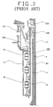
Figures 1 through 3 are a side view, a partial enlarged sectional view, and an exploded
perspective view of the main elements of a refrigerator having a device for dispersing
cool air as disclosed in WO-A-95/27278.
Referring to Figures 1 to 3, a refrigerator comprises freezing and fresh food
compartments 2, 3 in a cabinet 1, which are separated from each other by a partition
wall 5. Respective doors 6, 7 are provided for closing the compartments 2, 3. A
cooling system, comprising a compressor 11, a condenser (not shown), a freezing
compartment evaporator 12a, and a fresh food compartment evaporator 12b, is
installed in the cabinet 1. Cool air generated by the evaporators 12a, 12b is supplied
to the corresponding compartments 2, 3 by a freezing compartment fan 13a and a
fresh food compartment fan 13b respectively.
A partially cylindrical duct plate 9 is attached to an inner wall plate 23 forming the
rear inner wall surface of the fresh food compartment 3. The duct plate 9 has cool air
discharge ports 16, opening into the fresh food compartment 3, formed in it. A
supply duct 15 and a return duct 17, separated from each other by a seal plate 25, are
provided between the duct plate 9 and the rear wall 4 of the cabinet 1. A duct
member 21, for guiding downwards cool air blown by the fresh food compartment
fan 13b, is installed in the supply duct 15. Cool air generated by the fresh food
compartment evaporator 12b is blown by the fresh food compartment fan 13b and
then supplied to the fresh food compartment 3 via the supply duct 15 and the cool air
discharge ports 16.
A cool air dispersing device 130 is installed in the supply duct 15. The cool air
dispersing device 130 comprises a rotational shaft 131 having a vertical axis, cool air
dispersing blades 132 assembled with the rotational shaft 131 in correspondence with
respective cool air discharge ports 16, and a driving motor 135 for rotating the
rotational shaft 131. Each of the cool air dispersing blades 132 comprises three discs
136, 137, 138 disposed in parallel with each other along the shaft 131, and first and
second blade parts 133, 134 disposed between pairs of the discs 136, 137, 138. Each of
the blade parts 133, 134 is curved so that its cross-section is loosely S-shaped. The
blade parts 133, 134 are bent in opposite directions to each other.
In a refrigerator having the above-described constitution, when the driving motor 131
rotates the rotational shaft 131 at a low speed, cool air flowing along the supply duct
15 changes its direction along the curved surfaces of the cool air dispersing blades 132,
and is directed into the fresh food compartment 3 so as to disperse horizontally.
When concentrated cooling in a specific area is needed, the driving motor 135 stops
the rotational shaft 131 so that the cool air dispersing blades 132 direct cool air to the
specific area. However, since the blade parts 133, 134 of the cool air dispersing device
130 are S-shaped, the left or right sides of the fresh food compartment 3 may not be
supplied with the cool air sufficiently and the smooth flow of cool air may be
impeded by a vortices in the cool air formed about the cool air discharge ports 16.
Moreover, although such a conventional cool air dispersing device 130 can achieve
uniform distribution of cool air horizontally, the vertical distribution of cool air is
not sufficiently uniform. Consequently, there is a limitation in realizing uniform
cooling throughout the fresh food compartment 3.
A refrigerator according to the present invention is characterised in that the vertical
blade is configured for being reciprocally pivoted, for instance by drive means.
Preferably, the flow directing means comprises a plurality of vertical blades is
configured for being reciprocally pivoted.
A motor and a crank mechanism are preferably provided for driving the or each
vertical blade.
Preferably, the flow directing mean includes one or more substantially horizontal
blades pivotable about horizontal axes. In this case, there is preferably provided cam
mean mounted for rotation with the or both of the vertical blades, and cam follower
means for driving the or each horizontal blade when the or each vertical blade is
being driven. More preferably, the or each horizontal blade has a cutout
encompassing the area swept by one or both of the vertical blades. If there are two
parallel vertical blades, the or each horizontal blade preferably has two cutouts, each
encompassing the area swept by a vertical blade.
Embodiments of the present invention will now be described, by way of example,
with reference to Figures 4 to 24 of the accompanying drawings, in which:-
Hereinafter, exemplary embodiments of the present invention will be described in
detail with reference to the accompanying drawings. Parts that are the same as or
similar to parts shown in Figures 1 through 3 will be identified with the same
reference numerals. The description of the parts which are substantially the same as
those of the prior art will in general be omitted.
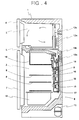
Referring to Figure 4, a refrigerator comprises a cabinet 1, a freezing compartment 2
and a fresh food compartment 3 formed within the cabinet 1 and separated by a
partition wall 5. The freezing compartment 2 is disposed above the fresh food
compartment 3. The compartments 2, 3 are provided with respective doors 6, 7.
Shelves 8 for supporting food and which divide the fresh food compartment 3 into
three areas, i.e. an upper area, a middle area, and a lower area, are installed in fresh
food compartment 3. A special fresh chamber 18 for storing food which requires a
specific temperature range is formed in the upper part of the fresh food compartment
3, and a vegetable chamber 19 for storing vegetables is formed at the bottom of the
fresh food compartment 3.
A cooling system, comprising a compressor 11, a condenser (not shown), a freezing
compartment evaporator 12a, and a fresh food compartment evaporator 12b, is
installed in the cabinet 1. The cool air generated by the evaporators 12a, 12b is
supplied into the corresponding cooling compartments 2, 3 by a freezing
compartment fan 13a and a fresh food compartment fan 13b respectively. A duct
plate 9 is attached on the inner wall plate 23, forming the rear wall of the fresh food
compartment 3. The duct plate 9 is partially cylindrical in shape so that it protrudes
in the form of an arc from the inner wall plate 23 into the fresh food compartment 3,
and has cool air discharge ports 16 opening into respective storing areas of the fresh
food compartment 3. Another cool air discharge port 16', opening into the special
fresh chamber 18 is provided in the upper area of the inner wall plate 23.
Between the duct plate 9 and the rear wall 4 of the cabinet 1, a supply duct 15 and a
return duct 17 are provided, which are partitioned from each other by a seal plate 25.
In the supply duct 15, a duct member 21 for guiding the cool air blown by the fresh
food compartment fan 13b downwardly is installed. The cool air generated by the
fresh food compartment evaporator 12b is blown by the fresh food compartment fan
13b so as to be supplied into the fresh food compartment 3 via the supply duct 15 and
the cool air discharge ports 16. A device for dispersing the cool air horizontally is
installed in the supply duct 15.
A supply duct 15 and a return duct 17 are provided between the duct plate 9 and the
rear wall 4 of the cabinet 1. These ducts 15, 17 are partitioned from each other
by a seal plate 25. A duct member 21 for guiding cool air, blown downwards by the
fresh food compartment fan 13b, is installed in the supply duct 15. The cool air
generated by the fresh food compartment evaporator 12b is blown by the fresh food
compartment fan 13b so as to be supplied into the fresh food compartment 3 via the
supply duct 15 and the cool air discharge ports 16. A device for dispersing the cool
air horizontally is installed in the supply duct 15.
Referring to Figure 5, the refrigerator has a device 30 for dispersing cool air
horizontally and a device 40 for dispersing the cool air vertically.
The horizontally dispersing device 30 has a vertical rotational shaft 31, three planar
dispersing horizontally dispersing blades 33, a pivoting member 80 for pivoting the
horizontally dispersing blades 33, and a driving motor 35 for rotating the pivoting
member 80.
The horizontally dispersing blades 33 are spaced along the shaft 31 so as to be near
respective cool air discharge ports 16. The upper end of the rotational shaft 31 is
supported by a supporting member (not shown). A journal part 32 is formed at the
bottom of the rotational shaft 31 and is inserted into a bearing hole 9g formed in the
lower part of the duct plate 9. It is preferable that the driving motor 35 is a stepping
motor whose stationary angular position can be controlled.
A pivot guide 37 is provided along the upper edge of the uppermost horizontally
dispersing blade 33. The pivot guide 37 has a guide groove 39 formed transverse to
the longitudinal direction of the rotational shaft 31.
The pivoting member 80 is coupled to the driving shaft 36 of the driving motor 35.
The pivoting member 80 has a pivot pin 81 which is eccentric with respect to the
rotational axis thereof. The pivot pin 81 is inserted into the guide groove 39.
When the driving motor 35 operates, the pivoting member 80 rotates causing the
pivot pin 81 to reciprocate in the guide groove 39. Consequently, the horizontally
dispersing blades 33 are rotated reciprocally about the rotational shaft 31. In this
situation, the angular range of the rotation of the horizontally dispersing blades 33
depends on the radial length of the pivot pin 81. As the horizontally dispersing
blades 33 reciprocate, the cool air discharged through the cool air discharge ports 16 is
dispersed horizontally.
The vertically dispersing device 40 comprises a plurality of vertically dispersing
blades 57 which are disposed near the cool air discharge ports 16 and which are
capable of pivoting about respective horizontal axes, a link member 61 installed in the
supply duct 15 so as to be capable of moving up and down, and a raising and lowering
cam 63 for raising and lowering the link member 61.
Each vertically dispersing blade 57 comprises a generally arcuate plate so as to
accommodate the horizontally dispersing blades 33 and horizontal stub shafts 53
extending from either end of the plate. The duct plate 9 has a pair of flanges 9e which
extend backward from the rear surface of both side margins of the duct plate 9. The
flanges 9e face each other and have a plurality of shaft holes 9f for receiving and
rotatably supporting the stub shafts 53 of the vertically dispersing blades 57. The
vertical dispersing blades 57 are capable of pivoting when their stub shafts 53 are
inserted into the shaft holes 9f.
The link member 61 is disposed parallel to the rotational shaft 31. The link member
61 is rod-shaped and has a plurality of partially ring-shaped hinge assembly parts 62
which protrude toward the vertically dispersing blades 57. Associated with a
respective hinge assembly part 62, each of the vertically dispersing blades 57 has a
horizontal, cylindrical hinge part 55 at the middle of its forward edge. The hinge
assembly parts 62 are engaged with the hinge parts 73 so that there can be relative
rotational movement therebetween.
A raising and lowering cam 63 is installed on the rotational shaft 31. The raising and
lowering cam 63 comprises a cylindrical cam body 66 and a cam groove 65 formed on
the outer surface of the cam body 66. The cam groove 65 is an inclined closed loop.
On the link member 61 is provided an operation part 67, protruding transversely of
the longitudinal direction of the link member 61, and the free end of the operation
part 67 is received by the cam groove 65.
The link member 61 also has a guiding piece 69 protruding towards the duct plate 9.
The guiding piece 69 is accommodated in a raising and lowering guiding part 49
formed on the inner wall of the duct plate 9. The raising and lowering guiding part
49 accommodates the guiding piece 69 so that the link member 61 moves up and
down without rotating.
The operation of the above-described refrigerator will now be described.
Referring to Figures 7 to 9, the horizontally dispersing blades 33 are rotated
reciprocally by the driving motor 35 and the pivoting member 80. When the
horizontally dispersing blades 33 are directed directly to the front during the rotation
of the rotational shaft 31 as shown in Figure 7, cool air in the supply duct 15 is
discharged to the front along both sides of the horizontally dispersing blades 33.
When the horizontally dispersing blades 33 are turned left or right as shown in
Figures 8 and 9, cool air is discharged to the left or the right.
As described, the discharging direction of the cool air changes as the angular position
of the horizontally dispersing blades 33 changes so that cool air is dispersed in the
fresh food compartment 3 uniformly. Moreover, since the horizontally dispersing
blades 33 are planar, vortices are not caused by the horizontally dispersing blades 33.
If a concentrated supply of cool air to a specific area such as the left side or the right
side is required, the driving motor 35 is stopped when the horizontally dispersing
blades 33 are directed to the specific area. In this situation, temperature sensors
placed at a plurality of positions in the fresh food compartment 3, as well as a control
part for controlling the driving motor 35 on the basis of the signals from the
temperature sensors have to be provided.
The horizontally dispersing blades 33 are disposed in association with respective the
cool air discharge ports 16. However, it is possible that only one long horizontally
dispersing blade be provided for directing cool air through all of the cool air discharge
ports 16.
While the horizontally dispersing device 30 operates, the raising and lowering cam 63
rotates with the shaft 31 and the link member 61 is raised and lowered by the
operation part 67 which is received in the cam groove 65. The raising and lowering
movement of the link member 61 causes pivoting of the vertically dispersing blades
57 by means of the hinge assembly part 62 and the hinge parts 55.
The raising and lowering motion of the link member 61 is guided vertically by the
guiding piece 69 and the raising and lowering guiding part 49. Consequently, the link
member 61 does not rotate but reciprocates in the vertical direction while the raising
and lowering cam 63 rotates.
Referring to Figure 10, while the vertically dispersing blades 71 are kept horizontal,
cool air is discharged horizontally. When the shaft 31 rotates clockwise by about 90
degrees, the vertically dispersing blades 57 are tilted upward as shown in Figure 11
and, in this situation, cool air is discharged upward to be supplied into the upper area
of the fresh food compartment 3. As the shaft 31 then rotates anti-clockwise by
about 90 degrees from the position shown in Figure 11, the vertically dispersing
blades 57 are returned to the horizontal state as shown in Figure 10, and as it further
rotates anti-clockwise by about 90 degrees, the vertically dispersing blades 57 are ilted
downwards as shown in Figure 12. In this situation, cool air is discharged
downward.
The repetition of this process ensures that cool air is evenly dispersed in the fresh
food compartment 3 both vertically and horizontally.
Referring to Figures 13 to 17, in a second embodiment, a horizontally dispersing
device 90 comprises a pair of parallel horizontally dispersing blades 93, which extend
past all of the cool air discharge ports 16. Each of the horizontally dispersing blades
93 has its own rotational shaft 91. The lower end of each rotational shaft 91 is
inserted into a bearing hole 29 formed at the bottom of the duct plate 9, and its upper
end thereof is supported by a supporting member which is not shown. Thus, the
horizontally dispersing blades 93 are supported on rotational shafts 91 for rotation
therewith.
Each of the rotational shafts 91 has a rod 94 at its upper end which extends in a
direction transverse to the axis of the respective rotational shaft 91, and a connecting
pin 95 protruding upward at the end of the rod 94. The rods 94 are connected to
each other by a connecting bar 96. More specifically, the connecting bar 96 has holes
97 at either ends and the connecting pins 95 are inserted into these holes 97. Thus,
the horizontally dispersing blades 93 are connected to each other while being kept
parallel with each other.
A driving motor 35 is installed above the connecting bar 96, and a cylindrical cam
member 99 is disposed between the driving motor 35 and the connecting bar 96.
The cam member 99 is coupled with the driving shaft 36 of the driving motor 35. A
substantially elliptical cam groove 99a is formed on the underside of the cam member
99. An operation pin 98, formed on the connecting bar 96, is received in the cam
groove 99a. Thus, when the cam member 99 is rotated by the driving motor 35, the
operation pin 98 is guided by the cam groove 99a, causing the connecting bar 96 to
reciprocate longitudinally.
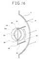
When the operation pin 98 is positioned where the cam groove 99a is narrow by the
rotation of the cam member 99, the connecting bar 96 is moved left as shown in
Figure 15 and the horizontally dispersing blades 93 are rotated to the right. When
the operation pin 98 is positioned where the cam groove 99a is wide by the continued
rotation of the cam member 99, the connecting bar 96 is moved right as shown in
Figure 16 and the horizontally dispersing blades 93 are rotated to the left. According
to such an operation, the horizontal dispersing blades 93 is rotated left and right
reciprocally about the axes of their rotational shafts 91 and cool air discharged
through the cool air discharge ports 16 is dispersed left and right. In such a situation,
the angular range of the reciprocal rotation depends on the range of the reciprocation
of the connecting bar 96.
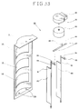
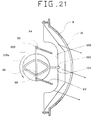
Referring to Figures 17 through 22, in a third embodiment, the construction of the
horizontally dispersing device 90 is substantially the same with that of the above-described
second embodiment but a vertically dispersing device 100 is provided. The
construction of the vertically dispersing device 100 is similar to that of the second
embodiment shown in Figures 13 through 16.
The vertically dispersing device 100 has vertically dispersing blades 107 having
horizontal rotational shafts 103 and hinge parts 102 respectively, and a link member
101 having hinge assembly parts 104 assembled with respective hinge parts 102.
The vertically dispersing blade 107 is formed with a cutout 108. The cutout 108
accommodates the swept area of the horizontally dispersing blades 93 so as to allow
the reciprocal rotation of the horizontally dispersing blades 93.
A cam member 109 is installed on the driving shaft 36 of the driving motor 35. As
shown in Figure 18, on the underside of the cam member 109 is formed a cam groove
109a into which the operation pin 98 of the connecting bar 96 is inserted. The cam
groove 109a is substantially elliptical.
A raising and lowering cam groove 109b is formed in the outer surface of the cam
member 109. The cam groove 109b is a closed loop. The upper end of the link
member 101 is inserted into the raising and lowering gam groove 109b so that
rotational movement of the cam member 109 is converted into vertical reciprocal
movement of the link member 101. As the link member 101 is moved up and down,
the vertically dispersing blades 107 are vertically reciprocally rotated. That is, as
shown in Figures 19 and 20, the vertically dispersing blades 107 are rotated upward
and downward by the rising and falling of the link member 101. Furthermore,
according to the rotation of the cam member 109, the horizontally dispersing blades
93 are rotated left or right as shown in Figures 21 and 22 so that cool air is dispersed
horizontally.
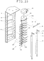
Referring to Figures 23 and 24, in a modified form, the construction of the
horizontally dispersing device 90 and the vertically dispersing device 100 is
substantially the same with that of the third embodiment except for the shape of the
vertically dispersing blades 107.
Each of the vertically dispersing blades 107 has a pair of cutouts 108a formed at the
rear left and rear right sides thereof. The cutouts 108a correspond to the pair of
horizontally dispersing blades 93. That is, each of the cut parts 108a accommodates
the swept area of one of the horizontally dispersing blades 93 so at to allow the
reciprocal rotation of the horizontally dispersing blades 93.
Each vertically dispersing blade 107 is formed with a hole 110 instead of the hinge
part 102 shown in the third embodiment, and the link member 101 is formed with
supporting protrusions 101a instead of the hinge assembly parts shown in the third
embodiment. The link member 101 passes through the vertically dispersing blades
107 through the holes 110, and the vertically dispersing blades 107 are supported by
the supporting protrusions 101a. When the link member 101 moves up, the
vertically dispersing blades 107 pivot upward, and when the link member 101 moves
down, the vertical dispersing blades 107 pivot downward. Accordingly, the cool air
is dispersed vertically by the vertically dispersing blades 107.
According to the above-described modification, the cutout areas of the vertical
dispersing blade 107 are smaller than that of the vertically dispersing blade of
the third embodiment. Therefore, the cool air is dispersed in vertical direction
more efficiently.
As described above, according to the present invention, a stable cool air flow and a
uniform distribution of the cool air can be achieved without vortices in the cool air
near the cool air discharge ports. Furthermore, the uniform distribution of the cool
air can be achieved not only horizontally but also in vertical direction when suitable
blades are provided. Since the horizontally dispersing blades are reciprocally rotated
in the angular range, the efficiency for dispersing cool air in the horizontal direction
is more enhanced.